# 🌡️ UE LU1SXPFL - L1 CMI Physique


# Description de l'UE

L'UE LU1SXPFL est une UE d'initiation aux principales techniques utilisées dans les fablabs (conception et fabrication numérique et prototypage électronique) proposée aux étudiants du CMI Physique au niveau L1. L'UE commence par un historique des fablabs, d'où ils viennent, ce qu'on y fait, etc. Suivent, quelques séances de formation aux outils de conception 2d/3d (Inkscape, OpenSCAD, FreeCAD), un introduction aux machines (découpeuse laser, imprimantes 3d) et une initiation au prototypage électronique utilisant des cartes de développement (Arduino Uno, M5Stack) et des modules (capteurs, afficheurs, LEDs, etc.). Le reste du temps est dédié à la réalisation d'un projet au fablab combinant conception - fabrication - prototypage.

**Enseignant responsable:** Vincent Dupuis

**Période et volume horaire:** janvier 2023-avril 2023, 30h par étudiant (10 séances de 3h)

**Effectifs:** L1 CMI Physique, ~ 30 étudiants

**Quelques liens:**

[fablabs.io](https://www.fablabs.io/) : carte interactive du réseau international des fablabs, beaucoup d'informations

[fabacademy](https://fabacademy.org/) : page de la formation de haut niveau dispensée au sein des fablabs du réseau de janvier à juin. Plus interessant, l'archive des [documentations de la fabacademy](https://fabacademy.org/archive/) qui rassemble les documentations des étudiants

quelques sites où l'on trouve un grand nombre de projets documentés : [hackster.io](https://www.hackster.io/),[instructables](https://www.instructables.com/), [hackaday.](https://hackaday.com/)

# New Page


# Groupe B1 - Sonomètre portatif

Membres du groupe : Maïlys HERMANN-BOYER, Shirel FELLOUS, Lily-Rose GAVANON

Page de documentation d'étudiantes en L1 de CMI Physique dans le cadre du Projet Fablab (découverte du Fablab SU &amp; réalisation d'un projet incluant un capteur environnemental) en 10 séances de 3h

---

### <span style="color: #c2e0f4;">**Découverte du Fablab**</span>

<details id="bkmrk-s%C3%A9ance-1-%3A-introduct"><summary>Séance 1 : Introduction à l'UE</summary>

Aujourd'hui, ce 23 janvier 2023, nous avons eu la chance de participer à notre premier cours de l'UE Fablab. Cela a été organisé dans l'enceinte du Laboratoire Fablab qui se trouve dans le bâtiment Esclangon de l'université de la Sorbonne. Le Fablab est un atelier créé à l'origine par le professeur **Neil Gershenfeld** au MIT, dans l'optique de réunir différentes personnes passionnées par la recherche et le développement de créations quelconques. Un réseau mondial de laboratoires s'est donc formé afin de donner accès à des outils de fabrication numérique à de multiples individus.

Nous avons donc pu visiter ce laboratoire et suivre les explications des différentes machines telles que des imprimantes 3D, des fraiseuses numériques ou encore des découpeuses laser.

Notre but dans les séances à venir sera de réfléchir à un projet permettant la création d'un objet utilisable au quotidien. Ce projet devra inclure un ou plusieurs capteurs environnementaux.

</details><details id="bkmrk-s%C3%A9ance-2-%3A-circuits-"><summary>Séance 2 : Circuits Arduino et capteurs</summary>

Ce lundi 30 janvier, la séance portait sur le **prototypage électronique**. Nous avons été initiés à l'histoire de l'électronique, du tube à vide en 1904 au M5Stack en 2017 ; nous avons pu voir la chronologie d'apparition des différentes techniques et découvertes électroniques.

Nous avons découvert **la carte Arduino**, prototypée en 2003 par un étudiant en Master et apparue réellement sous forme de carte en 2005. Ce composant est en fait un microcontrôleur, capable de capter des signaux analogiques (pouvant prendre toutes les valeurs entre 0 et 5 V). Pour programmer un Arduino, il faut utiliser un langage spécifique, écrire un code "IDE Arduino".

Ensuite, nous avons essayé de comprendre le fonctionnement de la carte Arduino, tout d'abord avec un programme permettant de faire clignoter la LED de l'Arduino. Nous avons ensuite essayé de récupérer les données recueillies par un **capteur de température et d'humidité**. Il fallait tout d'abord placé un Grove Shield sur la carte Arduino afin de pouvoir brancher différents composants. On retrouve sur ce Shield des **ports numériques** et **analogiques**, comme sur l'Arduino, mais aussi des ports **I2C**, que nous utilisons pour relier le capteur à l'Arduino. Le transfert de l'ordinateur à l'Arduino se fait **en série**.

Afin de pouvoir utiliser un composant particulier, il faut télécharger une **bibliothèque** associée qui contient toutes les fonctions liées à ce composant. Ces bibliothèques sont facilement trouvables sur [Seeed Studio](https://wiki.seeedstudio.com/) ou en cherchant le nom du composant sur Internet. Pour chaque capteur il peut y avoir une bibliothèque et un port différents. Il faut donc se renseigner sur le Wiki pour avoir les renseignements du capteur utilisé.

Par la suite, nous avons utilisé d'autres capteurs tel qu'un "**gas sensor**" qui permet de calculer la concentration de CO2 dans l'air afin d'estimer si l'on est dans un environnement nocif ou non. Celui se branche par la connecteur **A0**.

Nous avons enfin essayé de travailler avec plusieurs composants en cherchant à afficher les valeurs de température et d'humidité enregistrées par le capteur sur un petit écran (16x2 LCD). Pour cela, nous avons essayé de combiner les 2 codes des deux composants utilisés. Après quelques essais, on arrivait à lire les données du capteur en ayant téléversé le code suivant :

```C
#include <Arduino.h>


#include <Wire.h>
#include "SHT31.h"
#include <Wire.h>
#include "rgb_lcd.h"


rgb_lcd lcd;
 
const int colorR = 209;
const int colorG = 141;
const int colorB = 247;


SHT31 sht31 = SHT31();
 
void setup() {  
  Serial.begin(9600);
  while(!Serial);
  Serial.println("begin...");  
  sht31.begin();  
}
 
void loop() {
  float temp = sht31.getTemperature();
  float hum = sht31.getHumidity();
 
     // set up the LCD's number of columns and rows:
    lcd.begin(16, 2);
    lcd.setRGB(colorR, colorG, colorB);
 
    // Print a message to the LCD.
    lcd.print("Temp = ");
    lcd.print(temp);
    lcd.println(" C"); //"ln" pour retour à la ligne
    lcd.print("Hum = ");
    lcd.print(hum);
    lcd.println("%");
 
    delay(1000);
}
```

Nous avons ensuite essayé de réaliser la même chose sur un écran un peu plus complexe, un **OLED Display 0.96 inch**. Le code était le suivant :

```C
#include <Arduino.h>
#include <Wire.h>
#include "SHT31.h"
 
SHT31 sht31 = SHT31();


#include <Arduino.h>
#include <U8g2lib.h>
 
#ifdef U8X8_HAVE_HW_SPI
#include <SPI.h>
#endif
#ifdef U8X8_HAVE_HW_I2C
#include <Wire.h>
#endif
 
U8G2_SSD1306_128X64_ALT0_F_HW_I2C u8g2(U8G2_R0, /* reset=*/ U8X8_PIN_NONE);
 
void setup() {  
  sht31.begin();  
  u8g2.begin();
}
 
void loop() {
  float temp = sht31.getTemperature();
  float hum = sht31.getHumidity();


  u8g2.clearBuffer();                   // clear the internal memory
  u8g2.setFont(u8g2_font_ncenB08_tr);   // choose a suitable font
  u8g2.setCursor(0, 15);
  u8g2.print("temperature = ");
  u8g2.print(temp);
  u8g2.println(" C");
  u8g2.setCursor(0, 30);
  u8g2.print("humidity = ");
  u8g2.print(hum);
  u8g2.println(" %");
  u8g2.sendBuffer();                    // transfer internal memory to the display
  delay(200);
}
```

[![OLED Display.jpeg](https://wiki.fablab.sorbonne-universite.fr/BookStack/uploads/images/gallery/2023-02/scaled-1680-/oled-display.jpeg)](https://wiki.fablab.sorbonne-universite.fr/BookStack/uploads/images/gallery/2023-02/oled-display.jpeg)

<div _msthash="1315964" _msttexthash="7612462">Pour conclure, c'était une séance très constructive qui nous a donné différentes idées pour notre projet final. </div></details><div id="bkmrk-s%C3%A9ance-3-%3A-dessin-2d"><div><details><summary>Séance 3 : Dessin 2D, 3D, impression 3D et découpe laser</summary>

Lors de cette séance, nous avons découvert certains logiciels libres et gratuits de dessin et modélisation 3D. Des tutoriels pour chacun de ces logiciels sont disponibles sur le Wiki du FABLAB ou sur Internet.

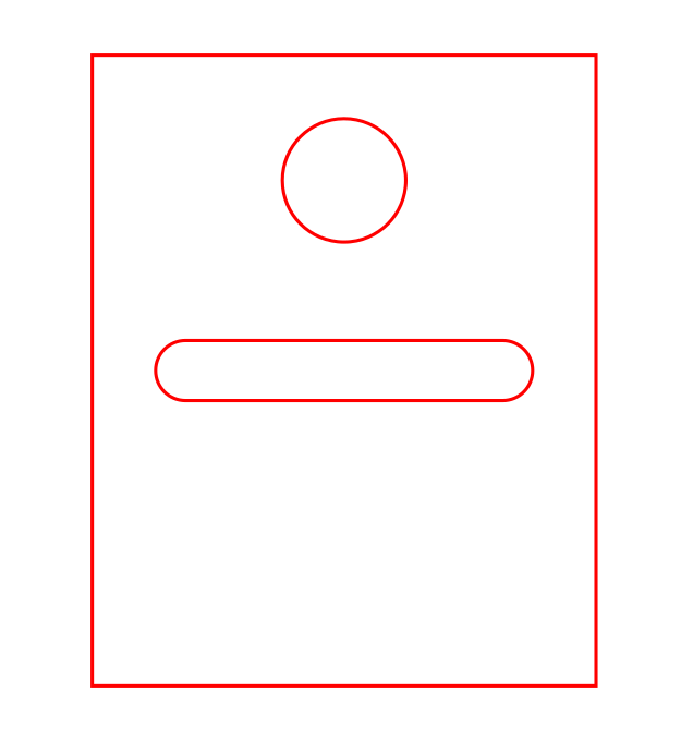
La logiciel principalement utilisé pour la découpe laser est le logiciel **Inkscape**. Afin que le dessin réalisé soit exploitable, il faut s'assurer que l'épaisseur du trait soit toujours de 1px. En ce qui concerne la couleur des traits, le rouge correspond à la découpe alors que le noir fait référence à la gravure. Le plus important lors de l'utilisation de ce logiciel est de contrôler les dimensions et le positionnement des différents objets. Le format lu par les découpes laser est le **format SVG**.

Nous avons réalisé ce dessin lors de notre découverte du logiciel.

[![screenshot-20230206-101417.png](https://wiki.fablab.sorbonne-universite.fr/BookStack/uploads/images/gallery/2023-03/scaled-1680-/screenshot-20230206-101417.png)](https://wiki.fablab.sorbonne-universite.fr/BookStack/uploads/images/gallery/2023-03/screenshot-20230206-101417.png)

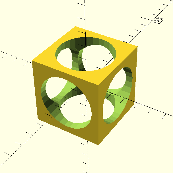
Nous avons ensuite été initiées à 2 logiciels de modélisation 3D : **OpenSCAD** et **FreeCAD**. Ces logiciels sont utilisés dans le cadre d'impressions 3D. Pour cela, il est important de savoir que le format lu par les imprimantes est le **format STL**. Nous nous limiterons à l'utilisation du workbench **Part** dans FreeCAD. Afin de se familiariser avec les outils des deux logiciels, nous avons essayé de réaliser un cube de 50mm de côté troué par 3 cylindres de 20mm de diamètre.

Sur OpenSCAD :

```C++
difference() {
    cube(50,center=true);
    translate([0,0,-25]) cylinder(h=50,r=20);
    rotate([90,0,0]) translate([0,0,-25]) cylinder(h=50,r=20);
    rotate([0,90,0]) translate([0,0,-25]) cylinder(h=50,r=20);
}
```

[![cylindrical cube.png](https://wiki.fablab.sorbonne-universite.fr/BookStack/uploads/images/gallery/2023-02/scaled-1680-/cylindrical-cube.png)](https://wiki.fablab.sorbonne-universite.fr/BookStack/uploads/images/gallery/2023-02/cylindrical-cube.png)

Nous avons ensuite pu voir un peu plus en détails comment faire fonctionner les différentes machines du FABLAB.

Pour les imprimantes 3D, le logiciel utilisé est **IdeaMaker**. Il est toujours important de réfléchir au remplissage d'un objet lors de son impression. Il faut aussi penser à l'épaisseur du fil utilisé (+ c'est fin + c'est précis mais + c'est long), à l'orientation de l'objet sur le support.

</details></div></div><details id="bkmrk-s%C3%A9ance-4-%3A-prototypa"><summary>Séance 4 : Prototypage électronique</summary>

Aujourd'hui, nous avons exploré un peu plus en profondeur le prototypage électronique avec un **M5Stack**.

Le M5Stack est un boîtier programmable avec **Arduino IDE**, contenant de la mémoire (4Mo), une carte SD et des haut-parleurs. Une sortie I2C permet d'y brancher des capteurs et un port USB-C pour le relier à un ordinateur.

Nous avons commencé par tenter de faire fonctionner le M5Stack avec des programmes exemples trouvés sur GitHub.

En téléchargeant [ce fichier ZIP](https://github.com/m5stack/M5Stack), on accède à la bibliothèque du M5Stack. Nous avons tout d'abord ouvert le programme "Hello World" (examples &gt; basics). Il ne faut pas oublier de sélectionner la board M5Stack Core ESP32 dans Arduino INE ainsi que le bon port.

Nous avons ensuite essayé d’afficher les données d’un capteur de température et d’humidité sur l’écran du M5Stack.

on a téléchargé le fichier ZIP du M5stack puis dans examples &gt; advanced &gt; display &gt; free font demo &gt; on ouvre direct le fichier

```C
#include <Arduino.h>
#include <M5Stack.h>
#include <Wire.h>
#include "SHT31.h"
#include "Free_Fonts.h" 
 
SHT31 sht31 = SHT31();
 
void setup() {  
  Serial.begin(9600);
  while(!Serial);
  Serial.println("begin...");  
  sht31.begin();  
  M5.begin();        // Init M5Core.  初始化 M5Core
  M5.Power.begin();  // Init Power module.  初始化电源模块
    
}
 
void loop() {
  float temp = sht31.getTemperature();
  float hum = sht31.getHumidity();
  M5.Lcd.setFreeFont(FSB18);
  M5.Lcd.print("Temp = ");
  M5.Lcd.print(temp);
  M5.Lcd.println(" C");
  M5.Lcd.print("Hum = ");
  M5.Lcd.print(hum);
  M5.Lcd.println(" %");
  M5.Lcd.println(); 
  delay(1000);
}
```

</details>### **<span style="color: #c2e0f4;">Projet final  
</span>**

#### <span style="text-decoration: underline;"><span style="color: #c2e0f4; text-decoration: underline;">  
Séance 5 : Première idée de projet final</span></span>

Nous avons commencé à réfléchir au projet que nous souhaiterions réaliser. Après être tombées sur [ce Tiktok](https://vm.tiktok.com/ZGJadSnxK/), nous avons convenu d'inclure des capteurs de son et des LEDs dans notre projet. Nous voulions à l'origine tenter de reproduire l'objet de la vidéo, avant de vite nous rendre compte que c'était un objet encore bien trop complexe pour nos capacités. Nous avons alors cherché sur Internet des projets utilisant quand même des micros et des LEDs, tout en restant à notre niveau novice. En voici quelques-uns :

- [Music / hand controlled led strip with arduino](https://projecthub.arduino.cc/arpi0714/de28feb6-215d-4b69-9426-aea24af7babd)
- [Neopixel Ws2812 Rainbow LED Glow With M5stick-C](https://www.instructables.com/Neopixel-Ws2812-Rainbow-LED-Glow-With-M5stick-C-Ru/)

À partir de là, nous avons décidé que le but de notre projet serait de contrôler la couleur et la luminosité de LEDs en fonction de la fréquence et l'intensité sonore (donc par exemple avec de la musique).

Nous avons commencé à travailler avec 3 composants :

- un [capteur de son](https://wiki.seeedstudio.com/Grove-Sound_Sensor/) (micro constitué d'une membrane qui vibre en fonction de la pression acoustique et qui convertit les oscillations en signal électrique)
- un [capteur de sonie](https://wiki.seeedstudio.com/Grove-Loudness_Sensor/) (micro qui isole et amplifie les signaux à haute fréquence)
- une [barre de LED](https://wiki.seeedstudio.com/Grove-RGB_LED_Stick-10-WS2813_Mini/) (10 LEDs RGB indépendantes les unes des autres)

Dans un premier temps, nous avons testé un à un chacun des composants pour comprendre leur fonctionnement.

Nous avons réussi à faire fonctionner les LEDs grâce au [code de "Seeedstudio"](https://wiki.seeedstudio.com/Grove-RGB_LED_Stick-10-WS2813_Mini/) :

```C
// NeoPixel Ring simple sketch (c) 2013 Shae Erisson
// released under the GPLv3 license to match the rest of the AdaFruit NeoPixel library

#include "Adafruit_NeoPixel.h"
#ifdef __AVR__
  #include <avr/power.h>
#endif

// Which pin on the Arduino is connected to the NeoPixels?
// On a Trinket or Gemma we suggest changing this to 1
#define PIN            6

// How many NeoPixels are attached to the Arduino?
#define NUMPIXELS      10

// When we setup the NeoPixel library, we tell it how many pixels, and which pin to use to send signals.
// Note that for older NeoPixel strips you might need to change the third parameter--see the strandtest
// example for more information on possible values.
Adafruit_NeoPixel pixels = Adafruit_NeoPixel(NUMPIXELS, PIN, NEO_GRB + NEO_KHZ800);

int delayval = 500; // delay for half a second

void setup() {
  // This is for Trinket 5V 16MHz, you can remove these three lines if you are not using a Trinket
#if defined (__AVR_ATtiny85__)
  if (F_CPU == 16000000) clock_prescale_set(clock_div_1);
#endif
  // End of trinket special code
  pixels.setBrightness(255);
  pixels.begin(); // This initializes the NeoPixel library.
}

void loop() {

  // For a set of NeoPixels the first NeoPixel is 0, second is 1, all the way up to the count of pixels minus one.

  for(int i=0;i<NUMPIXELS;i++){

    // pixels.Color takes RGB values, from 0,0,0 up to 255,255,255
    pixels.setPixelColor(i, pixels.Color(0,150,0)); // Moderately bright green color.

    pixels.show(); // This sends the updated pixel color to the hardware.

    delay(delayval); // Delay for a period of time (in milliseconds).

  }
}
```

[![image00001 (4).jpeg](https://wiki.fablab.sorbonne-universite.fr/BookStack/uploads/images/gallery/2023-03/scaled-1680-/image00001-4.jpeg)](https://wiki.fablab.sorbonne-universite.fr/BookStack/uploads/images/gallery/2023-03/image00001-4.jpeg)

En effectuant différentes modifications sur le code, nous avons pu baisser la luminosité des LED ainsi que changer leur couleur.  
Pour changer la luminosité : remplacer 255 par une valeur entre 0 et 255 (ligne 29) (ici nous avons choisi 100)  
Pour changer la couleur : remplacer 0,150,0 par 3 valeurs entre 0 et 255 (RGB) (ligne 40) (ici nous avons choisi (34,117,68)

[![image00003.jpeg](https://wiki.fablab.sorbonne-universite.fr/BookStack/uploads/images/gallery/2023-03/scaled-1680-/fpIimage00003.jpeg)](https://wiki.fablab.sorbonne-universite.fr/BookStack/uploads/images/gallery/2023-03/fpIimage00003.jpeg)

Ces multiples manipulations nous permettent de mieux appréhender les fonctionnalités d'Arduino et renforcent nos compétences en informatique.

Par la suite, nous avons utilisé le code "[RGBWstrandtest](https://github.com/Seeed-Studio/Seeed_Led_Strip/tree/master/examples/RGBWstrandtest)" afin d'afficher différentes couleurs sur les LED et obtenir un résultat similaire à celui-ci :

[![test20181210_162208.gif](https://wiki.fablab.sorbonne-universite.fr/BookStack/uploads/images/gallery/2023-03/test20181210-162208.gif)](https://wiki.fablab.sorbonne-universite.fr/BookStack/uploads/images/gallery/2023-03/test20181210-162208.gif)

À force de chercher des projets qui ressemblent au nôtre afin de nous baser sur l'un d'entre eux comme point de départ, nous nous sommes rendues compte que cela n'allait pas être facile. En effet, même si l'idée de contrôler des LEDs avec un capteur sonore a été visitée et revisitée, les projets que l'on trouve sur Internet utilise tous des composants différents des nôtres. Il est très certainement possible de créer son propre programme à partir de tous les projets proposés mais notre niveau et le temps qui nous était donné ne nous permettaient pas de réaliser cela. Ainsi, nous ne savions pas de quel point de départ partir afin de lancer notre projet.

Néanmoins, voici une tentative de faire réagir les LEDs aux données recueillies par le capteur de son :

```C
#include "Adafruit_NeoPixel.h"
#ifdef __AVR__
    #include <avr/power.h>
#endif

#define PIN 6
#define NUMPIXELS      10
Adafruit_NeoPixel pixels = Adafruit_NeoPixel(10, 6, NEO_GRB + NEO_KHZ800);
int loudness;

void setup()
{
    pixels.setBrightness(100);
    pixels.begin(); 
    pixels.show();
    Serial.begin(9600);
}

void loop()
{
    loudness = analogRead(0);
    Serial.println(loudness);
    delay(200);
    for (int i = 0; i < NUMPIXELS; i++) {
        pixels.setPixelColor(i, pixels.Color(0, 150, 0));
        pixels.show(); // This sends the updated pixel color to the hardware.
        delay(500); // Delay for a period of time (in milliseconds).
    }
}
```

####   


#### <span style="text-decoration: underline;"><span style="color: #c2e0f4; text-decoration: underline;">Séances 6 à 9 : Le sonomètre portatif</span></span>

Nous nous sommes rendues compte que notre projet de base, qui était de faire réagir des LEDs à du son, nous paraîssait au-delà de nos capacités. Nous avons donc décidé de partir sur un projet plus simple, en restant dans le thème de l'intensité sonore.

**Notre projet est donc de réaliser un <span style="text-decoration: underline;">sonomètre portatif</span> destiné aux étudiants qui ont tendance à passer beaucoup de temps dans les bars, boîtes de nuit, concerts, etc...**

##### **<span style="color: #c2e0f4;">Programmation</span>**

**Matériel :**

- [M5Stack Core](https://docs.m5stack.com/en/core/basic)
- [module PLUS](https://docs.m5stack.com/en/module/plus)
- [capteur de son](https://wiki.seeedstudio.com/Grove-Sound_Sensor/)

Le module PLUS permet de connecter des capteurs qui se branchent en analogie ou en numérique. Cela correspond au port noir (GPIO ou port B).

La toute première étape est de réussir à afficher les données recueillies par le capteur de son sur le M5Stack. Nous nous sommes donc servies d'un code permettant d'[afficher un spectre audio](https://www.hackster.io/macsbug/audio-spectrum-display-with-m5stack-4d3e93) trouvé sur le site Hackster.io. Il a fallu modifier la valeur de "micpin" (ligne 28) de 34 à 36 pour que les données soient lues. Le code utilisé est le suivant :

```C
/* ESP8266/32 Audio Spectrum Analyser on an SSD1306/SH1106 Display
 * The MIT License (MIT) Copyright (c) 2017 by David Bird. 
 * The formulation and display of an AUdio Spectrum using an ESp8266 or ESP32 and SSD1306 or SH1106 OLED Display using a Fast Fourier Transform
 * Permission is hereby granted, free of charge, to any person obtaining a copy of this software and associated documentation files 
 * (the "Software"), to deal in the Software without restriction, including without limitation the rights to use, copy, modify, merge, 
 * publish, distribute, but not to use it commercially for profit making or to sub-license and/or to sell copies of the Software or to 
 * permit persons to whom the Software is furnished to do so, subject to the following conditions:  
 * The above copyright notice and this permission notice shall be included in all copies or substantial portions of the Software. 
 * THE SOFTWARE IS PROVIDED "AS IS", WITHOUT WARRANTY OF ANY KIND, EXPRESS OR IMPLIED, INCLUDING BUT NOT LIMITED TO THE WARRANTIES 
 * OF MERCHANTABILITY, FITNESS FOR A PARTICULAR PURPOSE AND NONINFRINGEMENT. IN NO EVENT SHALL THE AUTHORS OR COPYRIGHT HOLDERS BE 
 * LIABLE FOR ANY CLAIM, DAMAGES OR OTHER LIABILITY, WHETHER IN AN ACTION OF CONTRACT, TORT OR OTHERWISE, ARISING FROM, OUT OF OR IN 
 * CONNECTION WITH THE SOFTWARE OR THE USE OR OTHER DEALINGS IN THE SOFTWARE. 
 * See more at http://dsbird.org.uk 
*/
// https://github.com/tobozo/ESP32-8-Octave-Audio-Spectrum-Display/tree/wrover-kit
// https://github.com/G6EJD/ESP32-8266-Audio-Spectrum-Display
// https://github.com/kosme/arduinoFFT
 
 
#include "arduinoFFT.h"          // Standard Arduino FFT library 
arduinoFFT FFT = arduinoFFT();
#include <M5Stack.h>
#define SAMPLES 512              // Must be a power of 2
#define SAMPLING_FREQUENCY 40000 
// Hz, must be 40000 or less due to ADC conversion time.
// Determines maximum frequency that can be analysed by the FFT Fmax=sampleF/2.

int micpin = 36; //change this to 36 if you are using the fc-04
 
struct eqBand {
  const char *freqname;
  uint16_t amplitude;
  int peak;
  int lastpeak;
  uint16_t lastval;
  unsigned long lastmeasured;
};
 
eqBand audiospectrum[8] = {
  //Adjust the amplitude values to fit your microphone
  { "125Hz", 500, 0, 0, 0, 0},
  { "250Hz", 200, 0, 0, 0, 0},
  { "500Hz", 200, 0, 0, 0, 0},
  { "1KHz",  200, 0, 0, 0, 0},
  { "2KHz",  200, 0, 0, 0, 0},
  { "4KHz",  100, 0, 0, 0, 0},
  { "8KHz",  100, 0, 0, 0, 0},
  { "16KHz", 50,  0, 0, 0, 0}
};
 
unsigned int sampling_period_us;
unsigned long microseconds;
double vReal[SAMPLES];
double vImag[SAMPLES];
unsigned long newTime, oldTime;
uint16_t tft_width  = 320; // ILI9341_TFTWIDTH;
uint16_t tft_height = 240; // ILI9341_TFTHEIGHT;
uint8_t bands = 8;
uint8_t bands_width = floor( tft_width / bands );
uint8_t bands_pad = bands_width - 10;
uint16_t colormap[255]; // color palette for the band meter (pre-fill in setup)
 
void setup() {
  M5.begin();
  dacWrite(25, 0); // Speaker OFF
  M5.Lcd.fillScreen(TFT_BLACK);
  M5.Lcd.setTextColor(YELLOW, BLACK);
  M5.Lcd.setTextSize(1);
  M5.Lcd.setRotation(1);
  sampling_period_us = round(1000000 * (1.0 / SAMPLING_FREQUENCY));
  delay(2000);
  for(uint8_t i=0;i<tft_height;i++) {
    colormap[i] = M5.Lcd.color565(tft_height-i*.5, i*1.1, 0);
  }
  for (byte band = 0; band <= 7; band++) {
    M5.Lcd.setCursor(bands_width*band + 2, 0);
    M5.Lcd.print(audiospectrum[band].freqname);
  }
}
 
void loop() {
  for (int i = 0; i < SAMPLES; i++) {
    newTime = micros()-oldTime;
    oldTime = newTime;
    vReal[i] = analogRead(micpin); // A conversion takes about 1uS on an ESP32
    vImag[i] = 0;
    while (micros() < (newTime + sampling_period_us)) { 
      // do nothing to wait
    }
  }
  FFT.Windowing(vReal, SAMPLES, FFT_WIN_TYP_HAMMING, FFT_FORWARD);
  FFT.Compute(vReal, vImag, SAMPLES, FFT_FORWARD);
  FFT.ComplexToMagnitude(vReal, vImag, SAMPLES);
 
  for (int i = 2; i < (SAMPLES/2); i++){ 
    // Don't use sample 0 and only first SAMPLES/2 are usable. 
    // Each array eleement represents a frequency and its value the amplitude.
    if (vReal[i] > 1500) { // Add a crude noise filter, 10 x amplitude or more
      byte bandNum = getBand(i);
      if(bandNum!=8) {
        displayBand(bandNum, (int)vReal[i]/audiospectrum[bandNum].amplitude);
      }
    }
  }
   
  long vnow = millis();
  for (byte band = 0; band <= 7; band++) {
    // auto decay every 50ms on low activity bands
    if(vnow - audiospectrum[band].lastmeasured > 50) {
      displayBand(band, audiospectrum[band].lastval>4 ? audiospectrum[band].lastval-4 : 0);
    }
    if (audiospectrum[band].peak > 0) {
      audiospectrum[band].peak -= 2;
      if(audiospectrum[band].peak<=0) {
        audiospectrum[band].peak = 0;
      }
    }
    // only draw if peak changed
    if(audiospectrum[band].lastpeak != audiospectrum[band].peak) {
      // delete last peak
     M5.Lcd.drawFastHLine(bands_width*band,tft_height-audiospectrum[band].lastpeak,bands_pad,BLACK);
     audiospectrum[band].lastpeak = audiospectrum[band].peak;
     M5.Lcd.drawFastHLine(bands_width*band, tft_height-audiospectrum[band].peak,
                           bands_pad, colormap[tft_height-audiospectrum[band].peak]);
    }
  } 
}
 
void displayBand(int band, int dsize){
  uint16_t hpos = bands_width*band;
  int dmax = 200;
  if(dsize>tft_height-10) {
    dsize = tft_height-10; // leave some hspace for text
  }
  if(dsize < audiospectrum[band].lastval) {
    // lower value, delete some lines
    M5.Lcd.fillRect(hpos, tft_height-audiospectrum[band].lastval,
                    bands_pad, audiospectrum[band].lastval - dsize, BLACK);
  }
  if (dsize > dmax) dsize = dmax;
  for (int s = 0; s <= dsize; s=s+4){
    M5.Lcd.drawFastHLine(hpos, tft_height-s, bands_pad, colormap[tft_height-s]);
  }
  if (dsize > audiospectrum[band].peak) {
    audiospectrum[band].peak = dsize;
  }
  audiospectrum[band].lastval = dsize;
  audiospectrum[band].lastmeasured = millis();
}
 
byte getBand(int i) {
  if (i<=2 )             return 0;  // 125Hz
  if (i >3   && i<=5 )   return 1;  // 250Hz
  if (i >5   && i<=7 )   return 2;  // 500Hz
  if (i >7   && i<=15 )  return 3;  // 1000Hz
  if (i >15  && i<=30 )  return 4;  // 2000Hz
  if (i >30  && i<=53 )  return 5;  // 4000Hz
  if (i >53  && i<=200 ) return 6;  // 8000Hz
  if (i >200           ) return 7;  // 16000Hz
  return 8;
}
```

Ce programme permet donc de visualiser un spectre audio en fonction de la fréquence, or nous cherchons à visualiser l'intensité sonore. Même si nous n'avons pas utilisé ce programme par la suite, il nous a permis de comprendre comment définir le capteur dans Arduino (**pin 36**).

L'étape suivante est de configurer plusieurs réactions du M5Stack en fonction des données sonores. Le but est d'afficher différents messages de prévention pour informer l'utilisateur de son exposition au bruit.

Le code suivant permet d'afficher le message "attention" lorsque la valeur récoltée par le capteur est supérieure à 1000. Cette valeur est choisie arbitrairement pour l'instant.  
Ce programme suivant est construit à partir du code de test du [capteur de son](https://wiki.seeedstudio.com/Grove-Sound_Sensor/), ainsi que de quelques recherches qui nous ont permis d'inclure une condition "if". La valeur de la condition choisie est ici totalement arbitraire vu qu'on cherche uniquement à ce que le programme marche.

```C
#include <M5Stack.h>
const int sensor = 36;

void setup()
{
    Serial.begin(115200);
    M5.begin();
    M5.Power.begin(); 
}

void loop()
{

    long sum = 0;
    for(int i=0; i<32; i++)
    {
        sum += analogRead(sensor); // permet de lire la valeur relevée par capteur
        sum >>= 2; // divise les valeurs par un certain facteur pour ne pas avoir de trop grandes valeurs      
    }
    Serial.println(sum); // écrit la valeur dans le plotter
          
    if (sum > 1000)
    {
        M5.Lcd.clear();
        M5.Lcd.print("attention");
    }

    delay(10);

}
```

Le but de notre objet est d'afficher différents messages de prévention en fonction de l'intensité sonore. Il faut donc imposer plusieurs conditions.  
Les niveaux d'intensité sonore sont indiqués en décibels et correspondent à des temps d'exposition hebdomadaires. Dans une boîte de nuit, l'intensité sonore varie **entre 85 et 115 dB**. Voici les messages affichés par le M5Stack en fonction de l'intensité sonore :

- **<span style="color: #b96ad9;"><span style="color: #000000; background-color: #c2e0f4;">96 dB (5h d'exposition) :</span> </span>**"Tu peux encore chiller pendant 5h"
- **<span style="color: #b96ad9;"><span style="color: #000000; background-color: #c2e0f4;">103 dB (1h) :</span> </span>**"Plus qu'une heure avant l'extinction des feux"
- **<span style="color: #b96ad9;"><span style="background-color: #c2e0f4; color: #000000;">105 dB (10 min) :</span> </span>**"Le temps d'une petite clope et au revoir"
- **<span style="color: #b96ad9;"><span style="color: #000000; background-color: #c2e0f4;">115 dB (5 min) :</span> </span>**"Prends tes affaires et sors ;)"

Pour imposer différentes conditions au M5Stack, il suffit de reprendre le programme ci-dessus et d'y ajouter de nouveaux opérateurs "if".

```C
#include <M5Stack.h>
#include "Free_Fonts.h" 
const int sensor = 36;

void setup()
{
    Serial.begin(115200);
    M5.begin();
    M5.Power.begin();
}

void loop()
{
    while(1)
    {
        long sum = 0;
        for(int i=0; i<32; i++)
        {
            sum += analogRead(sensor); // permet de lire la valeur relevée par le capteur
            sum >>= 2; // divise la valeur par un certain facteur pour ne pas avoir des valeurs trop grandes
        }
       Serial.println(sum); // écrit la valeur dans le plotter

        if (sum < 100) //en dessous de 100 dB
       {
           M5.Lcd.clear();
           M5.Lcd.print("Tu peux encore chiller pendant 5h");
           delay(3000);
       }

        if (sum >= 100 && sum < 500) //entre 100 et 105 dB
       {
           M5.Lcd.clear();
           M5.Lcd.print("Plus qu'une heure avant l'extinction des feux");
           delay(3000);
       }

        if (sum >= 500 && sum < 1000) //entre 105 et 115 dB
       {
           M5.Lcd.clear();
           M5.Lcd.print("Le temps d'une petite clope");
           delay(3000);
       }

          
        if (sum >= 1000) //au dessus de 115 dB
       {
           M5.Lcd.clear();
           M5.Lcd.print("Prends tes affaires et sors ;)");
           delay(3000);
       }

       delay(10);
    }
    
}
```

Ici, les valeurs des conditions "if" ont encore une fois été choisies arbitrairement. Pour que l'objet soit réellement fonctionnel, il aurait fallu déterminer quelle plage de valeurs lues sur l'ordinateur correspond à quelle intensité sonore. On aurait pu utiliser une source de son de référence, dont on connaît l'intensité sonore, afin de "calibrer" notre capteur. Par souci de temps, nous n'avons pas pu réaliser cela.

Il faut maintenant s'occuper de la mise en forme du message affiché. Nous avons décidé de changer la couleur de l'écran en fonction de la dangerosité du niveau sonore. Nous avons aussi changer la police ainsi que la taille de la police. Toutes les modifications liées à la mise en forme sont inspirées des programmes que l'on peut trouver dans la bibliothèque du M5Stack, comme "[Free Fonts](https://github.com/m5stack/M5Stack/blob/master/examples/Advanced/Display/Free_Font_Demo/Free_Fonts.h)" ou "[Display](https://github.com/m5stack/M5Stack/blob/master/examples/Basics/Display/Display.ino)".

Voici le programme final que nous avons utilisé :

```C
#include <M5Stack.h>
#include "Free_Fonts.h" 
const int sensor = 36;

void setup()
{
    Serial.begin(115200);
    M5.begin();
    M5.Power.begin(); 
    M5.Lcd.setBrightness(100);
}

void loop()
{
    while(1)
    {
        long sum = 0;
        for(int i=0; i<32; i++)
        {
            sum += analogRead(sensor);
            sum >>= 2;
        }
       Serial.println(sum);

        if (sum < 100) //en dessous de 100 dB
       {
           M5.Lcd.clear();
           //uint16_t colorvalue = 0;
           //colorvalue = color565(0, 153, 0);
           M5.Lcd.fillScreen(GREEN); //colorvalue(0,153,0)
           M5.Lcd.drawRect(20, 20, 280, 200, WHITE); //cadre
           M5.Lcd.setTextColor(TFT_WHITE); //couleur du texte
           M5.Lcd.setTextSize(2);
           M5.Lcd.drawString("Tu peux encore chiller", 70, 108, 2);
           M5.Lcd.drawString("pendant 5h", 94, 132, 2);
           delay(3000);
       }

        if (sum >= 100 && sum < 500) //entre 100 et 105 dB
       {
           M5.Lcd.clear();
           M5.Lcd.fillScreen(YELLOW); //color565(255,213,0)
           M5.Lcd.drawRect(20, 20, 280, 200, BLACK); //cadre
           M5.Lcd.setTextColor(TFT_BLACK); //couleur du texte
           M5.Lcd.setTextSize(2);
           M5.Lcd.drawString("Plus qu'une heure avant", 70, 110, 2);
           M5.Lcd.drawString("l'extinction des feux", 90, 130, 2);
           delay(3000);
       }

        if (sum >= 500 && sum < 1000) //entre 105 et 115
       {
           M5.Lcd.clear();
           M5.Lcd.fillScreen(ORANGE); //color565(255,162,0)
           M5.Lcd.drawRect(20, 20, 280, 200, WHITE); //cadre
           M5.Lcd.setTextColor(TFT_WHITE); //couleur du texte
           M5.Lcd.setTextSize(2);
           M5.Lcd.drawString("Le temps d'une petite clope", 160, 112, 2);
           M5.Lcd.drawString("et au revoir", 160, 128, 2);
           delay(3000);
       }

          
        if (sum >= 1000) //au dessus de 115 dB
       {
           M5.Speaker.tone(1000, 500);
           M5.Lcd.clear();
           M5.Lcd.fillScreen(RED);
           M5.Lcd.drawRect(20, 20, 280, 200, WHITE); //cadre
           M5.Lcd.setTextDatum(MC_DATUM); //texte au centre
           M5.Lcd.setTextColor(TFT_WHITE); //couleur du texte
           M5.Lcd.setTextSize(2);
           M5.Lcd.drawString("Prends tes affaires et sors ;)", 160, 120, 2);
           M5.Speaker.end();
           delay(3000);
       }

       delay(10);
    }
    
}
```

#####   


##### <span style="color: #c2e0f4;">**Modélisation 3D**</span>

Shirel s'est chargée de concevoir et dessiner le packaging de notre objet. Elle a mesuré toutes les longueurs sur un M5stack de référence et les a reportées. On a donc choisi de créer un boîtier imprimé grâce a une imprimante 3D. Le choix d'une impression 3D s'est imposé de lui même. L'objet semble plus design, plus adapté à des jeunes. En découpe laser, il semblerait plus rustique (ce qui n'est pas forcément mauvais, mais ce n'est pas le but recherché).

On ferait une sorte d'ouverture permettant de laisser visible l'écran du M5 afin d'afficher les messages d'alerte.

[![image-1678705313761.png](https://wiki.fablab.sorbonne-universite.fr/BookStack/uploads/images/gallery/2023-03/scaled-1680-/image-1678705313761.png)](https://wiki.fablab.sorbonne-universite.fr/BookStack/uploads/images/gallery/2023-03/image-1678705313761.png)

Lily a commencé à modéliser sur FreeCAD la boîte qui servira à contenir le M5stack et le capteur.

Donc dans un premier temps, j'ai simplement créé un nouveau sketch dans la partie Part design. J'ai appliqué à ce sketch différentes contraintes de longueur et de symétrie pour qu'il soit dans les proportions que nous souhaitions. Par la suite, j'ai entré une protrusion afin d'obtenir une rectangle en 3D. Afin de créer une boite, il a fallu utiliser l'option "générer une coque solide" en sélectionnant la surface du dessus. Évidemment on modifie l'épaisseur de la protrusion afin que le boîte corresponde à nos mesures.

<span id="bkmrk--23" style="font-weight: normal;">![](https://lh3.googleusercontent.com/wBKFFkAyo41N8cb8duj78lrAWQyNjev-R5UCCHljV7xbBxI6Z2seEg6lwhTVMpNo1yD2D94ZO-1lYlBMCM7Fx7xM4Eyi5QyeiNvTBjSrW-_NXOvzHMA8jbkj08MFG6CfnD-yIZOrcYDVoH9kgZKjTg4Z4A=s2048)</span>

Par la suite, il a été question de dessiner le profil de l'ergo. Pour se faire, il faut créer un nouveau sketch en sélectionnant le plan XZ pour avoir la face souhaitée de profil. On fait donc "créer une arrête liée" afin d'avoir un point fixé au centre de l'arrête de la boite. Puis on peut tracer notre ergo en poly ligne. Il suffit simplement d'effectuer un triangle rectangle, auquel encore une fois, on applique des contraintes de longueur. Afin de mieux voir les arêtes et mieux me repérer, je suis passée en représentation filaire.

<span id="bkmrk--24" style="font-weight: normal;">![](https://lh3.googleusercontent.com/RUX2X8YjhdMgy9g0IWdtBpxyags9D6O3zeVZr6ZCwyQqXkoDxmihZGUkqWOFDXn4JTDPVm7lldjcdZvTB3pGdk3Xkf6Fo9A97NymJl3wrTS7WE3hueNHdkhgq7YYUoKEMIAYPHnYoQdUXGxYsGAEQ-c47A=s2048)</span>

À<span style="font-weight: normal;"> partir de ce sketch, on va donc à nouveau créer une protrusion symétrique au plan, c'est-à-dire centrée sur l'arête. Par ailleurs, il est toujours important de centrer les choses par rapport aux axes de coordonnées, le wiki du fablab le conseil notamment.</span>

<span id="bkmrk--25" style="font-weight: normal;">![](https://lh6.googleusercontent.com/BycM5G8WkG9vmlAlXDMxfZxvDkCGLB6o0HxIcGodTp2q79R8HgkUjV_3coSDynOJ4eqtimy4SCkJoJPXH-s0vtqcLlu3xVSx6AcWzEhCGsHrR8UWJX5b7udSBqlBEaMbr1yMe0leZ70ZU6Oy2xIeq_-PaA=s2048)</span>

<span style="font-weight: normal;">Par la suite, pour me faciliter la tâche, j'ai simplement "créé une fonction de symétrie" afin de dupliquer mon ergo de l'autre côté.</span>

<span id="bkmrk--26" style="font-weight: normal;">![](https://lh4.googleusercontent.com/KjwrUXEp6rNORrV3sbyId7jBBWHNZPHE6VkhHk045jn2YeTqlOmUeu_ARnFA7ISb2isxDC_EAFEYq0UvZUUSUbcS3drTi3NguHwidslA5VMNbTo7PMhGdFM644qywZTe0rCZXC-HGX_IJuWyohm-VAznBw=s2048)</span>

Pour ce qui est du couvercle, j'avais préalablement dupliqué le fond de ma boîte pour éviter de refaire un rectangle, puis une protrusion etc... J'ai donc simplement modifié les dimensions en changeant les contraintes de longueur et largeur. En effet, afin que le fond et le couvercle de la boîte se clipsent entre eux à la fin, il faut que mon couvercle soit légèrement plus grand que le fond. J'ai donc laissé 0,5 mm de chaque côté afin d'avoir de la marge.

<span id="bkmrk--27" style="font-weight: normal;">![](https://lh4.googleusercontent.com/9JkGdK49lPRFZxvKnHJY5TXqIo-PYwHy6X2_mZqops_LvO9jbdW5WNm07HlihQy3A7zM8gMhNxh6spumRQx1mV-MF5aRXERrpvEhznVMlaGTuPWEXPwhHAyKdRM2mYgSiMsW2l-N17f7uw-vyjXNjck31g=s2048)![](https://lh5.googleusercontent.com/is18esc3cOPNIkzQ3OwmkeNxtGReZIUUEr4AVX8EFPcu7EDpKXJGGQ1rpZ4GEKNSw4LyhPfYzbHv2w9WAuSsLN4W_G9cm_XDtP02H56Dr8Pf2ZRVT5bkToJE7RbDnKgLT2Vzj6z9sxQ5JpnyYxwkMem1zg=s2048)</span>

<span style="font-weight: normal;">Afin de créer l'ergo du couvercle, j'ai suivi exactement les mêmes étapes que précédemment en créant un nouveau sketch, créer une arête liée, faire un triangle rectangle en poly ligne etc... La seule différence est, qu'afin que les deux parties de la boîte se clipsent, il est nécessaire que l'ergo du couvercle soit dirigé vers l'intérieur au lieu de l'extérieur. Donc au lieu de créer une protrusion, je crée une cavité. De plus, ses dimensions doivent être légèrement plus grandes (0,5mm de plus) afin d'avoir de la marge.</span>

<span id="bkmrk--28" style="font-weight: normal;">![](https://lh4.googleusercontent.com/_cqQJ9TdD1wKbvFGrfPyDWX-NUIZYAHcMyRJ-RGW8CGhsLTU8BigwMmRPFX2QWQNf6SHAeEelHV99VHwq-Ezg0brUbhilPNzRI7wfwHLiq7Z8T9eJYloyxG5ole9dMfXzra3Su7I8couWNzaIMQgwEcNQQ=s2048)</span>

<span style="font-weight: normal;">Pareil que pour le fond, je crée une fonction de symétrie pour avoir cet ergo des deux côtés.</span>

<span id="bkmrk--29" style="font-weight: normal;">![](https://lh6.googleusercontent.com/Qf7ozJIoR3dJpogwMlSWRFbGvpzjNHnBlEK-zHgI4Jqm_Sp0M98j6OgTzFbRbPegb3DSCvQNiWmseihqATmZguA5uHaizhKcRe2HyiHlKwHtJkm-6Lr-C89k59hN80oXhBfxF0vf9FHsY6KJO9Jxqcisug=s2048)</span>

<span style="font-weight: normal;">Voici donc le rendu final de la boîte.</span>

<span id="bkmrk--30" style="font-weight: normal;">![](https://lh3.googleusercontent.com/AYbzeztClHRSRsx-5g-oFOSbAUz4f9F3eFRt6Dxjb1fiUmJqE0x4hWw9OHpwyKE4VATQ2Ql3RY5_Al-LOYLRtnB8REqG_ZSoO_zJ-j65cju8iorOc-8b0zhHZbekbVakXlQg_v-B4rqr6laT3yE89mZRGg=s2048)</span>

<span style="font-weight: normal;">Afin de ne pas avoir beaucoup de support lors de l'impression, j'ai superposé les deux parties sur le même plan.</span>

<span id="bkmrk--31" style="font-weight: normal;">![](https://lh6.googleusercontent.com/zN6jjNPtQR1kpjP6Kh8Dk0jx9jCnL2NrxqqANhaDEFD6eydkShgEC2-_GB3sIzmb90pvr6pElNmNY5meFyPZ970X7qBQVL8L952kF1S0Uddzd2Mo5G3Ea7iPg8gyMLJH806jWmFg7oHC7iImOvwuuxYtLw=s2048)</span>

J'ai donc pu passer à l'impression 3D en enregistrant mon fichier dans le modèle qui convient pour FreeCAD. Une première impression a été faite mais malheureusement, on a eu un problème avec la machine.

<span id="bkmrk--32" style="font-weight: normal;">![](https://lh4.googleusercontent.com/Ars0jFF_6bNlYsQZWlP-5KrVpyuJ_A1a0zE_gwFP5rEWTNmZ55wNOdr9yUeW0Pwcz_x88xL7HfFLg_-mOVtPzBEJ6R_EOlvbGv0e9qv-avGzsvZ3bgeukg6Ig3mu9sBb1qGluLwrDfD4skrmlkw2B4g9Vg=s2048)</span>

<span style="font-weight: normal;">L'impression finale a prit 6 heures au total et on a pu obtenir un rendu convaincant. Malheureusement, je pense que je n'avais pas pris assez de marge au niveau des dimensions du couvercle car la boîte avait du mal à se fermer, notamment avec le M5Stack dedans. </span>

<span style="font-weight: normal;">On a subit un autre échec quant à la volonté de creuser un trou dans le couvercle pour que l'on puisse voir l'écran du M5Stack à travers la boîte. L'application FreeCAD ne me permet pas d'appliquer une contrainte de longueur entre le haut de la boite et le haut de mon rectangle. Je n'ai donc pas réussi à placer mon rectangle où je le souhaitais sur le couvercle. Cette idée a donc été abandonnée. </span>

<span id="bkmrk--33" style="font-weight: normal;">![](https://lh5.googleusercontent.com/zu-cpGAvVCJMX8H_k0Elu4HU-o4gCpoexaxdZE_mbKvoI_FInU6yMIosUR8UOAoLd6H9UPXgpi6laMytpEHd8aScmLpIISbaAfJRrQ5v_4QBqYlVpSabktXT0XEtaWy_bdh7X6soYH_Lz_i8maFPnfvW1A=s2048)![](https://lh3.googleusercontent.com/RLs_p6i4pQe1Nb3ODTQ2qRRwlqJS22_Z5NGCMj7c1esiz5V-Bi4dpg38LW5fKeCbuMkPqAZ4JnFpHNkz0a9BOZlRj_T-pyw639-gDTNLxC9SgcRbcbkwb4TQyBJVlNNPISc3mfJToFK1kkxMTvfcpuMYpg=s2048)</span>

##### <span style="color: #c2e0f4;">**Fonctionnement de l'objet et possibles améliorations**</span>


Pour s'assurer de son bon fonctionnement, nous avons effectué différents tests sur notre objet. Nous avons essayé en parlant et en mettant de la musique à différents volumes. Les messages affichés par le M5Stack sont bien cohérents avec les tests effectués mais on remarque tout de même que l'objet ne semble parfois pas capter correctement les ondes sonores. Par exemple, même en collant un téléphone avec du son très fort au sonomètre, le message affiché reste celui où il n'y a pas de danger.  
De plus, notre sonomètre n'est pas très efficace car la réelle dangerosité du son est lorsque l'on reste exposé.e pendant une certaine durée. Or ici, le message de prévention s'affiche lorsque le capteur recueille une seule valeur supérieure à la limite à un instant t précis, et non sur une certaine durée. Il est possible de visualiser le message "Prends tes affaires et sors ;)" puis quelques secondes plus tard, "Plus qu'une heure avant l'extinction des feux", ce qui n'a aucun sens pour l'utilisateur.

Pour régler ce problème, il faudrait ajouter à chaque condition "if" une condition de temps, où le message s'afficherait après que le capteur ait enregistré un certain nombre de valeurs dépassant la limite imposée à des intervalles de temps petits.

En ce qui concerne la boîte, il aurait aussi fallu fixer la capteur dedans et créer un trou pour que la paroi ne fasse pas office de barrière du son, qui viendrait diminuer et fausser les valeurs.

##### <span style="color: #c2e0f4;">**Conclusion générale du projet** </span>

Cette UE est construite de manière à ce que chaque séance soit indispensable pour la création de notre objet final. Nous avons réussi à faire en sorte que le sonomètre capte un son à une intensité sonore donnée. Cependant avec plus de temps, nous aurions pu trouver le bon code, le code qui permettrait par exemple d'alerter au 110 dB exactement atteints.

De plus, nous pouvions également améliorer toute la partie modélisation. En outre, notre boîte ne se ferme pas correctement. Si on continuait l'UE, on recommencerait la modélisation avec plus de marge dans les impressions.

Finalement, le choix d'une impression 3D, ne fut pas très judicieux. Si on avait réalisé la boîte à la découpe laser, la fabrication aurait été plus rapide. Des ajustements seraient encore possibles, si nous détections des erreurs, bien que le design recherché est au rendez- vous.

##### <span style="color: #c2e0f4;">**Rendu final**</span>

<span style="color: #c2e0f4;">Messages</span>

<span style="color: #c2e0f4;">[![vert.jpeg](https://wiki.fablab.sorbonne-universite.fr/BookStack/uploads/images/gallery/2023-04/scaled-1680-/vert.jpeg)](https://wiki.fablab.sorbonne-universite.fr/BookStack/uploads/images/gallery/2023-04/vert.jpeg)[![jaune.jpeg](https://wiki.fablab.sorbonne-universite.fr/BookStack/uploads/images/gallery/2023-04/scaled-1680-/KDsjaune.jpeg)](https://wiki.fablab.sorbonne-universite.fr/BookStack/uploads/images/gallery/2023-04/KDsjaune.jpeg)[![orange.jpeg](https://wiki.fablab.sorbonne-universite.fr/BookStack/uploads/images/gallery/2023-04/scaled-1680-/orange.jpeg)](https://wiki.fablab.sorbonne-universite.fr/BookStack/uploads/images/gallery/2023-04/orange.jpeg)[![rouge.jpeg](https://wiki.fablab.sorbonne-universite.fr/BookStack/uploads/images/gallery/2023-04/scaled-1680-/rouge.jpeg)](https://wiki.fablab.sorbonne-universite.fr/BookStack/uploads/images/gallery/2023-04/rouge.jpeg)</span>

<span style="color: #c2e0f4;">Boîte</span>

<span style="color: #c2e0f4;">[![full.jpeg](https://wiki.fablab.sorbonne-universite.fr/BookStack/uploads/images/gallery/2023-04/scaled-1680-/full.jpeg)](https://wiki.fablab.sorbonne-universite.fr/BookStack/uploads/images/gallery/2023-04/full.jpeg)[![boîte.jpeg](https://wiki.fablab.sorbonne-universite.fr/BookStack/uploads/images/gallery/2023-04/scaled-1680-/boite.jpeg)](https://wiki.fablab.sorbonne-universite.fr/BookStack/uploads/images/gallery/2023-04/boite.jpeg)[![encoche 2.jpeg](https://wiki.fablab.sorbonne-universite.fr/BookStack/uploads/images/gallery/2023-04/scaled-1680-/encoche-2.jpeg)](https://wiki.fablab.sorbonne-universite.fr/BookStack/uploads/images/gallery/2023-04/encoche-2.jpeg)[![encoche 1.jpeg](https://wiki.fablab.sorbonne-universite.fr/BookStack/uploads/images/gallery/2023-04/scaled-1680-/encoche-1.jpeg)](https://wiki.fablab.sorbonne-universite.fr/BookStack/uploads/images/gallery/2023-04/encoche-1.jpeg)</span>

####   


#### <span style="color: #c2e0f4;"><u>Séance 10 : Présentation des projets</u></span>

<span style="color: #000000;"><span style="color: #c2e0f4;"><span style="color: #000000;">Lors de cette séance, nous avons assisté à la présentation des projets de chaque groupe.</span>  
<span style="color: #000000;">Voici un lien vers le support de notre présentation : [projet fablab - sonomètre portatif](https://docs.google.com/presentation/d/1txbY0TpbhfkIAVsrkYVUuy-hojCPbsqTS9rmmTB7xGs/edit?usp=sharing)</span></span></span>

### <span style="color: #c2e0f4;">**Projets personnels**</span>

<details id="bkmrk-ma%C3%AFlys-hermann--boye"><summary>Maïlys Hermann--Boyer</summary>

Réalisation d’une étoile à l’imprimante 3D &amp; de jaeminbun à la découpe-laser

page de documentation : **[Étoile &amp; jaeminbun](https://wiki.fablab.sorbonne-universite.fr/BookStack/books/petits-projets/page/etoile-jaeminbun "Étoile & jaeminbun")**

</details><div id="bkmrk--22"></div><details id="bkmrk-shirel-fellous-%C2%A02d-e"><summary>Shirel Fellous</summary>

 **[2D et 3D Shirel](https://wiki.fablab.sorbonne-universite.fr/BookStack/books/petits-projets/page/projet-perso-shirel "Projet perso Shirel")**

</details><details id="bkmrk-lily-rose-gavanon-mo"><summary>Lily-Rose Gavanon</summary>

**[Modélisations](https://wiki.fablab.sorbonne-universite.fr/BookStack/books/petits-projets/page/modelisations "Modélisations")**

</details>

# King Dong : Les Rois de la Larme (Anciennement de la Sonette)

Membre du groupe: BREZOVSEK Kylian ; BERTOLETTI Alex ; BRIENDO Alex ; CAMUS Paul

---

Nous sommes des étudiants en première année de CMI. Dans le cadre de notre UE FABLAB (LU1SXPFL) nous avons pour objectif de concevoir un projet en groupe de 4 avec comme seule obligation l’utilisation d’au moins un capteur environnemental. Cette UE est divisée en 10 séances, à l’issue desquelles nous devrons réaliser une présentation de notre projet. Pour plus d’information, nous vous renvoyons sur cette page de **[Description de l’UE](https://wiki.fablab.sorbonne-universite.fr/BookStack/books/projets-due-2022-2023/page/description-de-lue)**.

<details id="bkmrk-s%C3%A9ance-1-%3A-introduct"><summary>Séance 1 : Introduction au FabLab</summary>

**<span style="text-decoration: underline;">Séance 1 :</span>** Nous avons découvert les locaux du **FabLab** et ses origines ainsi que l'état d'esprit de partage mis en place par son créateur **Neil Gershenfeld**. Nous avons ensuite commencé à réfléchir à notre idée de projet sur le thème des capteurs. Nous nous orientons pour l'instant vers un appareil qui serait utile dans le cadre de la pratique de la **plongée sous-marine**. Il s'agit d'un boîtier **waterproof**, que nous ferions le plus petit possible, contenant des capteurs de **pression**, de **température** et un **GPS** si nous arrivons à bien optimiser l'espace.

</details><details id="bkmrk-s%C3%A9ance-2-%3A-d%C3%A9couvert"><summary>Séance 2 : Découverte de l'Arduino</summary>

**<span style="text-decoration: underline;">Séance 2:</span>** La séance a commencé par un **historique de l'électronique**. De l'électromagnétisme à la micro-électronique actuelle, le monde de l'électronique s'est vu transformé par les physiciens au fil du temps. Nous avons été introduits à la carte **Arduino**, qui apporte une approche plus simple au prototypage que les circuits gravés. Au cours de travaux pratiques, nous avons découvert le **langage Arduino**, notamment les fonctions **setup** pour l'initialisation et **loop** pour faire une boucle. Aussi, nous savons maintenant où trouver des **bibliothèques spécifiques** et les importer afin de réaliser des tâches.

Afin de nous familiariser avec la carte Arduino, nous avons essayer d’y brancher plusieurs composants avec des **branchements groves**. Ces branchements sont des **plus robustes que les câbles Dupont** initialement utilisés et empêchent la mise en court circuit de la carte et ainsi endommager celle-ci. Dans un premier temps, nous y avons branché un capteur de température et d’humidité (comme l’image 1). Pour en extraire les données, il faut tout d’abord **importer une bibliothèque** qui va permettre de comprendre le code qui nous et ainsi d’afficher les données obtenues par le capteur sur la console.

[![image-1676308665435.jpeg](https://wiki.fablab.sorbonne-universite.fr/BookStack/uploads/images/gallery/2023-02/scaled-1680-/image-1676308665435.jpeg)](https://wiki.fablab.sorbonne-universite.fr/BookStack/uploads/images/gallery/2023-02/image-1676308665435.jpeg)

Ensuite, nous y avons branché un écran LCD (image 2) et avons répété le protocole précédent. Toutefois, la bibliothèque disponible sur **GitHub** n’était pas fonctionnelle.

![image-1675253346192.jpeg](https://wiki.fablab.sorbonne-universite.fr/BookStack/uploads/images/gallery/2023-02/scaled-1680-/image-1675253346192.jpeg)

</details><details id="bkmrk-s%C3%A9ance-3-%3A-mod%C3%A9lisat"><summary>Séance 3 : Modélisation 2D et 3D</summary>

**<span style="text-decoration: underline;">Séance 3 :</span>** Lors de cette troisième séance, nous avons découvert les différentes manières de **modéliser** un objet aussi bien en deux qu'en trois dimensions afin de pouvoir ensuite le faire confectionner par une machine (graveur laser et imprimante 3D).

Afin de modéliser en deux dimensions, nous avons utilisé le logiciel de dessin vectoriel [**Inkscape**](https://inkscape.org/fr/) permettant de générer des **fichiers SVG** exploitables directement par les graveurs laser. Conventionnellement, on dessine en <span style="text-decoration: underline;"><span style="color: #e03e2d; text-decoration: underline;">rouge</span></span> les contours que nous souhaitons voir découpés et en <span style="text-decoration: underline;"><span style="color: #000000; text-decoration: underline;">noir</span></span> ceux que nous souhaitons voir gravés, le tout toujours avec des **traits d'un pixel d'épaisseur**.

![image-1675773382143.png](https://wiki.fablab.sorbonne-universite.fr/BookStack/uploads/images/gallery/2023-02/scaled-1680-/image-1675773382143.png)

Dans le but de modéliser des objets en 3 dimensions, nous avons utilisé deux logiciels :

- **[OpenSCAD](https://openscad.org/)** qui nous permet de modéliser en utilisant du code de la forme ```C
    translate([0, 50, 0] cylinder(h = 50, r =100));
    ```
    
    <span style="color: #5217e9;"> <span style="color: #000000;">et pour lequel il existe une ["cheat sheet"](https://openscad.org/cheatsheet/)</span>  
    </span>
- **[FreeCAD](https://www.freecad.org/?lang=fr)**, dont on utilisera surtout le workbench "<span style="text-decoration: underline;">Part</span>"

Il est important de noter qu'il existe des banques de modèles 2D et 3D tels que **Thingiverse** (3D)

Nous avons également vu en fin de séance comment opérer les machines que nous utiliserons lors de notre projet, notamment via le logiciel **IdeaMaker** pour les imprimantes 3D

</details><details id="bkmrk-s%C3%A9ance-4-%3A-prototypa"><summary>Séance 4 : Prototypage du M5Stack</summary>

<span style="text-decoration: underline;">**Séance 4 :**</span> Au cours de cette séance, nous avons approfondi nos compétences préalablement acquises en **prototypage**. Nous avons premièrement testé le programme **"Hello World"** obtenu sur [GitHub](https://github.com/m5stack/M5Stack/blob/master/examples/Basics/HelloWorld/HelloWorld.ino) et utilisé sur un **M5Stack Core-ESP32**.

Nous avons ensuite téléchargé [l'ensemble des fichiers GitHub liés au M5Stack](https://github.com/m5stack/M5Stack/archive/refs/heads/master.zip). Puis, nous avons paramétré un M5Stack afin qu'il **affiche** la température et le pression mesurée par un capteur [SHT31](https://www.arduino.cc/reference/en/libraries/sht31/).

```C
#include <M5Stack.h>
#include <Arduino.h>
#include <Wire.h>
#include "SHT31.h"
#include <Wire.h>
#include "rgb_lcd.h"
SHT31 sht31 = SHT31();
void setup() {
    M5.begin();        
    M5.Power.begin(); 

    sht31.begin();
    
    M5.Lcd.print("Affichage pression et température"); 
}

void loop() {
  float temp = sht31.getTemperature();
  float hum = sht31.getHumidity();
  M5.lcd.print("Temp = "); 
  M5.lcd.print(temp);
  M5.lcd.println(" C"); //The unit for  Celsius because original arduino don't support speical symbols
  M5.lcd.print("Hum = "); 
  M5.lcd.print(hum);
  M5.lcd.println("%"); 
  M5.lcd.println();
  delay(1000);
      
    M5.lcd.setCursor(0, 0);  
    M5.lcd.print("Temp     = ");      
   M5.lcd.print(sht31.getTemperature());
    M5.lcd.setCursor(0, 1);
    M5.lcd.print("Humidity = ");    

    // print the number of seconds since reset:
    M5.lcd.print(sht31.getHumidity());
    
    delay(2000);

}
```

Nous avons ensuite modifié ce code afin d'afficher les données avec une **police différente** (plus grande et jaune) grâce au pack **"Free Font"** obtenu sur GitHub :

```C
#include <M5Stack.h>
#include <Arduino.h>
#include <Wire.h>
#include "SHT31.h"
#include <Wire.h>
#include "rgb_lcd.h"
#include <M5Stack.h>
#include "Free_Fonts.h"
SHT31 sht31 = SHT31();

void setup() {
    M5.begin();        
    M5.Power.begin(); 
    sht31.begin();
  
}

void loop() {
  M5.lcd.clear();
  int xpos = 0;
  int ypos = 40;  
  M5.Lcd.setFreeFont(FSB9);
  M5.Lcd.println(); 
  M5.Lcd.setTextColor(TFT_YELLOW);
  M5.Lcd.setCursor(xpos, ypos);
  float temp = sht31.getTemperature();
  float hum = sht31.getHumidity();
  M5.lcd.print("Temp = "); 
  M5.lcd.print(temp);
  M5.lcd.println(" C"); //The unit for  Celsius because original arduino don't support speical symbols
  M5.lcd.print("Hum = "); 
  M5.lcd.print(hum);
  M5.lcd.println("%"); 
  M5.lcd.println();
  delay(500);
      
    M5.lcd.setCursor(0, 0);  
    M5.lcd.print("Temp     = ");      
   M5.lcd.print(sht31.getTemperature());
    M5.lcd.setCursor(0, 1);
    M5.lcd.print("Humidity = ");    
    delay(1000);
}
```

Le résultat obtenu est le suivant :

![image-1678028435289.png](https://wiki.fablab.sorbonne-universite.fr/BookStack/uploads/images/gallery/2023-03/scaled-1680-/image-1678028435289.png)

Lors de la suite de la séance, nous avons chacun entreprit la modélisation de deux objets : un en 2 dimensions et un autre en 3.

</details><details id="bkmrk-s%C3%A9ance-4-bis-%3A-petit"><summary>Séance 4 bis : Petits projets : Découverte impression 3D et découpe laser</summary>

<span style="text-decoration: underline; background-color: #e03e2d;">**Projet avec graveuse/découpeuse laser :**</span>

<span style="text-decoration: underline;">**Nom :** </span>BREZOVSEK Kylian : [Projet carte à jouer e... | Wiki FablabSU (sorbonne-universite.fr)](https://wiki.fablab.sorbonne-universite.fr/BookStack/books/petits-projets/page/projet-carte-a-jouer-en-bois)

<span style="text-decoration: underline;">**Nom :** </span>BRIENDO Alex : [https://wiki.fablab.sorbonne-universite.fr/BookStack/books/petits-projets/page/chapeau-de-luffy-le-pirate-et-cercle-de-transmutation](https://wiki.fablab.sorbonne-universite.fr/BookStack/books/petits-projets/page/chapeau-de-luffy-le-pirate-et-cercle-de-transmutation)

<span style="text-decoration: underline;">**Nom :** </span>CAMUS Paul

J’ai eu l’idée de faire graver cette citation du film Astérix et Obélix : Mission Cléopatre : « Vous savez, moi je ne crois pas qu'il y ait de bonne ou de mauvaise situation. Moi, si je devais résumer ma vie aujourd'hui avec vous, je dirais que c'est d'abord des rencontres. Des gens qui m'ont tendu la main, peut-être à un moment où je ne pouvais pas, où j'étais seul chez moi. Et c'est assez curieux de se dire que les hasards, les rencontres, forgent une destinée... Parce que quand on a le goût de la chose, quand on a le goût de la chose bien faite, le beau geste, parfois on ne trouve pas l'interlocuteur en face je dirais, le miroir qui vous aide à avancer. Alors ça n'est pas mon cas, comme je disais là, puisque moi au contraire, j'ai pu : et je dis merci à la vie, je lui dis merci, je chante la vie, je danse la vie... je ne suis qu'amour ! Et finalement, quand beaucoup de gens aujourd'hui me disent « Mais comment fais-tu pour avoir cette humanité ? », et bien je leur réponds très simplement, je leur dis que c'est ce goût de l'amour ce goût donc qui m'a poussé aujourd'hui à entreprendre une construction mécanique, mais demain qui sait ? Peut-être simplement à me mettre au service de la communauté, à faire le don, le don de soi... ».

J’ai ensuite décidé de donner au **contreplaqué** la forme d’un **parchemin/papyrus** afin de rappeler l’Égypte, lieu où le film se déroule.

Pour ce faire, j’ai utilisé le logiciel **Inkscape** qui permet de dessiner en 2D n’importe quel objet. Par convention, la découpeuse laser sait que lorsqu’un trait est<span style="color: #e03e2d;"> rouge</span>, il faut <span style="color: #e03e2d;">découper</span> et lorsqu’il est **<span style="color: #000000;">noir</span>**, il faut **graver**. J’ai rencontré un **seul véritable problème** : <span style="text-decoration: underline;">assigner 2 couleurs différentes à un seul et même trait</span>. Pour palier à ce problème, j’ai voulu trouver le moyen de sectionner mon trait en 2. Grâce à Stéphane du FABLAB, que je remercie, j’ai découvert la touche qui permet de **séparer 2 noeuds** d’une même ligne ; ensuite il fallait **sélectionner tous les noeuds** de l’objet que je voulais colorer d’une autre couleur puis les <span style="text-decoration: underline;">couper</span> (CTRL+X) et les <span style="text-decoration: underline;">coller</span> afin de recréer un objet à part entière. Le résultat finale est le suivant :

[![image-1676392031484.png](https://wiki.fablab.sorbonne-universite.fr/BookStack/uploads/images/gallery/2023-02/scaled-1680-/image-1676392031484.png)](https://wiki.fablab.sorbonne-universite.fr/BookStack/uploads/images/gallery/2023-02/image-1676392031484.png)

Enfin, afin de pourvoir utiliser la découpeuse, il faut enregistrer l’image de notre objet en **SVG** en obtenant ainsi :

[![image-1676392033739.png](https://wiki.fablab.sorbonne-universite.fr/BookStack/uploads/images/gallery/2023-02/scaled-1680-/image-1676392033739.png)](https://wiki.fablab.sorbonne-universite.fr/BookStack/uploads/images/gallery/2023-02/image-1676392033739.png)

Je suis ensuite passé à l’utilisation de la découpeuse laser. J’ai utilisé celle-ci :

[![image-1676882884371.png](https://wiki.fablab.sorbonne-universite.fr/BookStack/uploads/images/gallery/2023-02/scaled-1680-/image-1676882884371.png)](https://wiki.fablab.sorbonne-universite.fr/BookStack/uploads/images/gallery/2023-02/image-1676882884371.png)

[![image-1676882849644.png](https://wiki.fablab.sorbonne-universite.fr/BookStack/uploads/images/gallery/2023-02/scaled-1680-/image-1676882849644.png)](https://wiki.fablab.sorbonne-universite.fr/BookStack/uploads/images/gallery/2023-02/image-1676882849644.png)

Clara, que je remercie aussi, m’a aidé à **paramétrer la découpeuse** en déplaçant la pointe du laser mais aussi en **réglant numériquement** mon objet. Pour le support, j’ai utilisé une chute de **contreplaqué en 6mm**. J’ai donc adapté la taille de mon objet en fonction de la place disponible sur la chute. J’ai ensuite lancé l’impression qui a commencé par graver le texte puis a terminé en découpant le bois.

[![image-1676882911305.png](https://wiki.fablab.sorbonne-universite.fr/BookStack/uploads/images/gallery/2023-02/scaled-1680-/image-1676882911305.png)](https://wiki.fablab.sorbonne-universite.fr/BookStack/uploads/images/gallery/2023-02/image-1676882911305.png)

Le résultat est au dessus de mes attentes, la découpeuse est étonnement **précise.**

[![image-1676882943875.png](https://wiki.fablab.sorbonne-universite.fr/BookStack/uploads/images/gallery/2023-02/scaled-1680-/image-1676882943875.png)](https://wiki.fablab.sorbonne-universite.fr/BookStack/uploads/images/gallery/2023-02/image-1676882943875.png)

<span style="text-decoration: underline;">**Nom:** </span>Alexandre Bertoletti

<span style="font-weight: 400;">Dans un premier temps, j’ai eu l’idée de me créer une règle graduée de 10 cm avec une image de mon choix dessus. </span>

<span style="font-weight: 400;">J’ai utilisé **Inkscape** pour réaliser ce projet, me permettant de dessiner en 2D. La tâche la plus longue pour une règle était de la gradué de manière précise. Pour commencer, j’ai tracé un rectangle de **15x5 cm** pour laisser une marge de **2,5 cm entre le bord et le premier et dernier trait**. Puis, avec le système précis de mesures d’Inkscape j’ai pu tracer les graduation une par une en changeant manuellement la position de tel sorte qu’elle soient positionnées à 1 mm d’interval, en prenant soin de tracer ceux correspondant à 0,5 et 1 cm un peu plus long des graduations de 0,1 mm pour des soucis de lisibilité</span>

<span style="font-weight: 400;">.[![image-1679900039180.png](https://wiki.fablab.sorbonne-universite.fr/BookStack/uploads/images/gallery/2023-03/scaled-1680-/image-1679900039180.png)](https://wiki.fablab.sorbonne-universite.fr/BookStack/uploads/images/gallery/2023-03/image-1679900039180.png)</span>

<span style="font-weight: 400;">Ensuite pour remplir et décorer cette règle j’ai utilisé le système de vectorisation d’une image dans Inkscape qui permet de passer d’une photo à une **image vectorielle noir**, lisible par une mach</span><span style="font-weight: 400;">ine à découpe laser. </span>

<span style="font-weight: 400;">[![Capture d’écran 2023-03-27 à 08.47.54.png](https://wiki.fablab.sorbonne-universite.fr/BookStack/uploads/images/gallery/2023-03/scaled-1680-/capture-decran-2023-03-27-a-08-47-54.png)](https://wiki.fablab.sorbonne-universite.fr/BookStack/uploads/images/gallery/2023-03/capture-decran-2023-03-27-a-08-47-54.png)</span>

<span style="font-weight: 400;">La machine a pu lire ma réalisation sans problème et mon objet a été découper et réalisé parfaitement. </span>

<span style="text-decoration: underline; background-color: #e03e2d;">**Projet avec imprimante 3D :**</span>

<span style="text-decoration: underline;">**Nom :** </span>BREZOVSEK Kylian : [Projet impression 3D clé | Wiki FablabSU (sorbonne-universite.fr)](https://wiki.fablab.sorbonne-universite.fr/BookStack/books/petits-projets/page/projet-impression-3d-cle)

<span style="text-decoration: underline;">**Nom :** </span>CAMUS Paul

J’ai eu l’idée de **modéliser 2 pièces de Lego avec le logiciel Freecad** afin de pouvoir les emboîter.

Dans un premier temps, j’ai procédé à la modélisation de ma pièce en utilisant l’outil **« sketch »** permettant de dessiner une forme en 2D et d’ensuite pouvoir lui donner une épaisseur. J’ai choisi de faire **2 pièces avec 8 tétons** pour m’assurer qu’elles tiennent bien ensemble. Puis, grâce à l’outil **cavité**, j’ai pu modifier la forme de mon rectangle d’origine.

Les **dimensions** de ma piece sont les suivantes :

\- <span style="text-decoration: underline;">Pavé</span> : longueur = 31,8mm ; largeur = 15,8mm ; hauteur = 9,6mm

\- <span style="text-decoration: underline;">8 Tétons supérieurs</span> : rayon = 1,2mm ; distance par rapport au bord du pavé le plus proche = 4mm ; hauteur = 1,8mm

\- <span style="text-decoration: underline;">Cavité principale</span> : longueur = 30,6mm ; largeur = 14,6mm ; hauteur = 8,6mm

\- *3 Tétons inférieurs* : rayon = 3,255mm ; distance par rapport au bord du pavé le plus proche = 6,8mm ; hauteur = 8,6mm

-<span style="text-decoration: underline;"> Cavités des 3 tétons inférieurs</span> : rayon = 2,4mm ; profondeur = 8,6mm

On obtient alors le rendu suivant :

[![image-1676393493987.png](https://wiki.fablab.sorbonne-universite.fr/BookStack/uploads/images/gallery/2023-02/scaled-1680-/image-1676393493987.png)](https://wiki.fablab.sorbonne-universite.fr/BookStack/uploads/images/gallery/2023-02/image-1676393493987.png)[![image-1676393500085.png](https://wiki.fablab.sorbonne-universite.fr/BookStack/uploads/images/gallery/2023-02/scaled-1680-/image-1676393500085.png)](https://wiki.fablab.sorbonne-universite.fr/BookStack/uploads/images/gallery/2023-02/image-1676393500085.png)[![image-1676393504263.png](https://wiki.fablab.sorbonne-universite.fr/BookStack/uploads/images/gallery/2023-02/scaled-1680-/image-1676393504263.png)](https://wiki.fablab.sorbonne-universite.fr/BookStack/uploads/images/gallery/2023-02/image-1676393504263.png)

Lien du modèle 3D sous FreeCAD : [lego 3d.FCStd](https://wiki.fablab.sorbonne-universite.fr/BookStack/attachments/124)

Ensuite, il faut l’exporter en **format STL** afin que l’imprimante puisse lire le fichier. Je remercie l’étudiant en Master d’entreprenariat issu d’une licence intensive qui m’a très bien expliqué le fonctionnement du logiciel **IdeaMaker**. Sur le logiciel, on voyait qu’il était préférable **d’imprimer les pièces à l’envers**, c’est-à-dire en commençant par les 8 tétons supérieurs afin de **limiter les supports** et la **dégradation des sommets des tétons**.

[![image-1676881240142.png](https://wiki.fablab.sorbonne-universite.fr/BookStack/uploads/images/gallery/2023-02/scaled-1680-/image-1676881240142.png)](https://wiki.fablab.sorbonne-universite.fr/BookStack/uploads/images/gallery/2023-02/image-1676881240142.png)

[![image-1676883112046.png](https://wiki.fablab.sorbonne-universite.fr/BookStack/uploads/images/gallery/2023-02/scaled-1680-/image-1676883112046.png)](https://wiki.fablab.sorbonne-universite.fr/BookStack/uploads/images/gallery/2023-02/image-1676883112046.png)

Lien des fichiers finaux :

[lego 3d-Body.idea](https://wiki.fablab.sorbonne-universite.fr/BookStack/attachments/123)

[lego 3d-Body.data ](https://wiki.fablab.sorbonne-universite.fr/BookStack/attachments/122)

[lego 3d.FCStd](https://wiki.fablab.sorbonne-universite.fr/BookStack/attachments/124)

Enfin, j’ai lancé l’impression de 1h33. Le résultat finale est le suivant :

  
[![image-1676887118000.png](https://wiki.fablab.sorbonne-universite.fr/BookStack/uploads/images/gallery/2023-02/scaled-1680-/image-1676887118000.png)](https://wiki.fablab.sorbonne-universite.fr/BookStack/uploads/images/gallery/2023-02/image-1676887118000.png)

[![image-1676887131052.png](https://wiki.fablab.sorbonne-universite.fr/BookStack/uploads/images/gallery/2023-02/scaled-1680-/image-1676887131052.png)](https://wiki.fablab.sorbonne-universite.fr/BookStack/uploads/images/gallery/2023-02/image-1676887131052.png)

Après coup, j’aurais dû augmenter le rayon des 8 tétons ou alors le rayon des cavités des 3 tétons car mes briques ne s’emboîtent pas dans tous les sens.

<span style="font-weight: 400;">**<span style="text-decoration: underline;">Nom:</span>** Alexandre Bertoletti </span>

<span style="font-weight: 400;">Dans un premier temps, j’ai eu l’idée de me créer un **<span style="color: #000000;">verre miniature</span>** en voulant le rendre le plus esthétique possible. </span>

<span style="font-weight: 400;">J’ai utilisé **Freecad pour réaliser ce projet**, me permettant de réaliser aisément des objets en 3D. j’ai d’abord créé un cylindre qui serait la forme principale de mon verre avec une boule de même diamètre que j’ai unies avec l'outil **fusion** et ensuite creusé à l’aide d’une autre cylindre de diamètre inférieur avec l'outil **cut**. </span>

[![Capture d’écran 2023-02-20 à 11.28.47.png](https://wiki.fablab.sorbonne-universite.fr/BookStack/uploads/images/gallery/2023-03/scaled-1680-/capture-decran-2023-02-20-a-11-28-47.png)](https://wiki.fablab.sorbonne-universite.fr/BookStack/uploads/images/gallery/2023-03/capture-decran-2023-02-20-a-11-28-47.png)

[![image-1679901364900.png](https://wiki.fablab.sorbonne-universite.fr/BookStack/uploads/images/gallery/2023-03/scaled-1680-/image-1679901364900.png)](https://wiki.fablab.sorbonne-universite.fr/BookStack/uploads/images/gallery/2023-03/image-1679901364900.png)

<span style="font-weight: 400;">À la base de cette forme, j’y ai ajouté 3 carrés qui se superposent les uns sur les autres mais avec une différence de rotation de **60 degrés** avec lesquels j’ai fait la différence pour créer un dodécagone que j’ai incorporé à la structure composé du cylindre et de la boule en la soustrayant à celle-ci en utilisant l’outils **cut** comme précédemment. </span>

<span style="font-weight: 400;">[![Capture d’écran 2023-02-20 à 11.29.35.png](https://wiki.fablab.sorbonne-universite.fr/BookStack/uploads/images/gallery/2023-03/scaled-1680-/capture-decran-2023-02-20-a-11-29-35.png)](https://wiki.fablab.sorbonne-universite.fr/BookStack/uploads/images/gallery/2023-03/capture-decran-2023-02-20-a-11-29-35.png)</span>

<span style="font-weight: 400;">Pour finir, j’ai utilisé l'outil **chamfer** pour faire les “finitions”, donner un peu d’esthétisme au verre et qu’il soit agréable à utiliser. </span>

</details><details id="bkmrk-s%C3%A9ance-5-%3A-projet-ki"><summary>Séance 5 : Projet King Dong</summary>

<span style="text-decoration: underline;">**Séance 5 :**</span> L'objectif de cette séance était de poser les fondations du projet que nous allons entreprendre lors de cette UE. Après de nombreuses recherches sur des sites tels que **[Hackaday](https://hackaday.com/)**, nous avons décidé de nous lancer dans la conception et la réalisation d'une sonnette. Celle-ci devra remplir le cahier des charges suivant:

- Sonner lorsque l'on appuie sur son bouton
- Se mettre à filmer lorsqu'un mouvement est détecté a proximité
- Rentrer dans un pavé droit de taille 10\*10\*3 cm
- Pouvoir être accrochée à un mur

Un autre objectif, qui semble cependant plus complexe et que l'on considère donc pour l'instant comme facultatif, serait de faire en sorte que la vidéo captée par la sonnette soit consultable sur un téléphone par exemple, idéalement vient un feed en direct.

Afin de réaliser ce projet, nous avons dressé une liste du matériel nécessaire (en dehors de ce qui est déjà disponible au FabLab) et des sites où leur achat est possible au plus petit prix :

- ESP 32 Cam Module
- Capteur PIR
- Arduino Push Button
- Arduino Speaker

[https://wiki.seeedstudio.com/edge-impulse-vision-ai](https://wiki.seeedstudio.com/edge-impulse-vision-ai)

</details><details id="bkmrk-s%C3%A9ance-6-%3A-tests-des"><summary>Séance 6 : Tests des capteurs pour notre projet</summary>

**<span style="text-decoration: underline;">Séance 6 :</span>** Durant cette séance, nous avons testé deux capteurs pouvant remplir la tâche de détecter un mouvement ou une présence. Dans un premier temps, nous avons testé un capteur à ultrason : [Ultrasonic Distance Sensor](https://www.seeedstudio.com/Grove-Ultrasonic-Distance-Sensor.html) permettant de déterminer la distance entre le capteur et un objet présent devant le capteur.. Le résultat a été plutôt satisfaisant, le seul défaut pouvant être qu'il ne capte que très peu sur les côtés. Pour tester ce capteur, nous avons utilisé ce code.

```C
//Make sure to install

#include <M5Stack.h>
#include "Ultrasonic.h"

Ultrasonic ultrasonic(22);
void setup()
{
  M5.begin();
}
void loop()
{
	long RangeInInches;
	long RangeInCentimeters;

	RangeInCentimeters = ultrasonic.MeasureInCentimeters(); // two measurements should keep an interval
	M5.Lcd.setCursor(10, 0);
	M5.Lcd.print(RangeInCentimeters);//0~400cm
  //M5.Speaker.tone(RangeInCentimeters, 200);
	delay(250);
}
```

Ensuite, nous avons testé un capteur de mouvement : [Mini PIR Motion Sensor](https://www.seeedstudio.com/Grove-mini-PIR-motion-sensor-p-2930.html). Nous avons eu du mal à le faire fonctionner mais nous avons finalement [trouvé un code fonctionnel](https://github.com/m5stack/M5-ProductExampleCodes/blob/master/Unit/PIR/Arduino/pir/pir.ino). Finalement, nous pensons utiliser le capteur de mouvement qui permet d'avoir un angle plus large. Voici le code utilisé pour le test.

```C++
#include <M5Stack.h>


void setup() {
  M5.begin();
  Serial.begin(115200);
  M5.Lcd.clear(BLACK);
  M5.Lcd.setTextColor(YELLOW);
  M5.Lcd.setTextSize(2);
  M5.Lcd.setTextSize(2);
  M5.Lcd.setCursor(80, 0);
  M5.Lcd.println("PIR example");
  Serial.println("PIR example: ");
  M5.Lcd.setCursor(65, 10);
  M5.Lcd.setTextColor(WHITE);
  pinMode(36, INPUT);
}


void loop() {
  M5.Lcd.setCursor(0,25); M5.Lcd.print("Status: ");
  M5.Lcd.setCursor(0,45); M5.Lcd.print("Value: ");
 
  M5.Lcd.fillRect(95,25,200,25,BLACK);
  M5.Lcd.fillRect(95,45,200,25,BLACK);
 
  if(digitalRead(36)==1){
    M5.Lcd.setCursor(95, 25);M5.Lcd.print("Sensing");
    M5.Lcd.setCursor(95, 45);M5.Lcd.print("1");
    Serial.println("PIR Status: Sensing");
    Serial.println(" value: 1");
  }
  else{
    M5.Lcd.setCursor(95, 25);M5.Lcd.print("Not Sensed");
    M5.Lcd.setCursor(95, 45);M5.Lcd.print("0");
    Serial.println("PIR Status: Not Sensed");
    Serial.println(" value: 0");
  }
  delay(500);
  M5.update();
}

```

</details><details id="bkmrk-s%C3%A9ance-7-%3A-programma"><summary>Séance 7 : Programmation des capteurs</summary>

**<span style="text-decoration: underline;">Séance 7 :</span>**

Dans cette séance, nous avons dessiné la**[ boite de notre sonnette](https://wiki.fablab.sorbonne-universite.fr/BookStack/attachments/151)**. Grâce au site **[MakerCase](https://www.makercase.com/#/basicbox)**, nous avions juste à rentrer les dimensions de notre boite :

\- Largeur : 10cm

\- Longueur : 15cm

\- Profondeur : 7cm

Nous avons aussi rajouté 3 trous qui permettront de faire passer la caméra, le bouton et le capteur de mouvement.

Ensuite, nous devons **programmer** une sonnerie qui se déclenchera dès lors que le bouton de la sonnette sera enclenché. Pour ce faire, nous avons dans un premier temps utiliser un haut parleur, le **Arduino Speaker 1.1**, et défini une **[sonnerie](https://www.hackster.io/blackpanda856/play-music-using-arduino-uno-and-a-speaker-b94e4a)** trouvé sur **Hackster.io** avec le code

```C++
#define NOTE_B0 31
#define NOTE_C1 33
#define NOTE_CS1 35
#define NOTE_D1 37
#define NOTE_DS1 39
#define NOTE_E1 41
#define NOTE_F1 44
#define NOTE_FS1 46
#define NOTE_G1 49
#define NOTE_GS1 52
#define NOTE_A1 55
#define NOTE_AS1 58
#define NOTE_B1 62
#define NOTE_C2 65
#define NOTE_CS2 69
#define NOTE_D2 73
#define NOTE_DS2 78
#define NOTE_E2 82
#define NOTE_F2 87
#define NOTE_FS2 93
#define NOTE_G2 98
#define NOTE_GS2 104
#define NOTE_A2 110
#define NOTE_AS2 117
#define NOTE_B2 123
#define NOTE_C3 131
#define NOTE_CS3 139
#define NOTE_D3 147
#define NOTE_DS3 156
#define NOTE_E3 165
#define NOTE_F3 175
#define NOTE_FS3 185
#define NOTE_G3 196
#define NOTE_GS3 208
#define NOTE_A3 220
#define NOTE_AS3 233
#define NOTE_B3 247
#define NOTE_C4 262
#define NOTE_CS4 277
#define NOTE_D4 294
#define NOTE_DS4 311
#define NOTE_E4 330
#define NOTE_F4 349
#define NOTE_FS4 370
#define NOTE_G4 392
#define NOTE_GS4 415
#define NOTE_A4 440
#define NOTE_AS4 466
#define NOTE_B4 494
#define NOTE_C5 523
#define NOTE_CS5 554
#define NOTE_D5 587
#define NOTE_DS5 622
#define NOTE_E5 659
#define NOTE_F5 698
#define NOTE_FS5 740
#define NOTE_G5 784
#define NOTE_GS5 831
#define NOTE_A5 880
#define NOTE_AS5 932
#define NOTE_B5 988
#define NOTE_C6 1047
#define NOTE_CS6 1109
#define NOTE_D6 1175
#define NOTE_DS6 1245
#define NOTE_E6 1319
#define NOTE_F6 1397
#define NOTE_FS6 1480
#define NOTE_G6 1568
#define NOTE_GS6 1661
#define NOTE_A6 1760
#define NOTE_AS6 1865
#define NOTE_B6 1976
#define NOTE_C7 2093
#define NOTE_CS7 2217
#define NOTE_D7 2349
#define NOTE_DS7 2489
#define NOTE_E7 2637
#define NOTE_F7 2794
#define NOTE_FS7 2960
#define NOTE_G7 3136
#define NOTE_GS7 3322
#define NOTE_A7 3520
#define NOTE_AS7 3729
#define NOTE_B7 3951
#define NOTE_C8 4186
#define NOTE_CS8 4435
#define NOTE_D8 4699
#define NOTE_DS8 4978
#define REST      0
#define END -1


int melody[] = {
  NOTE_E5, NOTE_DS5, //1
  NOTE_E5,  NOTE_DS5,  NOTE_E5,  NOTE_B4,  NOTE_D5,  NOTE_C5,
  NOTE_A4,  NOTE_C4, NOTE_E4, NOTE_A4,
  NOTE_B4, NOTE_E4, NOTE_GS4, NOTE_B4,
  NOTE_C5,  REST, NOTE_E4, NOTE_E5,  NOTE_DS5,
 
  NOTE_E5, NOTE_DS5, NOTE_E5, NOTE_B4, NOTE_D5, NOTE_C5,
  NOTE_A4, NOTE_C4, NOTE_E4, NOTE_A4,
  NOTE_B4, NOTE_E4, NOTE_C5, NOTE_B4,
  NOTE_A4 , REST, END


};


// note durations: 8 = quarter note, 4 = 8th note, etc.
int noteDurations[] = {       //duration of the notes
4, 4,
4, 4, 4, 4, 4, 4,
4, 4, 4, 4,
4, 4, 4, 4,
4, 4 ,4, 4, 4,


4, 4, 4, 4, 4, 4,
4, 4, 4, 4,
4, 4, 4, 4,
1, 2, 20


};


int speed=90;  //higher value, slower notes
void setup() {


Serial.begin(9600);
for (int thisNote = 0; melody[thisNote]!=-1; thisNote++) {


int noteDuration = speed*noteDurations[thisNote];
tone(3, melody[thisNote],noteDuration*.95);
Serial.println(melody[thisNote]);


delay(noteDuration);


noTone(3);
}
}


void loop() {
}

```

</details><details id="bkmrk-s%C3%A9ance-8-%3A-cam%C3%A9ra-ai"><summary>Séance 8 : Caméra AI Module Vision</summary>

Dans cette séance, nous avons essayé de programmer la caméra AI Module vision. Nous avons dans un premier temps dû souder un Xiao sur la caméra afin de pouvoir la relier à une carte Arduino ou un M5Stack. Pour ce faire, nous avons souder une barrette femelle longue sur la carte de la caméra et une barrette droite mâle longue sur le Xiao.

[![image-1679833340462.jpeg](https://wiki.fablab.sorbonne-universite.fr/BookStack/uploads/images/gallery/2023-03/scaled-1680-/image-1679833340462.jpeg)](https://wiki.fablab.sorbonne-universite.fr/BookStack/uploads/images/gallery/2023-03/image-1679833340462.jpeg)

Une fois cela fait, nous sommes ensuite revenu sur la configuration de la caméra. Nous avons dû chercher sur de nombreux sites car cette caméra est relativement récente et la documentation sur celle-ci se fait extrêmement rare ou bien pour des applications très spécifiques. Que ce soit sur [Seed Studio](https://wiki.seeedstudio.com/Grove-Vision-AI-Module/), ou [EdgeImpulse](https://docs.edgeimpulse.com/docs/development-platforms/officially-supported-mcu-targets/seeed-grove-vision-ai), la documentation est faite à partir d’autres interfaces que l’Arduino ou le M5Stack comme le Raspberry nous rendant ainsi impossible l’exploitation de la Caméra AI Module Vision. Il semblait possible de faire fonctionner la caméra avec le XIAO, mais nous n'avons pas réussi à aboutir même en suivant rigoureusement les indications fournies. Notamment, la documentation parlait d'un logiciel nommé Bouffalo que nous n'arrivions pas à comprendre. Par ailleurs, nos capacités en informatique et en codage ne nous permettant pas de développer un code de A à Z, nous avons décidé de mettre fin au projet King Dong.

Cette séance nous a montré que la documentation est vraiment quelque chose de fondamental, c’est pourquoi nous vous avons mis tous les liens que nous avons trouvés afin de rassembler le plus d’information possible pour les prochaines personnes qui utiliseront cette caméra.

</details><details id="bkmrk-s%C3%A9ance-9-%3A-projet-al"><summary>Séance 9 : Projet Alarme Incendie : les Rois de la Larme</summary>

La décision de la séance dernière nous a obligé a changer de projet. En effet, les multiples échecs liés à la caméra AI Module Vision nous ont mené à tout repenser depuis le départ afin de rebondir promptement sur un projet nouveau dont les fondations pourraient être bâties sur les ruines du regretté empire de la sonnette que nous avions pourtant corps et âme tenté de faire fructifier.

Tout le progrès fait jusqu'alors n'était donc pas perdu : il constituerait l'armature neuve d'un projet dont l'aboutissement technique n'aura d'égal que la splendeur.

Afin de repartir, nous nous sommes questionnés quant à ce qui était à notre disposition : un code permettant de jouer de la musique et un autre permettant de faire fonctionner un capteur de mouvement PIR. Nous avons de plus trouvé parmi les nombreux capteurs à notre disposition au FabLab un détecteur de flamme. Mis face à tous ces éléments, nous eûmes une révélation salvatrice commune : celle de réaliser une double alarme, à la fois à incendie et à intrusion.

Suite à cette illumination collective, nous cherchâmes à bride abattue un [code permettant de faire fonctionner le Flame Sensor](https://wiki.seeedstudio.com/Grove-Flame_Sensor/) que nous avons su prestement et talentueusement allier au code pour le Capteur PIR (voir séance 6) et à celui pour la musique (séance 7) afin d'obtenir le code final pour notre alarme :

```C++
#define NOTE_B0 31
#define NOTE_C1 33
#define NOTE_CS1 35
#define NOTE_D1 37
#define NOTE_DS1 39
#define NOTE_E1 41
#define NOTE_F1 44
#define NOTE_FS1 46
#define NOTE_G1 49
#define NOTE_GS1 52
#define NOTE_A1 55
#define NOTE_AS1 58
#define NOTE_B1 62
#define NOTE_C2 65
#define NOTE_CS2 69
#define NOTE_D2 73
#define NOTE_DS2 78
#define NOTE_E2 82
#define NOTE_F2 87
#define NOTE_FS2 93
#define NOTE_G2 98
#define NOTE_GS2 104
#define NOTE_A2 110
#define NOTE_AS2 117
#define NOTE_B2 123
#define NOTE_C3 131
#define NOTE_CS3 139
#define NOTE_D3 147
#define NOTE_DS3 156
#define NOTE_E3 165
#define NOTE_F3 175
#define NOTE_FS3 185
#define NOTE_G3 196
#define NOTE_GS3 208
#define NOTE_A3 220
#define NOTE_AS3 233
#define NOTE_B3 247
#define NOTE_C4 262
#define NOTE_CS4 277
#define NOTE_D4 294
#define NOTE_DS4 311
#define NOTE_E4 330
#define NOTE_F4 349
#define NOTE_FS4 370
#define NOTE_G4 392
#define NOTE_GS4 415
#define NOTE_A4 440
#define NOTE_AS4 466
#define NOTE_B4 494
#define NOTE_C5 523
#define NOTE_CS5 554
#define NOTE_D5 587
#define NOTE_DS5 622
#define NOTE_E5 659
#define NOTE_F5 698
#define NOTE_FS5 740
#define NOTE_G5 784
#define NOTE_GS5 831
#define NOTE_A5 880
#define NOTE_AS5 932
#define NOTE_B5 988
#define NOTE_C6 1047
#define NOTE_CS6 1109
#define NOTE_D6 1175
#define NOTE_DS6 1245
#define NOTE_E6 1319
#define NOTE_F6 1397
#define NOTE_FS6 1480
#define NOTE_G6 1568
#define NOTE_GS6 1661
#define NOTE_A6 1760
#define NOTE_AS6 1865
#define NOTE_B6 1976
#define NOTE_C7 2093
#define NOTE_CS7 2217
#define NOTE_D7 2349
#define NOTE_DS7 2489
#define NOTE_E7 2637
#define NOTE_F7 2794
#define NOTE_FS7 2960
#define NOTE_G7 3136
#define NOTE_GS7 3322
#define NOTE_A7 3520
#define NOTE_AS7 3729
#define NOTE_B7 3951
#define NOTE_C8 4186
#define NOTE_CS8 4435
#define NOTE_D8 4699
#define NOTE_DS8 4978
#define REST      0
#define END -1

#define PIR_MOTION_SENSOR 2


int melody[] = {
  NOTE_E5, NOTE_DS5, //1
  NOTE_E5,  NOTE_DS5,  NOTE_E5,  NOTE_B4,  NOTE_D5,  NOTE_C5,
  NOTE_A4,  NOTE_C4, NOTE_E4, NOTE_A4,
  NOTE_B4, NOTE_E4, NOTE_GS4, NOTE_B4,
  NOTE_C5,  REST, NOTE_E4, NOTE_E5,  NOTE_DS5,
 
  NOTE_E5, NOTE_DS5, NOTE_E5, NOTE_B4, NOTE_D5, NOTE_C5,
  NOTE_A4, NOTE_C4, NOTE_E4, NOTE_A4,
  NOTE_B4, NOTE_E4, NOTE_C5, NOTE_B4,
  NOTE_A4 , REST, END
};

// note durations: 8 = quarter note, 4 = 8th note, etc.
int noteDurations[] = {       //duration of the notes
4, 4,
4, 4, 4, 4, 4, 4,
4, 4, 4, 4,
4, 4, 4, 4,
4, 4 ,4, 4, 4,


4, 4, 4, 4, 4, 4,
4, 4, 4, 4,
4, 4, 4, 4,
1, 2, 20
};

int melody2[] = {
  REST, NOTE_DS4,
  NOTE_E4, REST, NOTE_FS4, NOTE_G4, REST, NOTE_DS4,
  NOTE_E4, NOTE_FS4,  NOTE_G4, NOTE_C5, NOTE_B4, NOTE_E4, NOTE_G4, NOTE_B4,  
  NOTE_AS4, NOTE_A4, NOTE_G4, NOTE_E4, NOTE_D4,
  NOTE_E4, REST, END };

int noteDurations2[] = {       //duration of the notes
2, 2,
1, 2, 2, 1, 2, 2,
2, 2, 2, 2, 4, 2, 2, 2,
4 , 2, 2, 2, 4,
2, 2, 20

};

int speed=90;

// lowest and highest sensor readings:
const int sensorMin = 0;     //  sensor minimum
const int sensorMax = 1024;  // sensor maximum

void setup()  {
  pinMode(PIR_MOTION_SENSOR, INPUT);
  Serial.begin(9600);  
}
void loop() {
  // read the sensor on analog A0:
  int sensorReading  = analogRead(A0);
  // map the sensor range (four options):
  // ex: 'long  int map(long int, long int, long int, long int, long int)'
  int range = map(sensorReading,  sensorMin, sensorMax, 0, 8);
 
  // range value:
  switch (range) {
  case 0:    // A fire closer than 1.5 feet away.
    Serial.println("** Close  Fire **");
    for (int thisNote = 0; melody[thisNote]!=-1; thisNote++) {
      int noteDuration = speed*noteDurations[thisNote];
      tone(3, melody[thisNote],noteDuration*.95);
      Serial.println(melody[thisNote]);
      delay(noteDuration);
      noTone(3);
}
    break;
  case 1:    // No fire detected.
    Serial.println("No  Fire");
      break;
  case 2:    // No fire detected.
    Serial.println("No  Fire");
    break;
  case 3:    // No fire detected.
    Serial.println("No  Fire");
    break;
  case 4:    // No fire detected.
    Serial.println("No  Fire");
    break;
  case 5:    // No fire detected.
    Serial.println("No  Fire");
    break;
  case 6:    // No fire detected.
    Serial.println("No  Fire");
    break;
  case 7:    // No fire detected.
    Serial.println("No  Fire");
    break;
  }
  delay(1);  // delay between reads

  if(digitalRead(PIR_MOTION_SENSOR))//if it detects the moving people?
    for (int thisNote = 0; melody2[thisNote]!=-1; thisNote++) {
      int noteDuration2 = speed*noteDurations2[thisNote];
      tone(3, melody2[thisNote],noteDuration2*.95);
      Serial.println(melody2[thisNote]);
      delay(noteDuration2);
      noTone(3);}
  else
        Serial.println("Watching");

 delay(200);
}
```

Il est important de noter qu'en terme de branchements, il est nécessaire de brancher l'Arduino Speaker au port D3, le PIR Sensor au D2 et le Flame Sensor au A0.

Ce code nous permet alors de jouer la Lettre pour Élise de Beethoven en cas d'incendie et le cultissime générique de La Panthère Rose en cas d'intrusion. Ces deux musiques, provenant originalement d'un [GitHub](https://github.com/robsoncouto/arduino-songs) par nos soins sanctifié tant il nous a été utile, ont été longuement réadaptées de nos frêles mains note par note afin de fonctionner avec notre code et équipement.

Mais que serait le module Arduino sans sa batterie, lui procurant puissance et autonomie à toute épreuve? Dans la salle d'électronique, nous trouvâmes un réceptacle qui, à première vue, ne payait pas de mine. Cependant, une fois couplé à une triplette de pile AAA et après un branchement minutieux au module Arduino, ce dispositif laissa éclater tout son potentiel et se montra tout à fait adéquat à la réalisation de notre ambitieux projet.

[![image-1679949974951.jpg](https://wiki.fablab.sorbonne-universite.fr/BookStack/uploads/images/gallery/2023-03/scaled-1680-/image-1679949974951.jpg)](https://wiki.fablab.sorbonne-universite.fr/BookStack/uploads/images/gallery/2023-03/image-1679949974951.jpg)

Suite à ce véritable travail d'horlogerie suisse, il ne nous restait plus qu'a confectionner le digne réceptacle qui accueillerait notre merveille technique.

Lors de la séance 6, nous avions établi les plans d’une boite capable d’accueillir le désormais caduc projet King Dong. En usant du même logiciel ([MakerCase)](https://www.makercase.com/#/basicbox), nous avons designé un contenant assez noble pour accueillir cette innovation immodérément novatrice dans son domaine.[Ces plans](https://wiki.fablab.sorbonne-universite.fr/BookStack/attachments/206) à la fois complexes et puristes respectent les dimensions suivantes :

\- Largeur : 14cm

\- Longueur : 14cm

\- Profondeur : 7cm

Sublimée par l’enseigne de notre marque et accompagné de son logo, le rendu est tel que :

[![82ED022B-6C3C-4235-8389-F02C0F3D3C37.jpeg](https://wiki.fablab.sorbonne-universite.fr/BookStack/uploads/images/gallery/2023-03/scaled-1680-/82ed022b-6c3c-4235-8389-f02c0f3d3c37.jpeg)](https://wiki.fablab.sorbonne-universite.fr/BookStack/uploads/images/gallery/2023-03/82ed022b-6c3c-4235-8389-f02c0f3d3c37.jpeg)

Les capteurs nécessitant une exposition extérieure pour fonctionner, nous étions dans le besoin de créer 2 orifices. Après de nombreuses mesures, nous nous sommes arrêtés sur ce modèle :

[![684B573C-12E9-4B64-A36B-656731F07229.jpeg](https://wiki.fablab.sorbonne-universite.fr/BookStack/uploads/images/gallery/2023-04/scaled-1680-/684b573c-12e9-4b64-a36b-656731f07229.jpeg)](https://wiki.fablab.sorbonne-universite.fr/BookStack/uploads/images/gallery/2023-04/684b573c-12e9-4b64-a36b-656731f07229.jpeg)

Lors de l’assemblage final de notre prototype, Alexandre, un employé du FABLAB, gravait un QR code sur une plaque de PMMA. Nous vient alors l’idée de graver à notre tour un QR Code menant à la page Wiki de notre alarme. Pour ce faire, rien de plus simple, il suffit d'utilisé le magnifique logiciel qu'est Inkscape et d'ouvrir le menu puis de cliquer sur extensions, rendu, Code-barres et finalement QR code avant de rentrer dans la page qui s'ouvre le lien de notre parfaite documentation et le tour est joué.

![image-1680430913823.png](https://wiki.fablab.sorbonne-universite.fr/BookStack/uploads/images/gallery/2023-04/scaled-1680-/image-1680430913823.png)

Soudain, une terrible nouvelle vint s’abattre sur notre groupe. Le haut parleur décidait de faire des siennes. Après quelques rectifications, il retrouvait ses capacités. Toutefois, le vent de jeunesse qui l’animait n’était plus … le son qu’il dégageait n’était plus aussi puissant que celui d’antan. Nous vient alors l’idée de designer des trous sur une des nobles tranches de notre appareil afin de diminuer au maximum les pertes d’intensité sonore. Désormais vêtu de son illustre documentation ainsi que de splendide orifice, notre projet atteignait calmement son apogée.

[![7FF9E6B6-199E-4196-AF69-46839161AF65.jpeg](https://wiki.fablab.sorbonne-universite.fr/BookStack/uploads/images/gallery/2023-04/scaled-1680-/7ff9e6b6-199e-4196-af69-46839161af65.jpeg)](https://wiki.fablab.sorbonne-universite.fr/BookStack/uploads/images/gallery/2023-04/7ff9e6b6-199e-4196-af69-46839161af65.jpeg)

Toute bonne chose ayant une fin, l’heure de l’étape finale fut venue. Assemblant à grands coups de colle à bois pour le réceptacle et de scotch pour les composants, notre appareil fut revêtit de ses plus divins ornements en un rien de temps. Une aventure venait de prendre fin mais une légende était créée …

[![F5F05036-4BB3-4171-986A-834F7E6E24DB.jpeg](https://wiki.fablab.sorbonne-universite.fr/BookStack/uploads/images/gallery/2023-04/scaled-1680-/f5f05036-4bb3-4171-986a-834f7e6e24db.jpeg)](https://wiki.fablab.sorbonne-universite.fr/BookStack/uploads/images/gallery/2023-04/f5f05036-4bb3-4171-986a-834f7e6e24db.jpeg)

[![56E76F5E-5858-4DB2-8F05-56AE4B5BFAD3.jpeg](https://wiki.fablab.sorbonne-universite.fr/BookStack/uploads/images/gallery/2023-04/scaled-1680-/56e76f5e-5858-4db2-8f05-56ae4b5bfad3.jpeg)](https://wiki.fablab.sorbonne-universite.fr/BookStack/uploads/images/gallery/2023-04/56e76f5e-5858-4db2-8f05-56ae4b5bfad3.jpeg)

</details><details id="bkmrk-s%C3%A9ance-10-%3A-pr%C3%A9senta"><summary>Séance 10 : Présentation finale</summary>

Nous sommes dimanche après-midi, l’heure de notre soutenance arrive à grands pas. Soudain, une Visio-conférence est programmée à 15h précise. Ce n’est que 2h après que nous arrivâmes enfin à trouver un consensus. Notre projet étant, disons-le nous, relativement simpliste, il nous fallait tout miser sur notre dernière resource : l’humour. De cette décision en est ressorti ce [diaporama](https://docs.google.com/presentation/d/1oe5LLKUcTE0E6Mz7SMoMEj_IcpX3tVyX6hn_654uOxc/edit).

Il est 9h, nous sommes lundi matin, un silence d’outre-tombe règne dans le Fablab. Les soutenances se font attendre mais notre assiduité aura raison de nous. Notre groupe se trouvant être l’unique groupe au complet, notre soutenance ouvre le bal. 20 minutes plus tard, des sourires se dessinent sur tous les visages. Notre mission est un franc succès. Les Rois de la Larme ont vaincu. Néanmoins, notre présentation est jugée, à juste titre, un peu trop bâtarde entre un pitch de start up et une présentation formelle et approfondie du sujet. En effet, il aurait été préférable de se concentrer uniquement sur l’humour pour présenter notre projet en survolant très rapidement les détails les plus importants et en se concentrant sur utilisation.

[![DCC776D6-3BD3-4F53-ACB5-5D7576FD06C9.jpeg](https://wiki.fablab.sorbonne-universite.fr/BookStack/uploads/images/gallery/2023-04/scaled-1680-/dcc776d6-3bd3-4f53-acb5-5d7576fd06c9.jpeg)](https://wiki.fablab.sorbonne-universite.fr/BookStack/uploads/images/gallery/2023-04/dcc776d6-3bd3-4f53-acb5-5d7576fd06c9.jpeg)

[![5C7F4B33-EED0-4011-9564-00B89DD3E1B9.jpeg](https://wiki.fablab.sorbonne-universite.fr/BookStack/uploads/images/gallery/2023-04/scaled-1680-/5c7f4b33-eed0-4011-9564-00b89dd3e1b9.jpeg)](https://wiki.fablab.sorbonne-universite.fr/BookStack/uploads/images/gallery/2023-04/5c7f4b33-eed0-4011-9564-00b89dd3e1b9.jpeg)

[![470316B9-0388-42FC-AF72-57CF42023F9F.jpeg](https://wiki.fablab.sorbonne-universite.fr/BookStack/uploads/images/gallery/2023-04/scaled-1680-/470316b9-0388-42fc-af72-57cf42023f9f.jpeg)](https://wiki.fablab.sorbonne-universite.fr/BookStack/uploads/images/gallery/2023-04/470316b9-0388-42fc-af72-57cf42023f9f.jpeg)

[![928BC3C9-F083-4F6D-BE97-D727B3252527.jpeg](https://wiki.fablab.sorbonne-universite.fr/BookStack/uploads/images/gallery/2023-04/scaled-1680-/928bc3c9-f083-4f6d-be97-d727b3252527.jpeg)](https://wiki.fablab.sorbonne-universite.fr/BookStack/uploads/images/gallery/2023-04/928bc3c9-f083-4f6d-be97-d727b3252527.jpeg)[![684B573C-12E9-4B64-A36B-656731F07229.jpeg](https://wiki.fablab.sorbonne-universite.fr/BookStack/uploads/images/gallery/2023-04/scaled-1680-/684b573c-12e9-4b64-a36b-656731f07229.jpeg)](https://wiki.fablab.sorbonne-universite.fr/BookStack/uploads/images/gallery/2023-04/684b573c-12e9-4b64-a36b-656731f07229.jpeg)

</details>

# Groupe B3

- Membre du groupe:

**Clément BAILLY, Pierre BERNARDE, Leeloo BLEYNIE, Vitaly POPOFF**

---

<details id="bkmrk-s%C3%A9ance-1-%3A-introduct"><summary>Séance 1 : introduction de l'UE</summary>

**<span style="color: #ba372a;"><span style="font-size: x-large;">Séance 1 : introduction de l'UE</span></span><span style="font-size: x-large;"> </span>**

- **<span style="color: #000000;">Présentation globale</span> :**

**M. Dupuis nous a montré les <span style="color: #2dc26b;"><span style="color: #000000;">attendus de l'UE,, les projets à réaliser.</span></span><span style="color: #2dc26b;">  
</span>**

**<span style="color: #000000;">Nous réaliserons un projet scientifique en 10 séances</span>, en se servant de la<span style="color: #000000;"> base de données du réseau FabLab et de son outillage disponible. Cette année, le projet portera sur le thème des capteurs météo  
</span>**

- **<span style="color: #000000;">Cours sur l'histoire des FabLab</span>**

**Un *<span class="lang-en" lang="en">fab lab</span>* (contraction de l'anglais *<span class="lang-en" lang="en">fabrication laboratory</span>*, « laboratoire de fabrication ») est un tiers-lieu de type makerspace cadré par le MIT et la FabFoundation en proposant un inventaire minimal permettant la création des principaux projets fab labs, un ensemble de logiciels et solutions libres et open-sources, les Fab Modules, et une charte de gouvernance, la Fab Charter**

**Ils sont créés en 1995 par Neil Gershenfeld, et sont considérés comme très pratiques pour la communauté scientifique.**

- **<span style="color: #000000;">Visite des locaux du FabLab</span> :<span style="color: #000000;"> </span>**

**<span style="color: #000000;">Nous disposons d'imprimantes 3D, de machines de découpe et de gravure, de fraiseuses, et d'un labo d'assemblage électronique pour construire la structure de l'objet technique à concevoir. </span>**

</details><details id="bkmrk-s%C3%A9ance-2-%3A-composant"><summary>Séance 2 : composants électroniques</summary>

**<span style="color: #ba372a;"><span style="font-size: x-large;">Séance 2 : composants électroniques</span></span>**

**<span style="color: #000000;">Cours magistral de 3h sur :</span>**

- **<span style="color: #2dc26b;">les composants électroniques, le prototypage, les transistors, etc..</span>**
- **<span style="color: #ba372a;">la carte Arduino. <span style="color: #000000;"><span style="color: #34495e;">Il s'agit d'une carte connectable à la fois à un ordinateur et à différents modules<span style="color: #2dc26b;"> </span></span><span style="color: #2dc26b;">(gazomètre, thermomètre, écran, haut-parleur, détecteur de CO2, etc).</span></span></span>**

**[![image-1679845200553.png](https://wiki.fablab.sorbonne-universite.fr/BookStack/uploads/images/gallery/2023-03/scaled-1680-/image-1679845200553.png)](https://wiki.fablab.sorbonne-universite.fr/BookStack/uploads/images/gallery/2023-03/image-1679845200553.png)**

**<span style="color: #ba372a;"><span style="color: #000000;">Cette carte est très polyvalente, et son utilisation est relativement simple. Elle est plus simple et plus compacte dans un montage électronique par rapport aux fils Dupont (utilisables sur une breadboard). <span style="color: #ba372a;"><span style="color: #000000;">Elle peut être associée à différents modules, fournissant différentes informations comme la température, l'humidité de l'air, la pression, mais également des périphériques externes comme comme un haut-parleur, un buzzer, etc.</span></span> </span></span>**

**<span style="color: #ba372a;"><span style="color: #000000;">Le code sur arduino a une structure assez spécifique : il faut tout d'abord inclure les bibliothèques de code fonctionnant avec les modules utilisés (écran, capteur...) ainsi que les variables que nous voudrions utiliser après. Ensuite dans la fonction setup il faut mettre tout ce qui permet d'initialiser les composants et de les préparer au code principal ainsi que tous les codes qui sont utilisés qu'une seule fois. Pour finir il y a la fonction loop qui comme son nom l'indique permet de faire une "boucle" dans le code et donc de répéter périodiquement certaines actions.</span></span>**

**<span style="color: #ba372a;"><span style="color: #000000;">Nous avons tout d'abord voulu tester l'appareil avec un capteur d'humidité. Ce module utilise l'extension I2C, nous l'avons donc connecté à ce port de la carte, que nous avons reliés à un ordinateur. Il faut ensuite télécharger la bibliothèque associée à ce module et prendre le code d'exemple en bas de page nous permettant de voir la température ainsi que l'humidité sur le moniteur série comme ceci :</span></span>**


**[![image-1679849323530.png](https://wiki.fablab.sorbonne-universite.fr/BookStack/uploads/images/gallery/2023-03/scaled-1680-/image-1679849323530.png)](https://wiki.fablab.sorbonne-universite.fr/BookStack/uploads/images/gallery/2023-03/image-1679849323530.png)**

**Nous avons ensuite utilisé séparément un écran OLED et avons utilisé le fameux code "hello world" en bas de page pour voir comment il fonctionnait nous donnant ce résultat :**

**[![image-1679854384067.jpg](https://wiki.fablab.sorbonne-universite.fr/BookStack/uploads/images/gallery/2023-03/scaled-1680-/image-1679854384067.jpg)](https://wiki.fablab.sorbonne-universite.fr/BookStack/uploads/images/gallery/2023-03/image-1679854384067.jpg)**

<div><div>**Pour finir nous avons combiné les deux codes afin d'afficher les valeurs de température et d'humidité du capteur sur l'écran OLED de la sorte :**  
</div></div><div>  
</div>**[![image-1679854589494.jpg](https://wiki.fablab.sorbonne-universite.fr/BookStack/uploads/images/gallery/2023-03/scaled-1680-/image-1679854589494.jpg)](https://wiki.fablab.sorbonne-universite.fr/BookStack/uploads/images/gallery/2023-03/image-1679854589494.jpg)**

**Code lecture de l'humidité et de la température du SHT31 :**

```
#include <Arduino.h>
#include <Wire.h>
#include "Adafruit_SHT31.h"

bool enableHeater = false;
uint8_t loopCnt = 0;

Adafruit_SHT31 sht31 = Adafruit_SHT31();

void setup() {
  Serial.begin(9600);

  while (!Serial)
    delay(10);    

  Serial.println("SHT31 test");
  if (! sht31.begin(0x44)) {  
    Serial.println("Couldn't find SHT31");
    while (1) delay(1);
  }

  Serial.print("Heater Enabled State: ");
  if (sht31.isHeaterEnabled())
    Serial.println("ENABLED");
  else
    Serial.println("DISABLED");
}

void loop() {
  float t = sht31.readTemperature();
  float h = sht31.readHumidity();

  if (! isnan(t)) {  
    Serial.print("Temp *C = "); Serial.print(t); Serial.print("\t\t");
  }else{
    Serial.println("Failed to read temperature");
  }
 
  if(! isnan(h)){
    Serial.print("Hum. % = "); Serial.println(h);
  }else{
    Serial.println("Failed to read humidity");
  }

  delay(1000);

  if (loopCnt >= 30) {
    enableHeater = !enableHeater;
    sht31.heater(enableHeater);
    Serial.print("Heater Enabled State: ");
    if (sht31.isHeaterEnabled())
      Serial.println("ENABLED");
    else
      Serial.println("DISABLED");

    loopCnt = 0;
  }
  loopCnt++;
}
```

**Code "hello world" OLED :**

```
#include <Wire.h>
#include <SeeedOLED.h>

void setup() {
    Wire.begin();
    SeeedOled.init();  
    SeeedOled.clearDisplay();          
    SeeedOled.setNormalDisplay();      
    SeeedOled.setPageMode();          
    SeeedOled.setTextXY(0, 0);        
    SeeedOled.putString("Hello World!");
}
void loop() {
}
```

**Code d'affichage des données du SHT31 sur l'écran OLED :**

```
#include <Arduino.h>
#include <Wire.h>
#include "Adafruit_SHT31.h"
#include <SeeedOLED.h>

Adafruit_SHT31 sht31 = Adafruit_SHT31();

void setup() {
  Wire.begin();
  SeeedOled.init();  
  SeeedOled.clearDisplay();          
  SeeedOled.setNormalDisplay();      
  SeeedOled.setPageMode();          
  sht31.begin(0x44);
}

void loop() {
  float t = sht31.readTemperature();
  float h = sht31.readHumidity();

  SeeedOled.clearDisplay();
  SeeedOled.setTextXY(0, 0);
  SeeedOled.putString("temp=");
  SeeedOled.putFloat(t);
  SeeedOled.putString("°C");
  SeeedOled.setTextXY(1, 0);
  SeeedOled.putString("hum=");
  SeeedOled.putFloat(h);
  SeeedOled.putString("%");
  delay(10000);
}
```

</details>
<details id="bkmrk-s%C3%A9ance-3-%3A-logiciels"><summary>Séance 3 : logiciels de design</summary>

**<span style="color: #ba372a;"><span style="font-size: x-large;">Séance 3 : logiciels de design</span></span>**

**Lors de cette séance nous avons appris à utiliser le logiciel de dessin 2D Inkscape ainsi que les logiciels de modélisation 3D OpenSCAD et FreeCAD. Ces logiciels sont très pratiques car ils sont gratuits et opensource.**

- **Inkscape :**

**Ce logiciel peut être utilisé pour faire du graphisme mais nous l'utilisons surtout pour faire de la découpe au laser ainsi que de la gravure sur bois (max 8mm d'épaisseur pour nos machines). Pour que la découpeuse laser fonctionne, il faut que le document soit en format SVG. Il faut aussi que les traits soient d'un pixel d'épaisseur de couleur rouge pour la découpe et noir pour la gravure.**


- **Logiciels de 3D :**

**Ces logiciels permettent de réaliser des formes en 3D que l'on peut imprimer par la suite. Les machines utilisées au Fablab n'acceptent que des formats STL. Ces documents doivent ensuite être traités avec le logiciel Ideamaker nous permettant de programmer les conditions d'impression (taille du fil, remplissage, supports...). Sur FreeCAD il suffit de placer ses formes et de les déplacer à l'aide de la barre d'outils tandis que sur OpenSCAD il faut faire apparaitre les objets grâce à du code.**


**Nous avons donc pendant cette séance réalisé quelques modélisations afin de voir comment les manipuler. Nous avons fais ce dessin sur Inkscape :**

**[![image-1679861186144.png](https://wiki.fablab.sorbonne-universite.fr/BookStack/uploads/images/gallery/2023-03/scaled-1680-/image-1679861186144.png)](https://wiki.fablab.sorbonne-universite.fr/BookStack/uploads/images/gallery/2023-03/image-1679861186144.png)**

**Nous avons ensuite réalisé un cube de 50mm de diamètre avec à l'intérieur des trous faits à l'aide de trois cylindres de 20mm de rayon centrés au niveau du centre des faces. Voici ce que cela donne sur les deux logiciels de 3D :**

**Sur FreeCAD :**

**[![image-1679859289244.png](https://wiki.fablab.sorbonne-universite.fr/BookStack/uploads/images/gallery/2023-03/scaled-1680-/image-1679859289244.png)](https://wiki.fablab.sorbonne-universite.fr/BookStack/uploads/images/gallery/2023-03/image-1679859289244.png)**

**Sur OpenSCAD (code puis forme):**

```
difference() {
    cube(50,center=true);
    translate([0,0,-30]) cylinder(h=60,r=20);
    rotate([90,0,0]) translate([0,0,-30]) cylinder(h=60,r=20);
    rotate([0,90,0]) translate([0,0,-30]) cylinder(h=60,r=20);
}
```

**[![image-1679859800022.png](https://wiki.fablab.sorbonne-universite.fr/BookStack/uploads/images/gallery/2023-03/scaled-1680-/image-1679859800022.png)](https://wiki.fablab.sorbonne-universite.fr/BookStack/uploads/images/gallery/2023-03/image-1679859800022.png)**

</details><details id="bkmrk-s%C3%A9ance-4-%3A-approche-"><summary>Séance 4 : approche de la M5stack</summary>

**<span style="color: #ba372a;"><span style="font-size: x-large;">Séance 4 : approche de la M5stack</span></span>**

- **<span style="color: #ba372a;">Nous avons étudié l'utilisation de la carte m5stack, et son logiciel.</span>**
- **Cette carte permet tout comme la carte Arduino, de <span style="color: #000000;">connecter différents modules à un ordinateur,</span> mais a beaucoup plus d'options (ordinateurs, boutons...).****[![image-1676285942113.png](https://wiki.fablab.sorbonne-universite.fr/BookStack/uploads/images/gallery/2023-02/scaled-1680-/image-1676285942113.png)](https://wiki.fablab.sorbonne-universite.fr/BookStack/uploads/images/gallery/2023-02/image-1676285942113.png)**
- **Nous avons téléchargé les modules depuis M5stack GitHub, et essayé plusieurs programmes de base, comme "<span style="color: #000000;">HelloWord</span>", qui a fonctionné avec ce code**

<div id="bkmrk----------------------1">  
</div>```
#include <M5Stack.h>
void setup() {
    M5.begin();
    M5.Power.begin();
    M5.Lcd.print("Hello World");
}
void loop() {
}
```

<div id="bkmrk-%C2%A0-%22name%22%3A%22arduino-on">  
</div>- **Nous avons ensuite essayé de connecter le module <span style="color: #2dc26b;">"capteur d'humidité" </span>de la dernière fois avec la carte M5stack. Il fallait donc modifier le code qu'on avait pour l'adapter, ce que nous n'avons pas réussi.**
- **Puis nous avons essayé le module<span style="color: #2dc26b;"> "Tetris" <span style="color: #000000;">(permettant normalement de jouer au jeu sur la carte M5stack) mais</span></span> cela n'a pas marché.**

</details>
<details id="bkmrk-s%C3%A9ance-5-%3A-d%C3%A9but-du-"><summary>Séance 5 : début du projet</summary>

**<span style="color: #ba372a;"><span style="font-size: x-large;">Séance 5 : début du projet  
</span></span>**

**Cette séance était la 1ère entièrement en autonomie, ou nous avons commencé à réfléchir au projet que nous allons réaliser.**

**Pour cela, M.Dupuis nous a conseillé 3 sites proposant des méthodes d'assemblage et de codes pour différents appareils:**

- **<span style="color: #2dc26b;">hackster.io</span>**
- **<span style="color: #2dc26b;">instructables</span>**
- **<span style="color: #2dc26b;">hackaday</span>**

**Ce sont des sites ouverts au public, des banques de données de passionnés qui partagent des montages d'appareils en tout genre.**

**Nous avons convenu de créer une station météo multifonction, avec haut parleur. Pour cela nous nous sommes basés sur un modèle m5stack de station déjà existante sur internet. On va donc d'abord la recréer avec le matériel disponible avant d'innover pour arriver au résultat souhaité.**

**Pour cela il nous faut :**

- **<span style="color: #2dc26b;">une carte M5STACK (faisait également office d'écran)</span>**
- **<span style="color: #2dc26b;">un capteur de lumière</span>**
- **<span style="color: #2dc26b;">un capteur thermique</span>**
- **<span style="color: #2dc26b;">un capteur de pression</span>**

**Pour finir, nous avons commencé à manipuler le code informatique relatif aux différents composants pour pouvoir tous les utiliser sur la carte M5stack.**

</details><details id="bkmrk-s%C3%A9ance-6-%C2%A0"><summary>Séance 6 : cahier des charges</summary>

**Séance 6 : Cahier des charges**

**Lors de cette séance nous avons finaliser le cahier des charges de notre objet. Voici la les fonctionnalités que nous voulons qu'il est :**

**Il faut qu'il affiche :**

- **la température**
- **l'humidité**
- **la luminosité**
- **la pression**
- **l'heure**
- **la météo présente et de la journée qui arrive (si c'est faisable)**

**Ces données vont être affichées sur 4 écrans lcd et l'écran du M5. Pour les écrans lcd, nous voulons afficher une des 4 première données par écran soit en l'écrivant soit en faisant une graduation que nous graverions sur la boîte. Il suffirait d'allumer seulement une petite partie de l'écran quand la valeur et faible et inversement. L'heure et la météo seraient elles sur l'écran du M5. Pour recueillir la météo, nous avons trouver un site qui permet au M5 de recevoir les informations de la météo moins d'un centime par requête. Ceci est sûrement faisable car le m5 peut se connecter à internet. Il y a cependant un problème, il y a trop de composants pour le M5 et certains ont la même adresse donc c'est impossible de communiquer séparément avec eux. Nous voulons donc utiliser un multiplexeur permettant cela, le Grove - 8 Channel I2C Multiplexer/I2C Hub (TCA9548A).**

**Il faut aussi qu'on puisse sélectionner une de ces données et grâce à un bouton avoir la boîte qui dise un message lié à cette valeur. Par exemple dire quand il fait 20°C "ça va tu peux sortir en t-shirt". Pour faire ceci, nous avons pensé à utiliser le haut-parleur ainsi que les boutons du M5. Il suffirait d'appuyer sur les boutons de gauche et de droite pour changer de donnée et d'appuyer sur celui du centre pour que cela le dise. Pour permettre de visualiser la sélection, nous pensons à faire changer la couleur des écrans. Nous pouvons aussi utiliser une led par donnée qui s'allume quand cette dernière est sélectionnée.**

**Nous avons ensuite brièvement réfléchi au design de la boîte et avons décidé de faire une façade ressemblant à ceci :**

**[![image-1682096862496.png](https://wiki.fablab.sorbonne-universite.fr/BookStack/uploads/images/gallery/2023-04/scaled-1680-/image-1682096862496.png)](https://wiki.fablab.sorbonne-universite.fr/BookStack/uploads/images/gallery/2023-04/image-1682096862496.png)**

**Le trou en bas serait pour le M5, les autres rectangulaires pour les écrans et les ronds pour les leds.**

</details><details id="bkmrk-s%C3%A9ance-7-%3A-montage-%C3%A9"><summary>Séance 7 : montage électronique</summary>

**<span style="color: #ba372a;"><span style="font-size: x-large;">Séance 7 : montage électronique</span></span>**

**Nous avons durant cette séance, fini la réalisation technique du dispositif :**

**![](https://wiki.fablab.sorbonne-universite.fr/BookStack/uploads/images/gallery/2023-03/embedded-image-jxs6b1jb.png)**

**Comme vous pouvez le voir nous avons abandonné les leds car c'était techniquement trop compliqué. Il nous aurait fallu en plus un deuxième multiplexeur et ça paraissait déjà assez compliqué avec les écrans.**

**Nous avons donc connecté la carte M5stack (en haut à droite) à un hub I2C (en bas à droite). Voici sa référence et une image de lui**

**Grove - 8 Channel I2C Multiplexer/I2C Hub (TCA9548A) [https://wiki.seeedstudio.com/Grove-8-Channel-I2C-Multiplexer-I2C-Hub-TCA9548A/](https://wiki.seeedstudio.com/Grove-8-Channel-I2C-Multiplexer-I2C-Hub-TCA9548A/) .**

**[![image-1682097657984.png](https://wiki.fablab.sorbonne-universite.fr/BookStack/uploads/images/gallery/2023-04/scaled-1680-/image-1682097657984.png)](https://wiki.fablab.sorbonne-universite.fr/BookStack/uploads/images/gallery/2023-04/image-1682097657984.png)**

**Vu que la majorité de nos modules sont dans ce format, c'est la manière la plus compacte à notre disposition que l'on peut utiliser pour réaliser ce projet. Nous y avons ajouté les composants suivants :**

- **Capteur de lumière (light sensor v.1.2) + convertisseur analogique <span style="color: #236fa1;">https://wiki.seeedstudio.com/Grove-Light\_Sensor/</span>**

**[![image-1679061033105.png](https://wiki.fablab.sorbonne-universite.fr/BookStack/uploads/images/gallery/2023-03/scaled-1680-/image-1679061033105.png)](https://wiki.fablab.sorbonne-universite.fr/BookStack/uploads/images/gallery/2023-03/image-1679061033105.png)**

**Toute station météo doit être capable de capter et donner un indice de la lumière ambiante. Cependant, nous avons utilisé un hub I2C, et notre light sensor (à gauche) n'était pas compatible. Il a donc fallu ajouter un convertisseur analogique (à droite) capable de transformer le signal d'origine en format I2C.**

- **Baromètre**

**[![image-1679061725731.png](https://wiki.fablab.sorbonne-universite.fr/BookStack/uploads/images/gallery/2023-03/scaled-1680-/image-1679061725731.png)](https://wiki.fablab.sorbonne-universite.fr/BookStack/uploads/images/gallery/2023-03/image-1679061725731.png)**

- **Ecran affichant l'heure**

**[![image-1679061871091.png](https://wiki.fablab.sorbonne-universite.fr/BookStack/uploads/images/gallery/2023-03/scaled-1680-/image-1679061871091.png)](https://wiki.fablab.sorbonne-universite.fr/BookStack/uploads/images/gallery/2023-03/image-1679061871091.png)**

- **Capteur d'humidité et thermomètre**

**[![image-1679062071823.png](https://wiki.fablab.sorbonne-universite.fr/BookStack/uploads/images/gallery/2023-03/scaled-1680-/image-1679062071823.png)](https://wiki.fablab.sorbonne-universite.fr/BookStack/uploads/images/gallery/2023-03/image-1679062071823.png)**

- **4 écrans LCD <span style="color: #236fa1;">[https://wiki.seeedstudio.com/Grove-16x2\_LCD\_Series/](https://wiki.seeedstudio.com/Grove-16x2_LCD_Series/)</span>**

**Ils vont servir à afficher les valeurs des 4 modules. Nous nous sommes demandés par quel moyen nous allions faire ça. Nous avons opté pour un système de graduation, avec l'échelle indiquée sous chaque écran, plutôt qu'un nombre directement affiché sur dessus.**

**Enfin, nous nous sommes penchés sur la structure du code informatique. Afficher les données sur les écrans est normalement pas trop compliqué sauf qu'il faut arriver à communiquer avec eux séparément. Pour cela il faudrait réussir à faire marcher le multiplexeur. La partie plus compliquée du code est l'utilisation des leds et le haut-parleur. La structure de son fonctionnement ressemblerait à quelque chose comme cela :**

**avec n le numéro de l'écran**

```
récupérer les données
les afficher

si le bouton droit est pressé
	si n=5
    	ne rien faire
    sinon
    	n=n+1
        
si le bouton droit est pressé
	si n=5
    	ne rien faire
    sinon
    	n=n+1
        
si n=1
	mettre l'écran 1 en vert
    k = donnée affichée
sinon
	mettre l'écran 1 en blanc
    
copier ceci pour les 5 écrans

si le bouton central est pressé
	si n=1
    	lire la piste audio associée à la valeur k et la donnée
    
    copier ceci pour les 5 écrans
```

</details><details id="bkmrk-s%C3%A9ance-8-%3A-probl%C3%A8mes"><summary>Séance 8 : problèmes et solutions</summary>

**<span style="color: #ba372a;"><span style="font-size: x-large;">Séance 8 : problèmes et solutions</span></span>**

**Durant cette séance, ayant de sérieux problèmes à faire fonctionner la carte M5stack et saisir le bon code informatique, je (Clément) me suis tourné vers un montage alternatif de station météo utilisant la carte arduino :**

**<span style="color: #236fa1;">[https://www.instructables.com/Weather-Station-With-Arduino-Station-M%C3%A9t%C3%A9o-Avec-Ar/](https://www.instructables.com/Weather-Station-With-Arduino-Station-M%C3%A9t%C3%A9o-Avec-Ar/)</span>**

**<span style="color: #000000;">Ce montage est parfaitement documenté, simple à réaliser en comparaison de ce que nous avions entrepris. Il requiert :  
</span>**

**1. Un écran LCD alphanumérique 16x2**

**2. Un capteur de température TMP36**

**3. Un haut-parleur de 8 Ohm**

**4. Un potentiomètre de 10 kilos Ohm**

**5. Deux résistance de 220 ohm**

**6. Beaucoup de fils**

**7.Une *Breadboard* ou platine d'expérimentation**

**8. Un Arduino (J'utilise un Uno)**

**Les instructions sont disponibles sur Instructables, via le lien envoyé.**

**J'ai réalisé une grosse partie du montage, mais manquant de certains composants, je n'ai pas pu finir.**

- **Une fois le montage prêt, il faut ajouter le code suivant dans l'application Arduino :**

**<span style="background-color: #ffffff; color: #236fa1;">[https://content.instructables.com/F6A/V3BV/KM3GBVUI/F6AV3BVKM3GBVUI.ino](https://content.instructables.com/F6A/V3BV/KM3GBVUI/F6AV3BVKM3GBVUI.ino)</span>**

**<span style="background-color: #ffffff; color: #000000;">Pendant ce temps, Pierre et Vitaly ont essayés de résoudre les problèmes avec le multiplexeur. Il est sensé pouvoir communiquer avec plusieurs objets ayant la même adresse cependant, il faut bidouiller des choses pour y arriver. Une des solutions serait d'arriver à changer les bibliothèques des écrans pour changer définitivement leur adresse. Cependant, malgré beaucoup d'efforts, nous n'y sommes pas parvenu.</span>**

</details><details id="bkmrk-s%C3%A9ance-9-lors-de-cet"><summary>séance 9 projet final</summary>

**Lors de cette séance et les jours de la semaine qui ont suivi nous avons du changé notre projet afin d'avoir au final un objet qui marche car nous n'avons pas réussi à faire marcher le multiplexeur comme nous le voulions.**

**Nous sommes donc repartis sur une station météo basique marchant sur l'arduino uno affichant la température, l'humidité, la luminosité et la pression. Pour cela, nous avons utilisé le grove barometer sensor BME280 (1) fonctionnant en I2C nous donnant tout sauf la luminosité donnée par le grove light sensor (3) marchant en analogique. Pour l'affichage, nous voulions afficher les valeurs une par une en gros sur un grove OLED Display 0.96 inch (4) cependant la fonction permettant d'agrandir la taille des caractères pour une raison mystérieuse ne marchait pas donc nous avons décidé au final d'afficher les données recueillies par le baromètre dessus. La luminosité est affichée sur la grove led bar (2) de sorte à ce que quand la luminosité est faible, peu de leds s'allument et quand elle est forte, beaucoup de led s'allument.**

 (1) (2) (3)

[![image-1681318811514.png](https://wiki.fablab.sorbonne-universite.fr/BookStack/uploads/images/gallery/2023-04/scaled-1680-/image-1681318811514.png) ](https://wiki.fablab.sorbonne-universite.fr/BookStack/uploads/images/gallery/2023-04/image-1681318811514.png)[![image-1681318802157.png](https://wiki.fablab.sorbonne-universite.fr/BookStack/uploads/images/gallery/2023-04/scaled-1680-/image-1681318802157.png) ](https://wiki.fablab.sorbonne-universite.fr/BookStack/uploads/images/gallery/2023-04/image-1681318802157.png)[![image-1681318786288.png](https://wiki.fablab.sorbonne-universite.fr/BookStack/uploads/images/gallery/2023-04/scaled-1680-/image-1681318786288.png)](https://wiki.fablab.sorbonne-universite.fr/BookStack/uploads/images/gallery/2023-04/image-1681318786288.png)

 (4)

[![image-1681318761890.png](https://wiki.fablab.sorbonne-universite.fr/BookStack/uploads/images/gallery/2023-04/scaled-1680-/image-1681318761890.png)](https://wiki.fablab.sorbonne-universite.fr/BookStack/uploads/images/gallery/2023-04/image-1681318761890.png)

**Nous avons donc branché l'écran et le baromètre sur les ports I2C, le light sensor sur le port A0 et la led bar sur le port D2(cf photo).**

[![image-1681325237375.png](https://wiki.fablab.sorbonne-universite.fr/BookStack/uploads/images/gallery/2023-04/scaled-1680-/image-1681325237375.png)](https://wiki.fablab.sorbonne-universite.fr/BookStack/uploads/images/gallery/2023-04/image-1681325237375.png)

**Pour ce qui est du code, il est assez simple. On inclue tout d'abord les bibliothèques nécessaires et on initialise tous nos composants. Ensuite dans la boucle, nous récupérons les données du capteur de luminosité et nous affichons toutes les mesures sur l'écran Oled (d'où le grand nombre de SeeedOled.xxxx). Et pour finir nous affichons la graduation sur la barre de led.**

**Voici le code faisant fonctionner notre projet :**

```
#include <Wire.h>
#include <SeeedOLED.h>
#include <Arduino.h>
#include <SeeedOLED.h>
#include "Seeed_BME280.h"
#include <Grove_LED_Bar.h>

Grove_LED_Bar bar(3, 2, 0);
BME280 bme280;

void setup() {
    
    float pressure;
    Wire.begin();
    SeeedOled.init();  
    SeeedOled.clearDisplay();          
    SeeedOled.setNormalDisplay();      
    SeeedOled.setPageMode();          
    SeeedOled.setTextXY(0, 0);       
    bme280.init();
    bar.begin();
    bar.setGreenToRed(true);
}

void loop() {
  int value = analogRead(A0);
  value = map(value, 0, 800, 0, 10);
  SeeedOled.clearDisplay();
  SeeedOled.setTextXY(0, 1);
  SeeedOled.putString("  temperature");
  SeeedOled.setTextXY(1, 0);
  SeeedOled.putString("     ");
  SeeedOled.putFloat(bme280.getTemperature());
  SeeedOled.putString("C");
  SeeedOled.setTextXY(3, 0);
  SeeedOled.putString("    humidite");
  SeeedOled.setTextXY(4, 0);
  SeeedOled.putString("      ");
  SeeedOled.putNumber(bme280.getHumidity());
  SeeedOled.putString("%");
  SeeedOled.setTextXY(6, 0);
  SeeedOled.putString("    pression");
  SeeedOled.setTextXY(7, 0);
  SeeedOled.putString("    ");
  SeeedOled.putNumber(bme280.getPressure()/100);
  SeeedOled.putString(" hPa");
  bar.setLevel(value);
  delay(5000);
}
```

 **Cela donne cet affichage (sans la led bar car nous avons oublié de le prendre en photo)**

[![image-1681325198901.png](https://wiki.fablab.sorbonne-universite.fr/BookStack/uploads/images/gallery/2023-04/scaled-1680-/image-1681325198901.png)](https://wiki.fablab.sorbonne-universite.fr/BookStack/uploads/images/gallery/2023-04/image-1681325198901.png)

**Il nous faut maintenant créer une boîte permettant de contenir tout le matériel et d'afficher les données recueillies par nos capteurs. Nous avons décidé d'utiliser la découpeuse laser car c'est rapide, et nous permet de graver des choses sur la boîte. Il faut cependant prévoir des trous pour la ventilation car le baromètre est dans la boîte, un trou pour l'alimentation de l'arduino, un pour l'écran, un pour la led bar et un pour le light sensor car il doit être à l'extérieur. Malheureusement pour nous, le port permettant de brancher ce dernier est du même côté que le capteur (cf 3). Il faut aussi prévoir des encoches afin que tout s'emboîte. Nous avons donc opté de le mettre devant de sorte à ce que le capteur soit à l'extérieur et le câble à l'intérieur. D'un point de vue design, nous avons décidé de faire sur la face avant une sorte de visage avec les afficheurs étant les yeux, un sourire gravé en dessous et le light sensor sortant au-dessus des yeux avec un petit bout rectangulaire de bois pour boucher l'espace en trop. Nous avons aussi gravé son nom le logo de Sorbonne Université ainsi que son nom : Jean-Eudes the weather station (nous l'avons choisi car nous trouvions le décalage entre un nom bien français suivi de la fin du nom en anglais drôle). La boîte fait 9\*9\*9cm et doit être découpée en bois de 6mm d'épaisseur pour toutes les pièces sauf l'avant qui elle doit être de 3mm. Cela nous donne ce dessin :**

[![image-1681320847534.png](https://wiki.fablab.sorbonne-universite.fr/BookStack/uploads/images/gallery/2023-04/scaled-1680-/image-1681320847534.png)](https://wiki.fablab.sorbonne-universite.fr/BookStack/uploads/images/gallery/2023-04/image-1681320847534.png)

[boite-projet-fin.svg](https://wiki.fablab.sorbonne-universite.fr/BookStack/attachments/244)

**Pour finir le design de notre boîte, nous avons décidé de lui rajouter des bras et un chapeau trouvés sur thingiverse à l'aide des imprimantes 3D :**

[bras](https://wiki.fablab.sorbonne-universite.fr/BookStack/attachments/242) [chapeau](https://wiki.fablab.sorbonne-universite.fr/BookStack/attachments/243)

**Voici donc à quoi ressemble Jean-Eudes quand il est totalement assemblé**

[![image-1681325267278.png](https://wiki.fablab.sorbonne-universite.fr/BookStack/uploads/images/gallery/2023-04/scaled-1680-/image-1681325267278.png)](https://wiki.fablab.sorbonne-universite.fr/BookStack/uploads/images/gallery/2023-04/image-1681325267278.png)

</details><details id="bkmrk-projets-personnels-p"><summary>Projets personnels</summary>

**Vitaly POPOFF**

**Lors de cette UE nous devons réaliser un objet en 3D à imprimer ainsi qu’un objet réalisé à l’aide de la découpeuse au laser.**

**Pour l’objet en 3D j’ai décidé de réaliser un dé. Pour ce faire, j’ai utilisé le logiciel OpenSCAD en créant des trous dans un cube à l’aide de cylindres pour marquer les nombres sur les faces du dé. Cela nous donne ce code et donc cette forme :**

**[![image-1679903292354.png](https://wiki.fablab.sorbonne-universite.fr/BookStack/uploads/images/gallery/2023-03/scaled-1680-/image-1679903292354.png)](https://wiki.fablab.sorbonne-universite.fr/BookStack/uploads/images/gallery/2023-03/image-1679903292354.png)**

**Je l’ai ensuite imprimée avec une taille de 30mm par côté et en remplissage de 10 % car le dé n’a pas besoin d’être plein. Cependant, je me suis rendu compte après impression que le dé ne roulait pas très bien à cause de ses bords en angle droit. Plutôt que de réimprimer avec les bords arrondis, j’ai décidé de poncer les bords et les coins avec du papier de verre afin d’économiser une impression. Voici le résultat final :**

**[![image-1679903324404.png](https://wiki.fablab.sorbonne-universite.fr/BookStack/uploads/images/gallery/2023-03/scaled-1680-/image-1679903324404.png)](https://wiki.fablab.sorbonne-universite.fr/BookStack/uploads/images/gallery/2023-03/image-1679903324404.png)**

**Pour l’objet dessiné en 2D, j’ai décidé de réaliser un puissance 4. Cependant c’est un objet en 3D donc il va falloir réaliser plusieurs pièces. La première version ressemble à ceci :**

**[![image-1679903357320.png](https://wiki.fablab.sorbonne-universite.fr/BookStack/uploads/images/gallery/2023-03/scaled-1680-/image-1679903357320.png)](https://wiki.fablab.sorbonne-universite.fr/BookStack/uploads/images/gallery/2023-03/image-1679903357320.png)**

**La pièce numéro 1 est le panneau à la verticale en face des joueurs. Les cubes rouges permettent aux joueurs de voir où sont les jetons et les indentations sur les côtés permettent aux pièces de s’emboîter entre elles.**

**Il a fallu la découper 2 fois avec une épaisseur de 5mm.**

**La pièce numéro 3 est à la verticale et permet de relier les deux panneaux tout en laissant assez d’espace pour les jetons. Son rectangle central est de 5mm de largeur et ses cubes qui dépassent sur les côtés aussi permettant de s’encastrer parfaitement (théoriquement) dans les trous des panneaux. Il a fallu la découper 2 fois avec une épaisseur de 5mm.**

**La pièce numéro 4 est ce qui permet aux jetons de ne pas passer d’une colonne à une autre. Ces bloqueurs s’incrustent dans les petits trous en haut du panneau central grâce aux rectangles sortant tout en haut de la pièce.**

**Il a fallu la découper 5 fois avec une épaisseur de 3mm.**

**La pièce numéro 2 est ce qui maintient les deux panneaux par le bas. Les rectangles «sortant» de la pièce permettent à la pièce de s’emboîter dans les panneaux et les petits carrés à l’intérieur permettent aux bouts des pièces 4 de s’incruster dans la pièce afin d’assurer leur stabilité.**

**Il a fallu la découper 1 fois avec une épaisseur de 5mm.**

**La pièce 5 est le jeton mais dû à des complications, elle a été modifiée plus tard.**

**Il faudra néanmoins la découper 42 fois avec une épaisseur de 5mm.**

**Je pensais tout d’abord découper toutes les pièces en bois mais ai finalement décider de les découper en PMMA et quelle erreur. Je savais qu’il fallait prendre en compte l’épaisseur du laser pour que les pièces s’emboîtent parfaitement mais je me suis dit que je rattraperai les erreurs à l’aide de colle. Après la découpe de toutes les pièces sauf les jetons, je me suis rendu compte que sur certaines pièces il y avait des problèmes d’emboîtement, cela à cause du plastique ayant fondu et de l’épaisseur du laser étant non négligeable. L’emboîtement entre les panneaux et les pièces 2 et 3 est impossible car ces dernières sont trop petites par rapport aux trous dans les panneaux. Ceci est un problème facilement réglable avec de la colle. Cependant, l’emboîtement des pièces 4 avec les 1 et 2 sont impossible car le plastique a fondu réduisant la taille des trous. Heureusement, à l’aide de papier de verre, il est possible de réduire l’épaisseur des pièces 4 rendant finalement leurs emboîtements possible. La forte température de découpe a aussi déformé les bâtonnets des pièces 4. A cause de toutes ces imprécisions, les jetons ronds ne pourraient pas (ou du moins difficilement) rentrer dans le puissance 4, j’ai donc décidé de découper à la place des jetons de 3mm d’épaisseur rectangulaires de taille 11mm\*15mm.**

**Cela nous donne au final un puissance 4 ressemblant à ceci :**

**[![image-1679903408604.jpg](https://wiki.fablab.sorbonne-universite.fr/BookStack/uploads/images/gallery/2023-03/scaled-1680-/image-1679903408604.jpg)](https://wiki.fablab.sorbonne-universite.fr/BookStack/uploads/images/gallery/2023-03/image-1679903408604.jpg)**

**[dé.FCStd](https://wiki.fablab.sorbonne-universite.fr/BookStack/attachments/203)**

**[puissance-4.svg](https://wiki.fablab.sorbonne-universite.fr/BookStack/attachments/204)**

- **Projet personnel Clément**

**En utilisant le logiciel de Design Freecad, j'ai réalisé une équerre (objet 2D). Je pensais l'imprimer par impression 3D, mais il faut la réaliser avec une machine de découpe. Je vais donc recréer un fichier Inkscape.**

**L'objet est simple à réaliser : on réalise une esquisse 2D de l'equerre, puis on réalise une protusion de 1mm.**

**[![image-1679909099056.png](https://wiki.fablab.sorbonne-universite.fr/BookStack/uploads/images/gallery/2023-03/scaled-1680-/image-1679909099056.png)](https://wiki.fablab.sorbonne-universite.fr/BookStack/uploads/images/gallery/2023-03/image-1679909099056.png)**

**Objet 3D : boule de noël**

.[![image-1679909747391.png](https://wiki.fablab.sorbonne-universite.fr/BookStack/uploads/images/gallery/2023-03/scaled-1680-/image-1679909747391.png)](https://wiki.fablab.sorbonne-universite.fr/BookStack/uploads/images/gallery/2023-03/image-1679909747391.png)

**Pour ce faire, j'ai dessiné une esquisse, représentant une tranche de la boule. J'ai ensuite effectué une rotation pour obtenir l'ensemble.**

<span style="text-decoration: underline;"><span style="color: #000000; text-decoration: underline;">**Projet personnel Pierre :**</span></span>

 **Mon objet en 2D est une pancarte décorative pour un Sound System que j'ai réalisée avec le logiciel INKSCAPE. grâce à la palette de couleur conçue pour les découpeuses et graveuses laser Trotec que j'ai du téléchargé sur mon ordinateur, j'ai tracé cette pancarte de 30cm de long pour 20 m de large donnant l'ordre de découper lorsque les tracés sont rouges et de graver lorsqu'ils sont noirs.**

**Néanmoins j'ai rencontré DEUX SOUCIS lors de la réalisation :**

 **- le premier problème est que la police d'écriture (qu'on voit à l'écran) s'est enlevée sur le rendu 2D du logiciel de la découpeuse Trotec et le texte s'est également décentré sans raison**

**- le deuxième soucis provient de moi, j'ai oublié de bien calibrer la position de la pancarte par rapport à la planche de bois ce qui a rogné une partie à droite de la pancarte... (snif)**

![](https://wiki.fablab.sorbonne-universite.fr/BookStack/uploads/images/gallery/2023-04/embedded-image-md1gaibs.png)

 ![](https://wiki.fablab.sorbonne-universite.fr/BookStack/uploads/images/gallery/2023-04/embedded-image-3k00ord4.png)

 **Quant à mon objet 3D, j'ai cherché sur Thingiverse plusieurs dizaines d'objets avant de tomber sur une statue un peu modifié de Buddha qui ressemble aux photos ci-dessous. C'est une décoration qui serait la bienvenue dans ma chambre.**

 ![](https://wiki.fablab.sorbonne-universite.fr/BookStack/uploads/images/gallery/2023-04/embedded-image-cplwnfu1.png) ![](https://wiki.fablab.sorbonne-universite.fr/BookStack/uploads/images/gallery/2023-04/embedded-image-h2fjwffq.png)

**Je n'ai pas utilisé de logiciel 3D particulier comme FREECAD, et j'aurais peut être dû d'ailleurs. J'ai tout de même géré les supports nécessaires à l'impression correcte de ma pièce, les dimensions et la finesse d'impression sur le logiciel IDEA MAKER.**

</details><details id="bkmrk-s%C3%A9ance-10-nous-avons"><summary>Séance 10 : oraux de présentation</summary>

**Nous avons présenté notre projet, et assisté à la présentation de ceux des autres.**

**Bilan de l'UE : nous avons appris des fonctionnements très intéressants (logiciels, machines, montages, etc). Ces compétences nous resterons et peut-être nous aurons à revenir au Fablab un jour.**

</details>

# Analyz'Air - Station météo portable

<span style="vertical-align: inherit;"><span style="vertical-align: inherit;"><span style="vertical-align: inherit;"><span style="vertical-align: inherit;"><span style="vertical-align: inherit;"><span style="vertical-align: inherit;"><span style="vertical-align: inherit;"><span style="vertical-align: inherit;">Membres du groupe :</span></span></span></span></span></span></span></span>

<span style="vertical-align: inherit;"><span style="vertical-align: inherit;"><span style="vertical-align: inherit;"><span style="vertical-align: inherit;"><span style="vertical-align: inherit;"><span style="vertical-align: inherit;"><span style="vertical-align: inherit;"><span style="vertical-align: inherit;">ianel AKOU, Paul BOUDET, Rose PEYBERNES, Mathéo TONNEYCK : </span></span></span></span></span></span></span></span><span style="vertical-align: inherit;"><span style="vertical-align: inherit;"><span style="vertical-align: inherit;"><span style="vertical-align: inherit;"><span style="vertical-align: inherit;"><span style="vertical-align: inherit;"><span style="vertical-align: inherit;"><span style="vertical-align: inherit;">Nous sommes tous les quatre en Cursus Master en Ingénierie Physique à Sorbonne Université. </span></span></span></span></span></span></span></span>

<span style="vertical-align: inherit;"><span style="vertical-align: inherit;"><span style="vertical-align: inherit;"><span style="vertical-align: inherit;"><span style="vertical-align: inherit;"><span style="vertical-align: inherit;"><span style="vertical-align: inherit;"><span style="vertical-align: inherit;">Cette page Wiki a pour but de présenter l'évolution de notre projet de l'UE FabLab au cours de ces 10 séances.</span></span></span></span></span></span></span></span>

<p class="callout info"><span style="vertical-align: inherit;"><span style="vertical-align: inherit;"><span style="vertical-align: inherit;"><span style="vertical-align: inherit;"><span style="vertical-align: inherit;"><span style="vertical-align: inherit;"><span style="vertical-align: inherit;"><span style="vertical-align: inherit;">Séances de découvertes et de prise en main du matériel du FabLab</span></span></span></span></span></span></span></span></p>

<details id="bkmrk-s%C3%A9ance-%3A-d%C3%A9couverte-"><summary><span style="vertical-align: inherit;"><span style="vertical-align: inherit;"><span style="vertical-align: inherit;"><span style="vertical-align: inherit;"><span style="vertical-align: inherit;"><span style="vertical-align: inherit;"><span style="vertical-align: inherit;"><span style="vertical-align: inherit;">Séance : Découverte du FabLab</span></span></span></span></span></span></span></span></summary>

<span style="vertical-align: inherit;"><span style="vertical-align: inherit;"><span style="vertical-align: inherit;"><span style="vertical-align: inherit;"><span style="vertical-align: inherit;"><span style="vertical-align: inherit;"><span style="vertical-align: inherit;"><span style="vertical-align: inherit;">Nous avons commencé la séance par une </span></span></span></span></span></span></span></span>**<span style="vertical-align: inherit;"><span style="vertical-align: inherit;"><span style="vertical-align: inherit;"><span style="vertical-align: inherit;"><span style="vertical-align: inherit;"><span style="vertical-align: inherit;"><span style="vertical-align: inherit;"><span style="vertical-align: inherit;">présentation</span></span></span></span></span></span></span></span>**<span style="vertical-align: inherit;"><span style="vertical-align: inherit;"><span style="vertical-align: inherit;"><span style="vertical-align: inherit;"><span style="vertical-align: inherit;"><span style="vertical-align: inherit;"><span style="vertical-align: inherit;"><span style="vertical-align: inherit;"> du principe et du fonctionnement du </span></span></span></span></span></span></span></span>**<span style="vertical-align: inherit;"><span style="vertical-align: inherit;"><span style="vertical-align: inherit;"><span style="vertical-align: inherit;"><span style="vertical-align: inherit;"><span style="vertical-align: inherit;"><span style="vertical-align: inherit;"><span style="vertical-align: inherit;">Fablab</span></span></span></span></span></span></span></span>**<span style="vertical-align: inherit;"><span style="vertical-align: inherit;"><span style="vertical-align: inherit;"><span style="vertical-align: inherit;"><span style="vertical-align: inherit;"><span style="vertical-align: inherit;"><span style="vertical-align: inherit;"><span style="vertical-align: inherit;"> , nous permettant d'en découvrir davantage notamment sur l’origine de ce réseau de labos, leur localisation et l'importance de la documentation qui y est associée. </span></span></span></span></span></span></span><span style="vertical-align: inherit;"><span style="vertical-align: inherit;"><span style="vertical-align: inherit;"><span style="vertical-align: inherit;"><span style="vertical-align: inherit;"><span style="vertical-align: inherit;"><span style="vertical-align: inherit;">Par la suite, nous avons détaillé les </span></span></span></span></span></span></span></span>**<span style="vertical-align: inherit;"><span style="vertical-align: inherit;"><span style="vertical-align: inherit;"><span style="vertical-align: inherit;"><span style="vertical-align: inherit;"><span style="vertical-align: inherit;"><span style="vertical-align: inherit;"><span style="vertical-align: inherit;">objectifs et le programme de l'UE</span></span></span></span></span></span></span></span>**<span style="vertical-align: inherit;"><span style="vertical-align: inherit;"><span style="vertical-align: inherit;"><span style="vertical-align: inherit;"><span style="vertical-align: inherit;"><span style="vertical-align: inherit;"><span style="vertical-align: inherit;"><span style="vertical-align: inherit;"> . </span></span></span></span></span></span></span><span style="vertical-align: inherit;"><span style="vertical-align: inherit;"><span style="vertical-align: inherit;"><span style="vertical-align: inherit;"><span style="vertical-align: inherit;"><span style="vertical-align: inherit;"><span style="vertical-align: inherit;">Une </span></span></span></span></span></span></span></span>**<span style="vertical-align: inherit;"><span style="vertical-align: inherit;"><span style="vertical-align: inherit;"><span style="vertical-align: inherit;"><span style="vertical-align: inherit;"><span style="vertical-align: inherit;"><span style="vertical-align: inherit;"><span style="vertical-align: inherit;">visite du Fablab</span></span></span></span></span></span></span></span>**<span style="vertical-align: inherit;"><span style="vertical-align: inherit;"><span style="vertical-align: inherit;"><span style="vertical-align: inherit;"><span style="vertical-align: inherit;"><span style="vertical-align: inherit;"><span style="vertical-align: inherit;"><span style="vertical-align: inherit;"> nous a ensuite permis de découvrir l'ensemble des machines et composants avec lesquels nous pourrons travailler afin de confectionner et concrétiser notre projet final : imprimantes 3D, découpeuses laser, fraiseuses numériques, cartes Arduino. </span></span></span></span></span></span></span><span style="vertical-align: inherit;"><span style="vertical-align: inherit;"><span style="vertical-align: inherit;"><span style="vertical-align: inherit;"><span style="vertical-align: inherit;"><span style="vertical-align: inherit;"><span style="vertical-align: inherit;">Cette année, nos projets doivent être portés sur le </span></span></span></span></span></span></span></span>**<span style="vertical-align: inherit;"><span style="vertical-align: inherit;"><span style="vertical-align: inherit;"><span style="vertical-align: inherit;"><span style="vertical-align: inherit;"><span style="vertical-align: inherit;"><span style="vertical-align: inherit;"><span style="vertical-align: inherit;">thème des mesures</span></span></span></span></span></span></span></span>** **<span style="vertical-align: inherit;"><span style="vertical-align: inherit;"><span style="vertical-align: inherit;"><span style="vertical-align: inherit;"><span style="vertical-align: inherit;"><span style="vertical-align: inherit;"><span style="vertical-align: inherit;"><span style="vertical-align: inherit;">environnementales à l'aide de capteurs</span></span></span></span></span></span></span></span>**<span style="vertical-align: inherit;"><span style="vertical-align: inherit;"><span style="vertical-align: inherit;"><span style="vertical-align: inherit;"><span style="vertical-align: inherit;"><span style="vertical-align: inherit;"><span style="vertical-align: inherit;"><span style="vertical-align: inherit;"> . </span></span></span></span></span></span></span><span style="vertical-align: inherit;"><span style="vertical-align: inherit;"><span style="vertical-align: inherit;"><span style="vertical-align: inherit;"><span style="vertical-align: inherit;"><span style="vertical-align: inherit;"><span style="vertical-align: inherit;">Après avoir formé des groupes de projet, nous avons exploré le wiki du fablab, trouvé la bibliothèque de documents à notre disposition et émis les premières idées pour notre projet final. Mais avant de nous lancer dans ces projets, nous devons prendre en main les logiciels de programmation et de modélisation avec lesquels nous n’avons encore jamais travaillé. C’est donc ce que nous ferons dès la prochaine scéance en commençant par les cartes Arduino UNO. </span></span></span></span></span></span></span></span>

</details><details id="bkmrk-s%C3%A9ance-2-%3A-prise-en-"><summary><span style="vertical-align: inherit;"><span style="vertical-align: inherit;"><span style="vertical-align: inherit;"><span style="vertical-align: inherit;"><span style="vertical-align: inherit;"><span style="vertical-align: inherit;"><span style="vertical-align: inherit;"><span style="vertical-align: inherit;">Séance 2 : Prise en main de l'Arduino UNO</span></span></span></span></span></span></span></span></summary>

<span style="background-color: #f8cac6;"><span style="vertical-align: inherit;"><span style="vertical-align: inherit;"><span style="vertical-align: inherit;"><span style="vertical-align: inherit;"><span style="vertical-align: inherit;"><span style="vertical-align: inherit;"><span style="vertical-align: inherit;"><span style="vertical-align: inherit;">Partie théorique :</span></span></span></span></span></span></span></span></span>

- <span style="vertical-align: inherit;"><span style="vertical-align: inherit;"><span style="vertical-align: inherit;"><span style="vertical-align: inherit;"><span style="vertical-align: inherit;"><span style="vertical-align: inherit;"><span style="vertical-align: inherit;"><span style="vertical-align: inherit;">Pour débuter la séance, nous avons eu une discussion autour de l'évolution de l'électronique en dates ( de la diode de John Fleming en 1904 au M5Stack en 2017). </span></span></span></span></span></span></span></span>
- <span style="vertical-align: inherit;"><span style="vertical-align: inherit;"><span style="vertical-align: inherit;"><span style="vertical-align: inherit;"><span style="vertical-align: inherit;"><span style="vertical-align: inherit;"><span style="vertical-align: inherit;"><span style="vertical-align: inherit;">Par la suite, nous avons été introduits aux cartes Arduino dans les détails nous permettant de comprendre leur fonctionnement et la façon de communiquer avec la suite Arduino IDE. </span></span></span></span></span></span></span><span style="vertical-align: inherit;"><span style="vertical-align: inherit;"><span style="vertical-align: inherit;"><span style="vertical-align: inherit;"><span style="vertical-align: inherit;"><span style="vertical-align: inherit;"><span style="vertical-align: inherit;">Chaque carte supporte plusieurs composants ayant chacun une fonctionnalité précise.</span></span></span></span></span></span></span></span>

 [![F7F3BDDF-F5BC-4AF0-B413-8D08D035BAC1.png](https://wiki.fablab.sorbonne-universite.fr/BookStack/uploads/images/gallery/2023-01/scaled-1680-/f7f3bddf-f5bc-4af0-b413-8d08d035bac1.png)](https://wiki.fablab.sorbonne-universite.fr/BookStack/uploads/images/gallery/2023-01/f7f3bddf-f5bc-4af0-b413-8d08d035bac1.png)

- <span style="vertical-align: inherit;"><span style="vertical-align: inherit;"><span style="vertical-align: inherit;"><span style="vertical-align: inherit;"><span style="vertical-align: inherit;"><span style="vertical-align: inherit;"><span style="vertical-align: inherit;"><span style="vertical-align: inherit;">Grâce au </span></span></span></span></span></span></span></span>[<span style="vertical-align: inherit;"><span style="vertical-align: inherit;"><span style="vertical-align: inherit;"><span style="vertical-align: inherit;"><span style="vertical-align: inherit;"><span style="vertical-align: inherit;"><span style="vertical-align: inherit;"><span style="vertical-align: inherit;">logiciel Arduino,</span></span></span></span></span></span></span></span>](https://www.futura-sciences.com/tech/telecharger/arduino-234)<span style="vertical-align: inherit;"><span style="vertical-align: inherit;"><span style="vertical-align: inherit;"><span style="vertical-align: inherit;"><span style="vertical-align: inherit;"><span style="vertical-align: inherit;"><span style="vertical-align: inherit;"><span style="vertical-align: inherit;"> nous avons commencé à découvrir le langage des cartes et la bonne façon de transmettre une volonté à notre carte. </span></span></span></span></span></span></span><span style="vertical-align: inherit;"><span style="vertical-align: inherit;"><span style="vertical-align: inherit;"><span style="vertical-align: inherit;"><span style="vertical-align: inherit;"><span style="vertical-align: inherit;"><span style="vertical-align: inherit;">Nous avons défini des termes et fonctions pouvant être présents dans les codes que nous pouvons avoir à utiliser pour notre projet :</span></span></span></span></span></span></span></span>

<span style="background-color: #bfedd2;"><span style="vertical-align: inherit;"><span style="vertical-align: inherit;"><span style="vertical-align: inherit;"><span style="vertical-align: inherit;"><span style="vertical-align: inherit;"><span style="vertical-align: inherit;"><span style="vertical-align: inherit;"><span style="vertical-align: inherit;">Exemples :</span></span></span></span></span></span></span></span></span>

<span style="vertical-align: inherit;"><span style="vertical-align: inherit;"><span style="vertical-align: inherit;"><span style="vertical-align: inherit;"><span style="vertical-align: inherit;"><span style="vertical-align: inherit;"><span style="vertical-align: inherit;"><span style="vertical-align: inherit;">SETUP : La fonction </span></span></span></span></span></span></span></span><span style="color: #e67e23;"><span style="vertical-align: inherit;"><span style="vertical-align: inherit;"><span style="vertical-align: inherit;"><span style="vertical-align: inherit;"><span style="vertical-align: inherit;"><span style="vertical-align: inherit;"><span style="vertical-align: inherit;"><span style="vertical-align: inherit;">setup()</span></span></span></span></span></span></span></span></span><span style="vertical-align: inherit;"><span style="vertical-align: inherit;"><span style="vertical-align: inherit;"><span style="vertical-align: inherit;"><span style="vertical-align: inherit;"><span style="vertical-align: inherit;"><span style="vertical-align: inherit;"><span style="vertical-align: inherit;"> est appelée au démarrage du programme. </span></span></span></span></span></span></span><span style="vertical-align: inherit;"><span style="vertical-align: inherit;"><span style="vertical-align: inherit;"><span style="vertical-align: inherit;"><span style="vertical-align: inherit;"><span style="vertical-align: inherit;"><span style="vertical-align: inherit;">Cette fonction est utilisée pour initialiser les variables, les librairies utilisées.</span></span></span></span></span></span></span></span>

<span style="vertical-align: inherit;"><span style="vertical-align: inherit;"><span style="vertical-align: inherit;"><span style="vertical-align: inherit;"><span style="vertical-align: inherit;"><span style="vertical-align: inherit;"><span style="vertical-align: inherit;"><span style="vertical-align: inherit;">LOOP : cette fonction appelle à répéter en boucle une certaine action. </span></span></span></span></span></span></span></span>

<span style="vertical-align: inherit;"><span style="vertical-align: inherit;"><span style="vertical-align: inherit;"><span style="vertical-align: inherit;"><span style="vertical-align: inherit;"><span style="vertical-align: inherit;"><span style="vertical-align: inherit;"><span style="vertical-align: inherit;">IF / ELSE : <span style="color: #e67e23;">if *(la* condition) </span>—&gt; ce terme ouvre une condition; si cette condition est vérifiée par le programme il l’applique sur le système. A la fin de la condition on ajoute deux accolades et on y insert tout ce qui sera executé si et seulement si la condition est vérifiée. </span></span></span></span></span></span></span></span>

<span style="vertical-align: inherit;"><span style="vertical-align: inherit;"><span style="vertical-align: inherit;"><span style="vertical-align: inherit;"><span style="vertical-align: inherit;"><span style="vertical-align: inherit;"><span style="vertical-align: inherit;"><span style="vertical-align: inherit;"> <span style="color: #e67e23;">else</span> —&gt; (peut se traduire par sinon) ce terme est une instruction d’alternative; si la condition imposée n’est as vérifiée, il executera de la même façon les instruction entre accolades. </span></span></span></span></span></span></span></span>

- <span style="vertical-align: inherit;"><span style="vertical-align: inherit;"><span style="vertical-align: inherit;"><span style="vertical-align: inherit;"><span style="vertical-align: inherit;"><span style="vertical-align: inherit;"><span style="vertical-align: inherit;"><span style="vertical-align: inherit;">Pour finir sur la théorie, nous ne sommes pas encore en capacité de coder un programme suffisemment complet pour un projet comme nous devons rendre à la fin du semestre. C’est ppourquoi nous nous servons de bibliothèques de codes qui sont à disposition sur inernet pour trouver des programmes déjà rédigés et complets que nous avons seulement à modifier. Pour les utiliser, nous avons appri que pour brancher n'importe quel module à une carte Arduino et trouver son code il y a une démarche à suivre pour avoir un résultat rapide et de qualité :</span></span></span></span></span></span></span></span>

<span style="vertical-align: inherit;"><span style="vertical-align: inherit;"><span style="vertical-align: inherit;"><span style="vertical-align: inherit;"><span style="vertical-align: inherit;"><span style="vertical-align: inherit;"><span style="vertical-align: inherit;"><span style="vertical-align: inherit;">1) Identifier le module avec son nom ou une référence.</span></span></span></span></span></span></span></span>

<span style="vertical-align: inherit;"><span style="vertical-align: inherit;"><span style="vertical-align: inherit;"><span style="vertical-align: inherit;"><span style="vertical-align: inherit;"><span style="vertical-align: inherit;"><span style="vertical-align: inherit;"><span style="vertical-align: inherit;">2) Trouver sa fiche technique (si elle existe) sur le site </span></span></span></span></span></span></span></span>[<span style="vertical-align: inherit;"><span style="vertical-align: inherit;"><span style="vertical-align: inherit;"><span style="vertical-align: inherit;"><span style="vertical-align: inherit;"><span style="vertical-align: inherit;"><span style="vertical-align: inherit;"><span style="vertical-align: inherit;">seeed studio</span></span></span></span></span></span></span></span>](https://wiki.seeedstudio.com/)

<span style="vertical-align: inherit;"><span style="vertical-align: inherit;"><span style="vertical-align: inherit;"><span style="vertical-align: inherit;"><span style="vertical-align: inherit;"><span style="vertical-align: inherit;"><span style="vertical-align: inherit;"><span style="vertical-align: inherit;">3) Correctement appréhender le module et comprendre son mécanisme et sa fonctionnalité</span></span></span></span></span></span></span></span>

<span style="vertical-align: inherit;"><span style="vertical-align: inherit;"><span style="vertical-align: inherit;"><span style="vertical-align: inherit;"><span style="vertical-align: inherit;"><span style="vertical-align: inherit;"><span style="vertical-align: inherit;"><span style="vertical-align: inherit;">4) Télécharger la bibliothèque qui lui correspond et l'introduire dans le programme sur Arduino</span></span></span></span></span></span></span></span>

<span style="vertical-align: inherit;"><span style="vertical-align: inherit;"><span style="vertical-align: inherit;"><span style="vertical-align: inherit;"><span style="vertical-align: inherit;"><span style="vertical-align: inherit;"><span style="vertical-align: inherit;"><span style="vertical-align: inherit;">5) Choisir un programme sur le site qui répond à la demande et le transférer dans Arduino</span></span></span></span></span></span></span></span>

<span style="vertical-align: inherit;"><span style="vertical-align: inherit;"><span style="vertical-align: inherit;"><span style="vertical-align: inherit;"><span style="vertical-align: inherit;"><span style="vertical-align: inherit;"><span style="vertical-align: inherit;"><span style="vertical-align: inherit;">6) Brancher les composants </span></span></span></span></span></span></span></span>

<span style="background-color: #f8cac6;"><span style="vertical-align: inherit;"><span style="vertical-align: inherit;"><span style="vertical-align: inherit;"><span style="vertical-align: inherit;"><span style="vertical-align: inherit;"><span style="vertical-align: inherit;"><span style="vertical-align: inherit;"><span style="vertical-align: inherit;">Partie pratique :</span></span></span></span></span></span></span></span></span>

- <span style="vertical-align: inherit;"><span style="vertical-align: inherit;"><span style="vertical-align: inherit;"><span style="vertical-align: inherit;"><span style="vertical-align: inherit;"><span style="vertical-align: inherit;"><span style="vertical-align: inherit;"><span style="vertical-align: inherit;">Après avoir bien compris le fonctionnement d'Arduino, nous avons branché une carte Arduino à notre ordinateur. </span></span></span></span></span></span></span><span style="vertical-align: inherit;"><span style="vertical-align: inherit;"><span style="vertical-align: inherit;"><span style="vertical-align: inherit;"><span style="vertical-align: inherit;"><span style="vertical-align: inherit;"><span style="vertical-align: inherit;">Sur le logiciel, à l'aide des exemples de codes à disposition nous sommes parvenus premièrement à faire de simples manipulations comme allumer la LED de la plaque et la faire clignoter à des intervalles de temps différents. </span></span></span></span></span></span></span><span style="vertical-align: inherit;"><span style="vertical-align: inherit;"><span style="vertical-align: inherit;"><span style="vertical-align: inherit;"><span style="vertical-align: inherit;"><span style="vertical-align: inherit;"><span style="vertical-align: inherit;">Par la suite, nous avons superposé un </span></span></span></span></span></span></span></span>**<span style="vertical-align: inherit;"><span style="vertical-align: inherit;"><span style="vertical-align: inherit;"><span style="vertical-align: inherit;"><span style="vertical-align: inherit;"><span style="vertical-align: inherit;"><span style="vertical-align: inherit;"><span style="vertical-align: inherit;">shield</span></span></span></span></span></span></span></span>**<span style="vertical-align: inherit;"><span style="vertical-align: inherit;"><span style="vertical-align: inherit;"><span style="vertical-align: inherit;"><span style="vertical-align: inherit;"><span style="vertical-align: inherit;"><span style="vertical-align: inherit;"><span style="vertical-align: inherit;"> sur notre carte Arduino et y avons branché sur l'un des </span></span></span></span></span></span></span></span>**<span style="vertical-align: inherit;"><span style="vertical-align: inherit;"><span style="vertical-align: inherit;"><span style="vertical-align: inherit;"><span style="vertical-align: inherit;"><span style="vertical-align: inherit;"><span style="vertical-align: inherit;"><span style="vertical-align: inherit;">ports I2C</span></span></span></span></span></span></span></span>**<span style="vertical-align: inherit;"><span style="vertical-align: inherit;"><span style="vertical-align: inherit;"><span style="vertical-align: inherit;"><span style="vertical-align: inherit;"><span style="vertical-align: inherit;"><span style="vertical-align: inherit;"><span style="vertical-align: inherit;"> un </span></span></span></span></span></span></span></span>**<span style="vertical-align: inherit;"><span style="vertical-align: inherit;"><span style="vertical-align: inherit;"><span style="vertical-align: inherit;"><span style="vertical-align: inherit;"><span style="vertical-align: inherit;"><span style="vertical-align: inherit;"><span style="vertical-align: inherit;">capteur de température et d'humidité</span></span></span></span></span></span></span></span>**<span style="vertical-align: inherit;"><span style="vertical-align: inherit;"><span style="vertical-align: inherit;"><span style="vertical-align: inherit;"><span style="vertical-align: inherit;"><span style="vertical-align: inherit;"><span style="vertical-align: inherit;"><span style="vertical-align: inherit;"> avec un </span></span></span></span></span></span></span></span>**<span style="vertical-align: inherit;"><span style="vertical-align: inherit;"><span style="vertical-align: inherit;"><span style="vertical-align: inherit;"><span style="vertical-align: inherit;"><span style="vertical-align: inherit;"><span style="vertical-align: inherit;"><span style="vertical-align: inherit;">connecteur grove</span></span></span></span></span></span></span></span>**<span style="vertical-align: inherit;"><span style="vertical-align: inherit;"><span style="vertical-align: inherit;"><span style="vertical-align: inherit;"><span style="vertical-align: inherit;"><span style="vertical-align: inherit;"><span style="vertical-align: inherit;"><span style="vertical-align: inherit;"> . </span></span></span></span></span></span></span><span style="vertical-align: inherit;"><span style="vertical-align: inherit;"><span style="vertical-align: inherit;"><span style="vertical-align: inherit;"><span style="vertical-align: inherit;"><span style="vertical-align: inherit;"><span style="vertical-align: inherit;">De nouveau à l'aide d'un exemple de code, nous sommes parvenus à afficher la température et l'humidité de la salle.</span></span></span></span></span></span></span><span style="vertical-align: inherit;"><span style="vertical-align: inherit;"><span style="vertical-align: inherit;"><span style="vertical-align: inherit;"><span style="vertical-align: inherit;"><span style="vertical-align: inherit;"><span style="vertical-align: inherit;">Par la suite avec la fonctionnalité module en série, nous avons réussi à mesurer toutes les deux secondes la température et l'humidité. </span></span></span></span></span></span></span><span style="vertical-align: inherit;"><span style="vertical-align: inherit;"><span style="vertical-align: inherit;"><span style="vertical-align: inherit;"><span style="vertical-align: inherit;"><span style="vertical-align: inherit;"><span style="vertical-align: inherit;">Pour être sur que notre dispositif fonctionnait nous l'avions placé à différents endroits et vérifié qu'il y avait bien une variation des valeurs (dans les mains, sur une table, dans un pull). </span></span></span></span></span></span></span><span style="vertical-align: inherit;"><span style="vertical-align: inherit;"><span style="vertical-align: inherit;"><span style="vertical-align: inherit;"><span style="vertical-align: inherit;"><span style="vertical-align: inherit;"><span style="vertical-align: inherit;">Suite à cela, nous avons voulu améliorer notre dispositif en numérisant les valeurs sur un écran en temps réel. </span></span></span></span></span></span></span><span style="vertical-align: inherit;"><span style="vertical-align: inherit;"><span style="vertical-align: inherit;"><span style="vertical-align: inherit;"><span style="vertical-align: inherit;"><span style="vertical-align: inherit;"><span style="vertical-align: inherit;">Pour cela, nous avons d'abord choisi le bon programme pour relier l'écran à notre carte. </span></span></span></span></span></span></span><span style="vertical-align: inherit;"><span style="vertical-align: inherit;"><span style="vertical-align: inherit;"><span style="vertical-align: inherit;"><span style="vertical-align: inherit;"><span style="vertical-align: inherit;"><span style="vertical-align: inherit;">Nous avons ensuite combiné le programme du capteur et celui de l'écran pour afficher les valeurs. </span></span></span></span></span></span></span><span style="vertical-align: inherit;"><span style="vertical-align: inherit;"><span style="vertical-align: inherit;"><span style="vertical-align: inherit;"><span style="vertical-align: inherit;"><span style="vertical-align: inherit;"><span style="vertical-align: inherit;">Nous avons ainsi obtenu le programme suivant : </span></span></span></span></span></span></span></span>

```C++
#include <Arduino.h>
#include <Wire.h>
#include "SHT31.h"
#include <Wire.h>
#include "rgb_lcd.h"

rgb_lcd lcd;
 
const int colorR = 255;
const int colorG = 0;
const int colorB = 0;

SHT31 sht31 = SHT31();
 
void setup() {  
  Serial.begin(9600);
  while(!Serial);
  Serial.println("begin...");  
  sht31.begin();  

}
void loop() {
  float temp = sht31.getTemperature();
  float hum = sht31.getHumidity();
  Serial.print("Temp = "); 
  Serial.print(temp);
  Serial.println(" C"); //The unit for  Celsius because original arduino don't support speical symbols
  Serial.print("Hum = "); 
  Serial.print(hum);
  Serial.println("%"); 
  Serial.println();
  delay(1000);
      // set up the LCD's number of columns and rows:
    lcd.begin(16, 2);
 
    lcd.setRGB(colorR, colorG, colorB);
 
    // Print a message to the LCD.
    lcd.setCursor(0, 0);  
    lcd.print("Temp     = ");      
   lcd.print(sht31.getTemperature());
    lcd.setCursor(0, 1);
    lcd.print("Humidity = ");    

    // print the number of seconds since reset:
    lcd.print(sht31.getHumidity());
    
    delay(2000);
}
```

<div id="bkmrk-nous-avons-ainsi-obt" style="text-align: justify;"><span style="vertical-align: inherit;"><span style="vertical-align: inherit;"><span style="vertical-align: inherit;"><span style="vertical-align: inherit;"><span style="vertical-align: inherit;"><span style="vertical-align: inherit;"><span style="vertical-align: inherit;"><span style="vertical-align: inherit;">Nous avons ainsi obtenu un capteur de température et d'humidité qui mesurait ces paramètres toutes les deux secondes et un écran qui affichait ces deux valeurs.</span></span></span></span></span></span></span></span></div>- <span style="vertical-align: inherit;"><span style="vertical-align: inherit;"><span style="vertical-align: inherit;"><span style="vertical-align: inherit;"><span style="vertical-align: inherit;"><span style="vertical-align: inherit;"><span style="vertical-align: inherit;"><span style="vertical-align: inherit;">À la fin de la séance, nous avons pu avoir accès à d'autres types de capteurs que nous pouvons utiliser dans notre projet final : capteur de lumière, CO2, gaz, qualité de l'eau, débit de l'eau, pression.</span></span></span></span></span></span></span></span>

<div id="bkmrk--4"></div><span style="text-decoration: underline;"><span style="vertical-align: inherit;"><span style="vertical-align: inherit;"><span style="vertical-align: inherit;"><span style="vertical-align: inherit;"><span style="vertical-align: inherit;"><span style="vertical-align: inherit;"><span style="vertical-align: inherit;"><span style="vertical-align: inherit;">Matériel utilisé en image et vidéos :</span></span></span></span></span></span></span></span></span>

![carte-a-programmer-arduino-uno-r3-mega328p.jpg](https://wiki.fablab.sorbonne-universite.fr/BookStack/uploads/images/gallery/2023-01/scaled-1680-/carte-a-programmer-arduino-uno-r3-mega328p.jpg)<span style="color: #843fa1;"><span style="vertical-align: inherit;"><span style="vertical-align: inherit;"><span style="vertical-align: inherit;"><span style="vertical-align: inherit;"><span style="vertical-align: inherit;"><span style="vertical-align: inherit;"><span style="vertical-align: inherit;"><span style="vertical-align: inherit;">Carte Arduino </span></span></span></span></span></span></span></span>![image-1675184740527.jpg](https://wiki.fablab.sorbonne-universite.fr/BookStack/uploads/images/gallery/2023-01/scaled-1680-/image-1675184740527.jpg)<span style="vertical-align: inherit;"><span style="vertical-align: inherit;"><span style="vertical-align: inherit;"><span style="vertical-align: inherit;"><span style="vertical-align: inherit;"><span style="vertical-align: inherit;"><span style="vertical-align: inherit;"><span style="vertical-align: inherit;">Shield</span></span></span></span></span></span></span></span></span>

![image-1675184747933.webp](https://wiki.fablab.sorbonne-universite.fr/BookStack/uploads/images/gallery/2023-01/scaled-1680-/image-1675184747933.webp)<span style="color: #843fa1;"><span style="vertical-align: inherit;"><span style="vertical-align: inherit;"><span style="vertical-align: inherit;"><span style="vertical-align: inherit;"><span style="vertical-align: inherit;"><span style="vertical-align: inherit;"><span style="vertical-align: inherit;"><span style="vertical-align: inherit;">Capteur de température et d'humidité </span></span></span></span></span></span></span></span>![image-1675184718907.jpg](https://wiki.fablab.sorbonne-universite.fr/BookStack/uploads/images/gallery/2023-01/scaled-1680-/image-1675184718907.jpg)<span style="vertical-align: inherit;"><span style="vertical-align: inherit;"><span style="vertical-align: inherit;"><span style="vertical-align: inherit;"><span style="vertical-align: inherit;"><span style="vertical-align: inherit;"><span style="vertical-align: inherit;"><span style="vertical-align: inherit;">Connecteur bosquet </span></span></span></span></span></span></span></span></span>

![image-1675185145665.png](https://wiki.fablab.sorbonne-universite.fr/BookStack/uploads/images/gallery/2023-01/scaled-1680-/image-1675185145665.png)<span style="color: #843fa1;"><span style="vertical-align: inherit;"><span style="vertical-align: inherit;"><span style="vertical-align: inherit;"><span style="vertical-align: inherit;"><span style="vertical-align: inherit;"><span style="vertical-align: inherit;"><span style="vertical-align: inherit;"><span style="vertical-align: inherit;">Ecran pour Arduino</span></span></span></span></span></span></span></span></span>

<span style="vertical-align: inherit;"><span style="vertical-align: inherit;"><span style="vertical-align: inherit;"><span style="vertical-align: inherit;"><span style="vertical-align: inherit;"><span style="vertical-align: inherit;"><span style="vertical-align: inherit;"><span style="vertical-align: inherit;">La prochaine séance nous travaillerons sur la </span></span></span></span></span></span></span></span>**<span style="vertical-align: inherit;"><span style="vertical-align: inherit;"><span style="vertical-align: inherit;"><span style="vertical-align: inherit;"><span style="vertical-align: inherit;"><span style="vertical-align: inherit;"><span style="vertical-align: inherit;"><span style="vertical-align: inherit;">représentation</span></span></span></span></span></span></span></span>**<span style="vertical-align: inherit;"><span style="vertical-align: inherit;"><span style="vertical-align: inherit;"><span style="vertical-align: inherit;"><span style="vertical-align: inherit;"><span style="vertical-align: inherit;"><span style="vertical-align: inherit;"><span style="vertical-align: inherit;"> et le </span></span></span></span></span></span></span></span>**<span style="vertical-align: inherit;"><span style="vertical-align: inherit;"><span style="vertical-align: inherit;"><span style="vertical-align: inherit;"><span style="vertical-align: inherit;"><span style="vertical-align: inherit;"><span style="vertical-align: inherit;"><span style="vertical-align: inherit;">dessin en 2 et 3 dimensions</span></span></span></span></span></span></span></span>**<span style="vertical-align: inherit;"><span style="vertical-align: inherit;"><span style="vertical-align: inherit;"><span style="vertical-align: inherit;"><span style="vertical-align: inherit;"><span style="vertical-align: inherit;"><span style="vertical-align: inherit;"><span style="vertical-align: inherit;"> . </span></span></span></span></span></span></span><span style="vertical-align: inherit;"><span style="vertical-align: inherit;"><span style="vertical-align: inherit;"><span style="vertical-align: inherit;"><span style="vertical-align: inherit;"><span style="vertical-align: inherit;"><span style="vertical-align: inherit;">Nous verrons aussi l'utilité et le fonctionnement de </span></span></span></span></span></span></span></span>**<span style="vertical-align: inherit;"><span style="vertical-align: inherit;"><span style="vertical-align: inherit;"><span style="vertical-align: inherit;"><span style="vertical-align: inherit;"><span style="vertical-align: inherit;"><span style="vertical-align: inherit;"><span style="vertical-align: inherit;">M5Stack</span></span></span></span></span></span></span></span>**<span style="vertical-align: inherit;"><span style="vertical-align: inherit;"><span style="vertical-align: inherit;"><span style="vertical-align: inherit;"><span style="vertical-align: inherit;"><span style="vertical-align: inherit;"><span style="vertical-align: inherit;"><span style="vertical-align: inherit;"> qui est un système de plusieurs modules que l'on peut approcher par programmation avec la suite Arduino IDE. </span></span></span></span></span></span></span></span>

</details><details id="bkmrk-s%C3%A9ance-3-%3A-d%C3%A9couvert"><summary><span style="vertical-align: inherit;"><span style="vertical-align: inherit;"><span style="vertical-align: inherit;"><span style="vertical-align: inherit;"><span style="vertical-align: inherit;"><span style="vertical-align: inherit;"><span style="vertical-align: inherit;"><span style="vertical-align: inherit;">Séance 3 : Découverte du dessin 2D/3D, de la découpe laser et de l'impression 3D</span></span></span></span></span></span></span></span></summary>

<span style="vertical-align: inherit;"><span style="vertical-align: inherit;"><span style="vertical-align: inherit;"><span style="vertical-align: inherit;"><span style="vertical-align: inherit;"><span style="vertical-align: inherit;"><span style="vertical-align: inherit;"><span style="vertical-align: inherit;">Pour cette séance nous sommes concentrés sur la représentation en deux dimensions et en trois dimensions avec plusieurs logiciels : </span></span></span></span></span></span></span></span>

- [<span style="vertical-align: inherit;"><span style="vertical-align: inherit;"><span style="vertical-align: inherit;"><span style="vertical-align: inherit;"><span style="vertical-align: inherit;"><span style="vertical-align: inherit;"><span style="vertical-align: inherit;"><span style="vertical-align: inherit;">INKSCAPE</span></span></span></span></span></span></span></span>](https://inkscape.org/fr/release/inkscape-0.92.4/)<span style="vertical-align: inherit;"><span style="vertical-align: inherit;"><span style="vertical-align: inherit;"><span style="vertical-align: inherit;"><span style="vertical-align: inherit;"><span style="vertical-align: inherit;"><span style="vertical-align: inherit;"><span style="vertical-align: inherit;"> : le logiciel Inskcape permet de réaliser des dessins vectoriels gratuitement et qui reste relativement abordable en utilisation. </span></span></span></span></span></span></span><span style="vertical-align: inherit;"><span style="vertical-align: inherit;"><span style="vertical-align: inherit;"><span style="vertical-align: inherit;"><span style="vertical-align: inherit;"><span style="vertical-align: inherit;"><span style="vertical-align: inherit;">Nous nous en servirons pour la modélisation destinée à la découpe laser. </span></span></span></span></span></span></span><span style="vertical-align: inherit;"><span style="vertical-align: inherit;"><span style="vertical-align: inherit;"><span style="vertical-align: inherit;"><span style="vertical-align: inherit;"><span style="vertical-align: inherit;"><span style="vertical-align: inherit;">Nous avons commencé par faire nos premiers pas sur Inskape en reproduisant un dessin géométrique aléatoire proposé par notre professeur avec plusieurs paramètres de dimensions :</span></span></span></span></span></span></span></span>

 [![1.PNG](https://wiki.fablab.sorbonne-universite.fr/BookStack/uploads/images/gallery/2023-02/scaled-1680-/1.PNG)](https://wiki.fablab.sorbonne-universite.fr/BookStack/uploads/images/gallery/2023-02/1.PNG)

<span style="vertical-align: inherit;"><span style="vertical-align: inherit;"><span style="vertical-align: inherit;"><span style="vertical-align: inherit;"><span style="vertical-align: inherit;"><span style="vertical-align: inherit;"><span style="vertical-align: inherit;"><span style="vertical-align: inherit;">Il est aussi important de connaître l'existence de </span></span></span></span></span></span></span></span>[<span style="vertical-align: inherit;"><span style="vertical-align: inherit;"><span style="vertical-align: inherit;"><span style="vertical-align: inherit;"><span style="vertical-align: inherit;"><span style="vertical-align: inherit;"><span style="vertical-align: inherit;"><span style="vertical-align: inherit;">Makercase</span></span></span></span></span></span></span></span>](https://fr.makercase.com/#/polygonbox)<span style="vertical-align: inherit;"><span style="vertical-align: inherit;"><span style="vertical-align: inherit;"><span style="vertical-align: inherit;"><span style="vertical-align: inherit;"><span style="vertical-align: inherit;"><span style="vertical-align: inherit;"><span style="vertical-align: inherit;"> : qui est une proposition en ligne d'une banque de modèles de boîtes de toutes les sortes déjà réalisées. </span></span></span></span></span></span></span><span style="vertical-align: inherit;"><span style="vertical-align: inherit;"><span style="vertical-align: inherit;"><span style="vertical-align: inherit;"><span style="vertical-align: inherit;"><span style="vertical-align: inherit;"><span style="vertical-align: inherit;">Ce sont des formes basiques que l'on peut ensuite modifier sur Inskcape en les importantes.</span></span></span></span></span></span></span></span>

- [<span style="vertical-align: inherit;"><span style="vertical-align: inherit;"><span style="vertical-align: inherit;"><span style="vertical-align: inherit;"><span style="vertical-align: inherit;"><span style="vertical-align: inherit;"><span style="vertical-align: inherit;"><span style="vertical-align: inherit;">OPENSCAD</span></span></span></span></span></span></span></span>](https://openscad.org/)<span style="vertical-align: inherit;"><span style="vertical-align: inherit;"><span style="vertical-align: inherit;"><span style="vertical-align: inherit;"><span style="vertical-align: inherit;"><span style="vertical-align: inherit;"><span style="vertical-align: inherit;"><span style="vertical-align: inherit;"> : est un logiciel libre de modélisation paramétrique gratuit. </span></span></span></span></span></span></span><span style="vertical-align: inherit;"><span style="vertical-align: inherit;"><span style="vertical-align: inherit;"><span style="vertical-align: inherit;"><span style="vertical-align: inherit;"><span style="vertical-align: inherit;"><span style="vertical-align: inherit;">La modélisation sur ce logiciel se fait par programmation avec un langage C++. </span></span></span></span></span></span></span><span style="vertical-align: inherit;"><span style="vertical-align: inherit;"><span style="vertical-align: inherit;"><span style="vertical-align: inherit;"><span style="vertical-align: inherit;"><span style="vertical-align: inherit;"><span style="vertical-align: inherit;">Une aide-mémoire existe sur le site officiel du logiciel où l'on retrouve les fonctions de base pour créer des designs relativement élaborés. </span></span></span></span></span></span></span><span style="vertical-align: inherit;"><span style="vertical-align: inherit;"><span style="vertical-align: inherit;"><span style="vertical-align: inherit;"><span style="vertical-align: inherit;"><span style="vertical-align: inherit;"><span style="vertical-align: inherit;">Sur ce logiciel, nous avons modélisé un cube percé par 3 cylindres : </span></span></span></span></span></span></span></span>[![2.PNG](https://wiki.fablab.sorbonne-universite.fr/BookStack/uploads/images/gallery/2023-02/scaled-1680-/2.PNG)](https://wiki.fablab.sorbonne-universite.fr/BookStack/uploads/images/gallery/2023-02/2.PNG)
- [<span style="vertical-align: inherit;"><span style="vertical-align: inherit;"><span style="vertical-align: inherit;"><span style="vertical-align: inherit;"><span style="vertical-align: inherit;"><span style="vertical-align: inherit;"><span style="vertical-align: inherit;"><span style="vertical-align: inherit;">FREECAD</span></span></span></span></span></span></span></span>](https://www.freecad.org/?lang=fr)<span style="vertical-align: inherit;"><span style="vertical-align: inherit;"><span style="vertical-align: inherit;"><span style="vertical-align: inherit;"><span style="vertical-align: inherit;"><span style="vertical-align: inherit;"><span style="vertical-align: inherit;"><span style="vertical-align: inherit;"> : FreeCAD est un modeleur 3D paramétrique open-source conçu principalement pour concevoir des objets réels de toute taille. </span></span></span></span></span></span></span><span style="vertical-align: inherit;"><span style="vertical-align: inherit;"><span style="vertical-align: inherit;"><span style="vertical-align: inherit;"><span style="vertical-align: inherit;"><span style="vertical-align: inherit;"><span style="vertical-align: inherit;">La modélisation paramétrique nous permet de modifier facilement nos conceptions en revenant dans l'historique du modèle et en modifiant ses paramètres. </span></span></span></span></span></span></span><span style="vertical-align: inherit;"><span style="vertical-align: inherit;"><span style="vertical-align: inherit;"><span style="vertical-align: inherit;"><span style="vertical-align: inherit;"><span style="vertical-align: inherit;"><span style="vertical-align: inherit;">Ce logiciel permet notamment de générer des fichiers 3d au format STL (qui est un format adapté aux impressions 3D mais qui ne peut plus être modifié). </span></span></span></span></span></span></span><span style="vertical-align: inherit;"><span style="vertical-align: inherit;"><span style="vertical-align: inherit;"><span style="vertical-align: inherit;"><span style="vertical-align: inherit;"><span style="vertical-align: inherit;"><span style="vertical-align: inherit;">En effet, il faut créer au préalable un fichier de conception que l'on peut modifier à notre aise puis l'exporter en fichier STL pour l'impression ou la découpe laser. </span></span></span></span></span></span></span><span style="vertical-align: inherit;"><span style="vertical-align: inherit;"><span style="vertical-align: inherit;"><span style="vertical-align: inherit;"><span style="vertical-align: inherit;"><span style="vertical-align: inherit;"><span style="vertical-align: inherit;">Nous avons de nouveau modélisé le même cube troué : </span></span></span></span></span></span></span></span>

[ ![4.PNG](https://wiki.fablab.sorbonne-universite.fr/BookStack/uploads/images/gallery/2023-02/scaled-1680-/4.PNG)](https://wiki.fablab.sorbonne-universite.fr/BookStack/uploads/images/gallery/2023-02/4.PNG)

<span style="vertical-align: inherit;"><span style="vertical-align: inherit;"><span style="vertical-align: inherit;"><span style="vertical-align: inherit;"><span style="vertical-align: inherit;"><span style="vertical-align: inherit;"><span style="vertical-align: inherit;"><span style="vertical-align: inherit;">Nous avons ensuite transféré notre modélisation 3D de cube percé à une imprimante 3D et nous avons lancé l'impression. </span></span></span></span></span></span></span><span style="vertical-align: inherit;"><span style="vertical-align: inherit;"><span style="vertical-align: inherit;"><span style="vertical-align: inherit;"><span style="vertical-align: inherit;"><span style="vertical-align: inherit;"><span style="vertical-align: inherit;">Nous avons fait de même pour la découpeuse laser. </span></span></span></span></span></span></span><span style="vertical-align: inherit;"><span style="vertical-align: inherit;"><span style="vertical-align: inherit;"><span style="vertical-align: inherit;"><span style="vertical-align: inherit;"><span style="vertical-align: inherit;"><span style="vertical-align: inherit;">L'objectif était de comprendre comment transferer le modèle obtenu grâce aux logiciels de dessin sur les machines de conception. </span></span></span></span></span></span></span></span>

<span style="text-decoration: underline;"><span style="vertical-align: inherit;"><span style="vertical-align: inherit;"><span style="vertical-align: inherit;"><span style="vertical-align: inherit;"><span style="vertical-align: inherit;"><span style="vertical-align: inherit;"><span style="vertical-align: inherit;"><span style="vertical-align: inherit;">NB</span></span></span></span></span></span></span></span></span><span style="vertical-align: inherit;"><span style="vertical-align: inherit;"><span style="vertical-align: inherit;"><span style="vertical-align: inherit;"><span style="vertical-align: inherit;"><span style="vertical-align: inherit;"><span style="vertical-align: inherit;"><span style="vertical-align: inherit;"> : La durée d'une impression 3D peut dépendre de la taille, du choix de remplissage de l'objet à imprimer ou encore du filament utilisé. </span></span></span></span></span></span></span><span style="vertical-align: inherit;"><span style="vertical-align: inherit;"><span style="vertical-align: inherit;"><span style="vertical-align: inherit;"><span style="vertical-align: inherit;"><span style="vertical-align: inherit;"><span style="vertical-align: inherit;">Il arrive parfois que la buse se bouche ou que l'impression rate à cause de mauvaises dimensions. </span></span></span></span></span></span></span><span style="vertical-align: inherit;"><span style="vertical-align: inherit;"><span style="vertical-align: inherit;"><span style="vertical-align: inherit;"><span style="vertical-align: inherit;"><span style="vertical-align: inherit;"><span style="vertical-align: inherit;">Par conséquent, il faut prévoir une marge de temps pour que le projet soit prêt à la date butoir au cas où il serait nécessaire de recommencer une impression. </span></span></span></span></span></span></span></span>

<span style="vertical-align: inherit;"><span style="vertical-align: inherit;"><span style="vertical-align: inherit;"><span style="vertical-align: inherit;"><span style="vertical-align: inherit;"><span style="vertical-align: inherit;"><span style="vertical-align: inherit;"><span style="vertical-align: inherit;">A la prochaine scéance nous apprendrons à programmer un M5Stack et nous étudierons ses avantages/desavantages par rapport à la carte Arduino UNO.</span></span></span></span></span></span></span></span>

</details><details id="bkmrk-s%C3%A9ance-4-%3A-prise-en-"><summary>Séance 4 : Prise en main du M5Stack</summary>

<span style="background-color: #21ef2f;">**<span style="vertical-align: inherit;"><span style="vertical-align: inherit;"><span style="vertical-align: inherit;"><span style="vertical-align: inherit;"><span style="vertical-align: inherit;"><span style="vertical-align: inherit;"><span style="vertical-align: inherit;"><span style="vertical-align: inherit;">Découverte du M5Stack</span></span></span></span></span></span></span></span>**</span>

<span style="vertical-align: inherit;"><span style="vertical-align: inherit;"><span style="vertical-align: inherit;"><span style="vertical-align: inherit;"><span style="vertical-align: inherit;"><span style="vertical-align: inherit;"><span style="vertical-align: inherit;"><span style="vertical-align: inherit;">Au cours de cette séance, l'objectif était de comprendre le fonctionnement du M5Stack. </span></span></span></span></span></span></span><span style="vertical-align: inherit;"><span style="vertical-align: inherit;"><span style="vertical-align: inherit;"><span style="vertical-align: inherit;"><span style="vertical-align: inherit;"><span style="vertical-align: inherit;"><span style="vertical-align: inherit;">Pour rappel, un M5Stack est un kit de développement intégré autour de l'ESP32. </span></span></span></span></span></span></span><span style="vertical-align: inherit;"><span style="vertical-align: inherit;"><span style="vertical-align: inherit;"><span style="vertical-align: inherit;"><span style="vertical-align: inherit;"><span style="vertical-align: inherit;"><span style="vertical-align: inherit;">Il se compose d'une partie centrale appelée </span></span></span></span></span></span></span></span>*<span style="vertical-align: inherit;"><span style="vertical-align: inherit;"><span style="vertical-align: inherit;"><span style="vertical-align: inherit;"><span style="vertical-align: inherit;"><span style="vertical-align: inherit;"><span style="vertical-align: inherit;"><span style="vertical-align: inherit;">core</span></span></span></span></span></span></span></span>*<span style="vertical-align: inherit;"><span style="vertical-align: inherit;"><span style="vertical-align: inherit;"><span style="vertical-align: inherit;"><span style="vertical-align: inherit;"><span style="vertical-align: inherit;"><span style="vertical-align: inherit;"><span style="vertical-align: inherit;"> , qui intègre notamment un écran et un lecteur de cartes SD. </span></span></span></span></span></span></span><span style="vertical-align: inherit;"><span style="vertical-align: inherit;"><span style="vertical-align: inherit;"><span style="vertical-align: inherit;"><span style="vertical-align: inherit;"><span style="vertical-align: inherit;"><span style="vertical-align: inherit;">Il faut aussi savoir que le M5Stack répond au langage </span></span></span></span></span></span></span></span>**<span style="vertical-align: inherit;"><span style="vertical-align: inherit;"><span style="vertical-align: inherit;"><span style="vertical-align: inherit;"><span style="vertical-align: inherit;"><span style="vertical-align: inherit;"><span style="vertical-align: inherit;"><span style="vertical-align: inherit;">C / C++</span></span></span></span></span></span></span></span>**<span style="vertical-align: inherit;"><span style="vertical-align: inherit;"><span style="vertical-align: inherit;"><span style="vertical-align: inherit;"><span style="vertical-align: inherit;"><span style="vertical-align: inherit;"><span style="vertical-align: inherit;"><span style="vertical-align: inherit;"> via l' </span></span></span></span></span></span></span></span>[<span style="vertical-align: inherit;"><span style="vertical-align: inherit;"><span style="vertical-align: inherit;"><span style="vertical-align: inherit;"><span style="vertical-align: inherit;"><span style="vertical-align: inherit;"><span style="vertical-align: inherit;"><span style="vertical-align: inherit;">IDE Arduino. </span></span></span></span></span></span></span></span>](https://www.arduino.cc/en/Main/Software)<span style="vertical-align: inherit;"><span style="vertical-align: inherit;"><span style="vertical-align: inherit;"><span style="vertical-align: inherit;"><span style="vertical-align: inherit;"><span style="vertical-align: inherit;"><span style="vertical-align: inherit;"><span style="vertical-align: inherit;">Cela signifie que les codes utilisés pour la programmation d'une carte Arduino peuvent aussi être utilisés pour la programmation de M5Stack. </span></span></span></span></span></span></span><span style="vertical-align: inherit;"><span style="vertical-align: inherit;"><span style="vertical-align: inherit;"><span style="vertical-align: inherit;"><span style="vertical-align: inherit;"><span style="vertical-align: inherit;"><span style="vertical-align: inherit;">Attention ! </span></span></span></span></span></span></span><span style="vertical-align: inherit;"><span style="vertical-align: inherit;"><span style="vertical-align: inherit;"><span style="vertical-align: inherit;"><span style="vertical-align: inherit;"><span style="vertical-align: inherit;"><span style="vertical-align: inherit;">--&gt; il faut tout de même effectuer quelques modifications : changer toutes les adresses à la carte Arduino en adresses au M5Stack (ex : #include &lt;Arduino.h&gt; en #include &lt;M5Stack.h&gt;). </span></span></span></span></span></span></span><span style="vertical-align: inherit;"><span style="vertical-align: inherit;"><span style="vertical-align: inherit;"><span style="vertical-align: inherit;"><span style="vertical-align: inherit;"><span style="vertical-align: inherit;"><span style="vertical-align: inherit;">Il faut aussi bien penser à aller changer/vérifier le port et l'entrée sélectionnée pour transférer le programme.</span></span></span></span></span></span></span></span>

<span style="vertical-align: inherit;"><span style="vertical-align: inherit;"><span style="vertical-align: inherit;"><span style="vertical-align: inherit;"><span style="vertical-align: inherit;"><span style="vertical-align: inherit;"><span style="vertical-align: inherit;"><span style="vertical-align: inherit;">Après avoir compris ce qu'était un M5Stack et comment nous pouvions nous en servir, nous sommes passés à la partie pratique. </span></span></span></span></span></span></span><span style="vertical-align: inherit;"><span style="vertical-align: inherit;"><span style="vertical-align: inherit;"><span style="vertical-align: inherit;"><span style="vertical-align: inherit;"><span style="vertical-align: inherit;"><span style="vertical-align: inherit;">Celle-ci a été facilitée par l'existence du site internet </span></span></span></span></span></span></span></span>[<span style="vertical-align: inherit;"><span style="vertical-align: inherit;"><span style="vertical-align: inherit;"><span style="vertical-align: inherit;"><span style="vertical-align: inherit;"><span style="vertical-align: inherit;"><span style="vertical-align: inherit;"><span style="vertical-align: inherit;">github</span></span></span></span></span></span></span></span>](https://github.com/m5stack)<span style="vertical-align: inherit;"><span style="vertical-align: inherit;"><span style="vertical-align: inherit;"><span style="vertical-align: inherit;"><span style="vertical-align: inherit;"><span style="vertical-align: inherit;"><span style="vertical-align: inherit;"><span style="vertical-align: inherit;"> proposant de nombreux codes standards pour donner des missions basiques au M5Stack. </span></span></span></span></span></span></span><span style="vertical-align: inherit;"><span style="vertical-align: inherit;"><span style="vertical-align: inherit;"><span style="vertical-align: inherit;"><span style="vertical-align: inherit;"><span style="vertical-align: inherit;"><span style="vertical-align: inherit;">Notre première mission étant d'afficher "Hello World" sur l'écran du M5Stack, nous nous sommes donc servis du programme HelloWorld.ino qui se trouve dans le dossier </span></span></span></span></span></span></span></span>*<span style="vertical-align: inherit;"><span style="vertical-align: inherit;"><span style="vertical-align: inherit;"><span style="vertical-align: inherit;"><span style="vertical-align: inherit;"><span style="vertical-align: inherit;"><span style="vertical-align: inherit;"><span style="vertical-align: inherit;">Basics</span></span></span></span></span></span></span></span>*<span style="vertical-align: inherit;"><span style="vertical-align: inherit;"><span style="vertical-align: inherit;"><span style="vertical-align: inherit;"><span style="vertical-align: inherit;"><span style="vertical-align: inherit;"><span style="vertical-align: inherit;"><span style="vertical-align: inherit;"> des exemples :</span></span></span></span></span></span></span></span>

```C++
/*
*******************************************************************************
* Copyright (c) 2021 by  M5Stack
*                 Equipped with M5Core sample source code
*                          配套  M5Core 示例源代码
* Visit for more information: https://docs.m5stack.com/en/core/gray
* 获取更多资料请访问: https://docs.m5stack.com/zh_CN/core/gray
*
* Describe: Hello World
* Date: 2021/7/15
*******************************************************************************
*/
#include <M5Stack.h>

/* After M5Core is started or reset
the program in the setUp () function will be run, and this part will only be run
once. 在 M5Core
启动或者复位后，即会开始执行setup()函数中的程序，该部分只会执行一次。 */
void setup() {
    M5.begin();        // Init M5Core.  初始化 M5Core
    M5.Power.begin();  // Init Power module.  初始化电源模块
    /* Power chip connected to gpio21, gpio22, I2C device
      Set battery charging voltage and current
      If used battery, please call this function in your project */
    M5.Lcd.print("Hello World");  // Print text on the screen (string)
                                  // 在屏幕上打印文本(字符串)
}

/* After the program in setup() runs, it runs the program in loop()
The loop() function is an infinite loop in which the program runs repeatedly
在setup()函数中的程序执行完后，会接着执行loop()函数中的程序
loop()函数是一个死循环，其中的程序会不断的重复运行 */
void loop() {
}
```

<span style="vertical-align: inherit;"><span style="vertical-align: inherit;"><span style="vertical-align: inherit;"><span style="vertical-align: inherit;"><span style="vertical-align: inherit;"><span style="vertical-align: inherit;"><span style="vertical-align: inherit;"><span style="vertical-align: inherit;">Après avoir réussi cette étape, nous avons branché le même capteur d'humidité et de température qu'à la séance 2 et nous avons essayé d'afficher les valeurs sur l'écran du M5Stack. </span></span></span></span></span></span></span><span style="vertical-align: inherit;"><span style="vertical-align: inherit;"><span style="vertical-align: inherit;"><span style="vertical-align: inherit;"><span style="vertical-align: inherit;"><span style="vertical-align: inherit;"><span style="vertical-align: inherit;">Pour cela, notre première idée était de réutiliser notre programme de la séance 2 en le modifiant pour qu'il soit compris par le M5Stack. </span></span></span></span></span></span></span><span style="vertical-align: inherit;"><span style="vertical-align: inherit;"><span style="vertical-align: inherit;"><span style="vertical-align: inherit;"><span style="vertical-align: inherit;"><span style="vertical-align: inherit;"><span style="vertical-align: inherit;">Nous avons obtenu ceci : </span></span></span></span></span></span></span></span>

[ ![Capture.PNG](https://wiki.fablab.sorbonne-universite.fr/BookStack/uploads/images/gallery/2023-02/scaled-1680-/capture.PNG)](https://wiki.fablab.sorbonne-universite.fr/BookStack/uploads/images/gallery/2023-02/capture.PNG)

<span style="vertical-align: inherit;"><span style="vertical-align: inherit;"><span style="vertical-align: inherit;"><span style="vertical-align: inherit;"><span style="vertical-align: inherit;"><span style="vertical-align: inherit;"><span style="vertical-align: inherit;"><span style="vertical-align: inherit;">Cependant, les données s'affichaient à la suite et en très petit. </span></span></span></span></span></span></span><span style="vertical-align: inherit;"><span style="vertical-align: inherit;"><span style="vertical-align: inherit;"><span style="vertical-align: inherit;"><span style="vertical-align: inherit;"><span style="vertical-align: inherit;"><span style="vertical-align: inherit;">Après avoir passé un certain temps à chercher comment modifier la taille, la police et la couleur des écritures, nous ne sommes pas parvenus à un résultat concluant. </span></span></span></span></span></span></span><span style="vertical-align: inherit;"><span style="vertical-align: inherit;"><span style="vertical-align: inherit;"><span style="vertical-align: inherit;"><span style="vertical-align: inherit;"><span style="vertical-align: inherit;"><span style="vertical-align: inherit;">Mais un groupe de camarades a écrit un code qui fonctionne parfaitement (il s'agit du groupe B1). </span></span></span></span></span></span></span><span style="vertical-align: inherit;"><span style="vertical-align: inherit;"><span style="vertical-align: inherit;"><span style="vertical-align: inherit;"><span style="vertical-align: inherit;"><span style="vertical-align: inherit;"><span style="vertical-align: inherit;">Nous les remercions pour le travail efficace qu'ils ont fourni. </span></span></span></span></span></span></span><span style="vertical-align: inherit;"><span style="vertical-align: inherit;"><span style="vertical-align: inherit;"><span style="vertical-align: inherit;"><span style="vertical-align: inherit;"><span style="vertical-align: inherit;"><span style="vertical-align: inherit;">Voici leur code :</span></span></span></span></span></span></span></span>

```C++
#include <Arduino.h>
#include <M5Stack.h>
#include <Wire.h>
#include "SHT31.h"
#include "Free_Fonts.h" 
 
SHT31 sht31 = SHT31();
 
void setup() {  
  Serial.begin(9600);
  while(!Serial);
  Serial.println("begin...");  
  sht31.begin();  
  M5.begin();        // Init M5Core.  初始化 M5Core
  M5.Power.begin();  // Init Power module.  初始化电源模块
    
}
 
void loop() {
  float temp = sht31.getTemperature();
  float hum = sht31.getHumidity();
  M5.Lcd.setFreeFont(FSB18);
  M5.Lcd.print("Temp = ");
  M5.Lcd.print(temp);
  M5.Lcd.println(" C");
  M5.Lcd.print("Hum = ");
  M5.Lcd.print(hum);
  M5.Lcd.println(" %");
  M5.Lcd.println(); 
  delay(1000);
}
```

</details><p class="callout info">Création de projet personnel</p>

<details id="bkmrk-projet-personnel-apr"><summary>Projets Personnels</summary>

<span style="vertical-align: inherit;"><span style="vertical-align: inherit;"><span style="vertical-align: inherit;"><span style="vertical-align: inherit;"><span style="vertical-align: inherit;"><span style="vertical-align: inherit;"><span style="vertical-align: inherit;"><span style="vertical-align: inherit;">Après avoir travaillé sur les M5Stacks, nous avons chacun avancé sur nos mini projets dont l'objectif est de modéliser un objet en 3D et de l'imprimer mais aussi de prototyper un objet et de le découper/graver sur une planche de bois avec la découpeuse laser. </span></span></span></span></span></span></span></span>

<span style="text-decoration: underline;"><span style="vertical-align: inherit;"><span style="vertical-align: inherit;"><span style="vertical-align: inherit;"><span style="vertical-align: inherit;"><span style="vertical-align: inherit;"><span style="vertical-align: inherit;"><span style="vertical-align: inherit;"><span style="vertical-align: inherit;">Chaque membre du groupe détaillera son projet ci-dessous : </span></span></span></span></span></span></span></span></span>

<details><summary><span style="vertical-align: inherit;"><span style="vertical-align: inherit;"><span style="vertical-align: inherit;"><span style="vertical-align: inherit;"><span style="vertical-align: inherit;"><span style="vertical-align: inherit;"><span style="vertical-align: inherit;"><span style="vertical-align: inherit;">Paul Boudet</span></span></span></span></span></span></span></span></summary>

<span style="color: #000000;"><span style="vertical-align: inherit;"><span style="vertical-align: inherit;"><span style="vertical-align: inherit;"><span style="vertical-align: inherit;"><span style="vertical-align: inherit;"><span style="vertical-align: inherit;"><span style="vertical-align: inherit;"><span style="vertical-align: inherit;">Modélisation d'un marteau en 3D :</span></span></span></span></span></span></span></span></span>

<span style="vertical-align: inherit;"><span style="vertical-align: inherit;"><span style="vertical-align: inherit;"><span style="vertical-align: inherit;"><span style="vertical-align: inherit;"><span style="vertical-align: inherit;"><span style="vertical-align: inherit;"><span style="vertical-align: inherit;">Pour modéliser mon objet en 3D, j'ai utilisé le logiciel </span></span></span></span></span></span></span></span>[<span style="vertical-align: inherit;"><span style="vertical-align: inherit;"><span style="vertical-align: inherit;"><span style="vertical-align: inherit;"><span style="vertical-align: inherit;"><span style="vertical-align: inherit;"><span style="vertical-align: inherit;"><span style="vertical-align: inherit;">FREECAD</span></span></span></span></span></span></span></span>](https://www.freecad.org/?lang=fr)<span style="vertical-align: inherit;"><span style="vertical-align: inherit;"><span style="vertical-align: inherit;"><span style="vertical-align: inherit;"><span style="vertical-align: inherit;"><span style="vertical-align: inherit;"><span style="vertical-align: inherit;"><span style="vertical-align: inherit;"> qui a été introduit lors de la séance 2. J'ai créé un nouveau document puis la fenêtre Part Design. </span></span></span></span></span></span></span><span style="vertical-align: inherit;"><span style="vertical-align: inherit;"><span style="vertical-align: inherit;"><span style="vertical-align: inherit;"><span style="vertical-align: inherit;"><span style="vertical-align: inherit;"><span style="vertical-align: inherit;">Grâce à cette fenêtre, j'ai réalisé une esquisse d'un rectangle puis utilisé l'outil protrusion afin de créer un pavé en 3D à partir de cette esquisse de longueur l= 30 mm, de largeur L= 10 mm et de hauteur h = 15 millimètres. </span></span></span></span></span></span></span><span style="vertical-align: inherit;"><span style="vertical-align: inherit;"><span style="vertical-align: inherit;"><span style="vertical-align: inherit;"><span style="vertical-align: inherit;"><span style="vertical-align: inherit;"><span style="vertical-align: inherit;">Une fois mon pavé réalisé, j'ai sélectionné une des faces du pavé et réalisé une nouvelle esquisse, d'un cercle cette fois ci, sur cette face. </span></span></span></span></span></span></span><span style="vertical-align: inherit;"><span style="vertical-align: inherit;"><span style="vertical-align: inherit;"><span style="vertical-align: inherit;"><span style="vertical-align: inherit;"><span style="vertical-align: inherit;"><span style="vertical-align: inherit;">A partir de cette esquisse d'un cercle, en utilisant l'outil protrusion, j'ai créé un cylindre de 30 mm de hauteur dont la base est le cercle réalisé en esquisse.</span></span></span></span></span></span></span><span style="vertical-align: inherit;"><span style="vertical-align: inherit;"><span style="vertical-align: inherit;"><span style="vertical-align: inherit;"><span style="vertical-align: inherit;"><span style="vertical-align: inherit;"><span style="vertical-align: inherit;">J'ai ensuite fait un trou dans ce cylindre à l'aide de l'outil préconisé. </span></span></span></span></span></span></span><span style="vertical-align: inherit;"><span style="vertical-align: inherit;"><span style="vertical-align: inherit;"><span style="vertical-align: inherit;"><span style="vertical-align: inherit;"><span style="vertical-align: inherit;"><span style="vertical-align: inherit;">Ces étapes m'ont permis de modéliser un petit marteau en 3D de dimensions 50\*50 mm :</span></span></span></span></span></span></span></span>

[ ![image-1676364134887.png](https://wiki.fablab.sorbonne-universite.fr/BookStack/uploads/images/gallery/2023-02/scaled-1680-/image-1676364134887.png)](https://wiki.fablab.sorbonne-universite.fr/BookStack/uploads/images/gallery/2023-02/image-1676364134887.png)

<span style="vertical-align: inherit;"><span style="vertical-align: inherit;"><span style="vertical-align: inherit;"><span style="vertical-align: inherit;"><span style="vertical-align: inherit;"><span style="vertical-align: inherit;"><span style="vertical-align: inherit;"><span style="vertical-align: inherit;">A droite, sur le fond bleu ce situe la modélisation du marteau. </span></span></span></span></span></span></span></span>

<span style="vertical-align: inherit;"><span style="vertical-align: inherit;"><span style="vertical-align: inherit;"><span style="vertical-align: inherit;"><span style="vertical-align: inherit;"><span style="vertical-align: inherit;"><span style="vertical-align: inherit;"><span style="vertical-align: inherit;">A gauche on retrouve la fenêtre "vue combinée", qui résume les actions réalisées afin de modéliser cette pièce. </span></span></span></span></span></span></span><span style="vertical-align: inherit;"><span style="vertical-align: inherit;"><span style="vertical-align: inherit;"><span style="vertical-align: inherit;"><span style="vertical-align: inherit;"><span style="vertical-align: inherit;"><span style="vertical-align: inherit;">Cette vue nous permet, si l'on souhaite modifier notre objet, de réaliser ces modifications sur une partie spécifique de notre objet au lieu de tout recommencer. </span></span></span></span></span></span></span></span>

<span style="vertical-align: inherit;"><span style="vertical-align: inherit;"><span style="vertical-align: inherit;"><span style="vertical-align: inherit;"><span style="vertical-align: inherit;"><span style="vertical-align: inherit;"><span style="vertical-align: inherit;"><span style="vertical-align: inherit;">Enfin, en haut, sur la ligne du bas, se trouvent les outils du mode part design qui m'ont permis de modéliser cette pièce. </span></span></span></span></span></span></span></span>

<span style="vertical-align: inherit;"><span style="vertical-align: inherit;"><span style="vertical-align: inherit;"><span style="vertical-align: inherit;"><span style="vertical-align: inherit;"><span style="vertical-align: inherit;"><span style="vertical-align: inherit;"><span style="vertical-align: inherit;">Une fois, la modélisation terminée, il faut exporter le fichier en format STL afin de l'imprimer à l'aide des imprimantes 3D du Fablab qui sont des imprimantes </span></span></span></span></span></span></span></span><span style="vertical-align: inherit;"><span style="vertical-align: inherit;"><span style="vertical-align: inherit;"><span style="vertical-align: inherit;"><span style="vertical-align: inherit;"><span style="vertical-align: inherit;"><span style="vertical-align: inherit;"><span style="vertical-align: inherit;">FDM Raise 3D Pro 2. Une documentation sur le fonctionnement de ces imprimantes est disponible dans l'onglet Tutoriels puis Machines, du wiki. </span></span></span></span></span></span></span></span>

<span style="vertical-align: inherit;"><span style="vertical-align: inherit;"><span style="vertical-align: inherit;"><span style="vertical-align: inherit;"><span style="vertical-align: inherit;"><span style="vertical-align: inherit;"><span style="vertical-align: inherit;"><span style="vertical-align: inherit;">Voici un lien vers mon fichier : </span></span></span></span></span></span></span></span>[<span style="vertical-align: inherit;"><span style="vertical-align: inherit;"><span style="vertical-align: inherit;"><span style="vertical-align: inherit;"><span style="vertical-align: inherit;"><span style="vertical-align: inherit;"><span style="vertical-align: inherit;"><span style="vertical-align: inherit;">pièce-3D-2.FCStd</span></span></span></span></span></span></span></span>](https://wiki.fablab.sorbonne-universite.fr/BookStack/attachments/82)

<span style="text-decoration: underline;"><span style="vertical-align: inherit;"><span style="vertical-align: inherit;"><span style="vertical-align: inherit;"><span style="vertical-align: inherit;"><span style="vertical-align: inherit;"><span style="vertical-align: inherit;"><span style="vertical-align: inherit;"><span style="vertical-align: inherit;">Documentation dessin 2D Paul BOUDET : </span></span></span></span></span></span></span></span></span>

<span style="vertical-align: inherit;"><span style="vertical-align: inherit;"><span style="vertical-align: inherit;"><span style="vertical-align: inherit;"><span style="vertical-align: inherit;"><span style="vertical-align: inherit;"><span style="vertical-align: inherit;"><span style="vertical-align: inherit;"> Pour réaliser mon dessin en 2D, j'ai dessiné mon objet dans le logiciel de dessin vectoriel </span></span></span></span></span></span></span></span>[<span style="vertical-align: inherit;"><span style="vertical-align: inherit;"><span style="vertical-align: inherit;"><span style="vertical-align: inherit;"><span style="vertical-align: inherit;"><span style="vertical-align: inherit;"><span style="vertical-align: inherit;"><span style="vertical-align: inherit;">INKSCAPE</span></span></span></span></span></span></span></span>](https://inkscape.org/fr/release/inkscape-0.92.4/)<span style="vertical-align: inherit;"><span style="vertical-align: inherit;"><span style="vertical-align: inherit;"><span style="vertical-align: inherit;"><span style="vertical-align: inherit;"><span style="vertical-align: inherit;"><span style="vertical-align: inherit;"><span style="vertical-align: inherit;"> . </span></span></span></span></span></span></span><span style="vertical-align: inherit;"><span style="vertical-align: inherit;"><span style="vertical-align: inherit;"><span style="vertical-align: inherit;"><span style="vertical-align: inherit;"><span style="vertical-align: inherit;"><span style="vertical-align: inherit;">Grâce à ce logiciel, j'ai dessiné un motif connu par les amateurs du manga Naruto. </span></span></span></span></span></span></span><span style="vertical-align: inherit;"><span style="vertical-align: inherit;"><span style="vertical-align: inherit;"><span style="vertical-align: inherit;"><span style="vertical-align: inherit;"><span style="vertical-align: inherit;"><span style="vertical-align: inherit;">Ce motif esthétique représente les yeux de certains personnages dans le manga et est nommé "sharingan" : </span></span></span></span></span></span></span></span>

[ ![image-1676365747667.png](https://wiki.fablab.sorbonne-universite.fr/BookStack/uploads/images/gallery/2023-02/scaled-1680-/image-1676365747667.png)](https://wiki.fablab.sorbonne-universite.fr/BookStack/uploads/images/gallery/2023-02/image-1676365747667.png)

<span style="vertical-align: inherit;"><span style="vertical-align: inherit;"><span style="vertical-align: inherit;"><span style="vertical-align: inherit;"><span style="vertical-align: inherit;"><span style="vertical-align: inherit;"><span style="vertical-align: inherit;"><span style="vertical-align: inherit;">Pour dessiner ce motif, j'ai utilisé les outils mis à ma disposition à droite de l'interface. </span></span></span></span></span></span></span><span style="vertical-align: inherit;"><span style="vertical-align: inherit;"><span style="vertical-align: inherit;"><span style="vertical-align: inherit;"><span style="vertical-align: inherit;"><span style="vertical-align: inherit;"><span style="vertical-align: inherit;">A droite se situe une fenêtre qui m'a permis de gérer les fonds et les contours comme je le souhaitais. </span></span></span></span></span></span></span><span style="vertical-align: inherit;"><span style="vertical-align: inherit;"><span style="vertical-align: inherit;"><span style="vertical-align: inherit;"><span style="vertical-align: inherit;"><span style="vertical-align: inherit;"><span style="vertical-align: inherit;">Notons, que les motifs de couleur rouge seront découpés, tandis que ceux de couleur noire seront gravés. </span></span></span></span></span></span></span></span>

<span style="vertical-align: inherit;"><span style="vertical-align: inherit;"><span style="vertical-align: inherit;"><span style="vertical-align: inherit;"><span style="vertical-align: inherit;"><span style="vertical-align: inherit;"><span style="vertical-align: inherit;"><span style="vertical-align: inherit;">Afin de dessiner le cercle plein au centre et les cercles noirs et rouges autour j'ai tout simplement utilisé l'outil "créer des cercles" situé à gauche. </span></span></span></span></span></span></span><span style="vertical-align: inherit;"><span style="vertical-align: inherit;"><span style="vertical-align: inherit;"><span style="vertical-align: inherit;"><span style="vertical-align: inherit;"><span style="vertical-align: inherit;"><span style="vertical-align: inherit;">J'ai ensuite pu gérer la couleur et le fond comme je le voulais grâce à la fenêtre de droite. </span></span></span></span></span></span></span><span style="vertical-align: inherit;"><span style="vertical-align: inherit;"><span style="vertical-align: inherit;"><span style="vertical-align: inherit;"><span style="vertical-align: inherit;"><span style="vertical-align: inherit;"><span style="vertical-align: inherit;">Pour dessiner les motifs un peu plus mis au point sur le cercle vide noir, j'ai utilisé l'outil "tracer des courbes de Bézier et des segments de droite" pour réaliser des courbes. </span></span></span></span></span></span></span><span style="vertical-align: inherit;"><span style="vertical-align: inherit;"><span style="vertical-align: inherit;"><span style="vertical-align: inherit;"><span style="vertical-align: inherit;"><span style="vertical-align: inherit;"><span style="vertical-align: inherit;">Ce dessin a été fait en dimension 80 mm par 80 mm. </span></span></span></span></span></span></span></span>

<span style="vertical-align: inherit;"><span style="vertical-align: inherit;"><span style="vertical-align: inherit;"><span style="vertical-align: inherit;"><span style="vertical-align: inherit;"><span style="vertical-align: inherit;"><span style="vertical-align: inherit;"><span style="vertical-align: inherit;">Une fois ce modèle enregistré, il sera gravé et découpé à l'aide des découpeuses laser présentes au Fablab qui inclura des formats SVG. </span></span></span></span></span></span></span><span style="vertical-align: inherit;"><span style="vertical-align: inherit;"><span style="vertical-align: inherit;"><span style="vertical-align: inherit;"><span style="vertical-align: inherit;"><span style="vertical-align: inherit;"><span style="vertical-align: inherit;">Sont présents au fablab, une découpeuse laser Trotec Speedy 360 et une découpeuse laser Trotec Speedy 100. Une documentation sur le fonctionnement de ces découpeuses est présente dans l'onglet Tutoriels puis Machines, du wiki.</span></span></span></span></span></span></span></span>

<span style="vertical-align: inherit;"><span style="vertical-align: inherit;">Photos du résultat obtenu : </span></span>

 [![image-1679159947566.jpg](https://wiki.fablab.sorbonne-universite.fr/BookStack/uploads/images/gallery/2023-03/scaled-1680-/image-1679159947566.jpg)](https://wiki.fablab.sorbonne-universite.fr/BookStack/uploads/images/gallery/2023-03/image-1679159947566.jpg)

[![image-1680446646275.jpg](https://wiki.fablab.sorbonne-universite.fr/BookStack/uploads/images/gallery/2023-04/scaled-1680-/image-1680446646275.jpg)](https://wiki.fablab.sorbonne-universite.fr/BookStack/uploads/images/gallery/2023-04/image-1680446646275.jpg)

<span style="vertical-align: inherit;"><span style="vertical-align: inherit;"><span style="vertical-align: inherit;"><span style="vertical-align: inherit;"><span style="vertical-align: inherit;"><span style="vertical-align: inherit;"><span style="vertical-align: inherit;"><span style="vertical-align: inherit;">Voici un lien vers mon fichier : </span></span></span></span></span></span></span></span>[<span style="vertical-align: inherit;"><span style="vertical-align: inherit;"><span style="vertical-align: inherit;"><span style="vertical-align: inherit;"><span style="vertical-align: inherit;"><span style="vertical-align: inherit;"><span style="vertical-align: inherit;"><span style="vertical-align: inherit;">dessin-1.svg</span></span></span></span></span></span></span></span>](https://wiki.fablab.sorbonne-universite.fr/BookStack/attachments/81)

</details><details><summary><span style="vertical-align: inherit;"><span style="vertical-align: inherit;"><span style="vertical-align: inherit;"><span style="vertical-align: inherit;"><span style="vertical-align: inherit;"><span style="vertical-align: inherit;"><span style="vertical-align: inherit;"><span style="vertical-align: inherit;">Mathéo Tonneyck</span></span></span></span></span></span></span></span></summary>

**<span style="text-decoration: underline;"><span style="vertical-align: inherit;"><span style="vertical-align: inherit;"><span style="vertical-align: inherit;"><span style="vertical-align: inherit;"><span style="vertical-align: inherit;"><span style="vertical-align: inherit;"><span style="vertical-align: inherit;"><span style="vertical-align: inherit;">Modélisation 2D et utilisation de la découpeuse laser</span></span></span></span></span></span></span></span></span>**<span style="vertical-align: inherit;"><span style="vertical-align: inherit;"><span style="vertical-align: inherit;"><span style="vertical-align: inherit;"><span style="vertical-align: inherit;"><span style="vertical-align: inherit;"><span style="vertical-align: inherit;"><span style="vertical-align: inherit;"> :</span></span></span></span></span></span></span></span>

<span style="vertical-align: inherit;"><span style="vertical-align: inherit;"><span style="vertical-align: inherit;"><span style="vertical-align: inherit;"><span style="vertical-align: inherit;"><span style="vertical-align: inherit;"><span style="vertical-align: inherit;"><span style="vertical-align: inherit;">Pour ce procédé, j'ai décidé d'utiliser Inkscape afin de reproduire le logo du CMI de Sorbone Université.</span></span></span></span></span></span></span></span>

<span style="vertical-align: inherit;"><span style="vertical-align: inherit;"><span style="vertical-align: inherit;"><span style="vertical-align: inherit;"><span style="vertical-align: inherit;"><span style="vertical-align: inherit;"><span style="vertical-align: inherit;"><span style="vertical-align: inherit;">Pour cela, j'ai utilisé deux techniques.</span></span></span></span></span></span></span></span>

<span style="vertical-align: inherit;"><span style="vertical-align: inherit;"><span style="vertical-align: inherit;"><span style="vertical-align: inherit;"><span style="vertical-align: inherit;"><span style="vertical-align: inherit;"><span style="vertical-align: inherit;"><span style="vertical-align: inherit;">La première technique consiste à le reproduire à la main avec les outils du logiciel :</span></span></span></span></span></span></span></span>

- <span style="vertical-align: inherit;"><span style="vertical-align: inherit;"><span style="vertical-align: inherit;"><span style="vertical-align: inherit;"><span style="vertical-align: inherit;"><span style="vertical-align: inherit;"><span style="vertical-align: inherit;"><span style="vertical-align: inherit;">Formes : cercle, cube</span></span></span></span></span></span></span></span>
- <span style="vertical-align: inherit;"><span style="vertical-align: inherit;"><span style="vertical-align: inherit;"><span style="vertical-align: inherit;"><span style="vertical-align: inherit;"><span style="vertical-align: inherit;"><span style="vertical-align: inherit;"><span style="vertical-align: inherit;">Texte</span></span></span></span></span></span></span></span>
- <span style="vertical-align: inherit;"><span style="vertical-align: inherit;"><span style="vertical-align: inherit;"><span style="vertical-align: inherit;"><span style="vertical-align: inherit;"><span style="vertical-align: inherit;"><span style="vertical-align: inherit;"><span style="vertical-align: inherit;">Caractéristiques et couleurs des objets</span></span></span></span></span></span></span></span>

[![image-1679172230909.png](https://wiki.fablab.sorbonne-universite.fr/BookStack/uploads/images/gallery/2023-03/scaled-1680-/image-1679172230909.png)](https://wiki.fablab.sorbonne-universite.fr/BookStack/uploads/images/gallery/2023-03/image-1679172230909.png)

<span style="vertical-align: inherit;"><span style="vertical-align: inherit;"><span style="vertical-align: inherit;"><span style="vertical-align: inherit;"><span style="vertical-align: inherit;"><span style="vertical-align: inherit;"><span style="vertical-align: inherit;"><span style="vertical-align: inherit;">La deuxième technique consiste à utiliser l'outils Trace Bitmap du logiciel qui va vectoriser automatiquement l'image </span></span></span></span></span></span></span></span>

[![image-1679172131982.png](https://wiki.fablab.sorbonne-universite.fr/BookStack/uploads/images/gallery/2023-03/scaled-1680-/image-1679172131982.png)](https://wiki.fablab.sorbonne-universite.fr/BookStack/uploads/images/gallery/2023-03/image-1679172131982.png)

<span style="text-decoration: underline;">**<span style="vertical-align: inherit;"><span style="vertical-align: inherit;"><span style="vertical-align: inherit;"><span style="vertical-align: inherit;"><span style="vertical-align: inherit;"><span style="vertical-align: inherit;"><span style="vertical-align: inherit;"><span style="vertical-align: inherit;">Résultat obtenu</span></span></span></span></span></span></span></span>**</span><span style="vertical-align: inherit;"><span style="vertical-align: inherit;"><span style="vertical-align: inherit;"><span style="vertical-align: inherit;"><span style="vertical-align: inherit;"><span style="vertical-align: inherit;"><span style="vertical-align: inherit;"><span style="vertical-align: inherit;"> :</span></span></span></span></span></span></span></span>

[![image-1679172497964.47.03.png](https://wiki.fablab.sorbonne-universite.fr/BookStack/uploads/images/gallery/2023-03/scaled-1680-/image-1679172497964-47-03.png)](https://wiki.fablab.sorbonne-universite.fr/BookStack/uploads/images/gallery/2023-03/image-1679172497964-47-03.png)

[![image-1679172515177.JPG](https://wiki.fablab.sorbonne-universite.fr/BookStack/uploads/images/gallery/2023-03/scaled-1680-/image-1679172515177.JPG)](https://wiki.fablab.sorbonne-universite.fr/BookStack/uploads/images/gallery/2023-03/image-1679172515177.JPG)

lien vers le fichier svg : [Logo\_CMI.svg](https://wiki.fablab.sorbonne-universite.fr/BookStack/Logo_CMI.svg)

**<span style="text-decoration: underline;"><span style="vertical-align: inherit;"><span style="vertical-align: inherit;"><span style="vertical-align: inherit;"><span style="vertical-align: inherit;"><span style="vertical-align: inherit;"><span style="vertical-align: inherit;"><span style="vertical-align: inherit;"><span style="vertical-align: inherit;">Modélisation 3D et utilisation de l'imprimante 3D</span></span></span></span></span></span></span></span></span>**<span style="vertical-align: inherit;"><span style="vertical-align: inherit;"><span style="vertical-align: inherit;"><span style="vertical-align: inherit;"><span style="vertical-align: inherit;"><span style="vertical-align: inherit;"><span style="vertical-align: inherit;"><span style="vertical-align: inherit;"> :</span></span></span></span></span></span></span></span>

<span style="vertical-align: inherit;"><span style="vertical-align: inherit;"><span style="vertical-align: inherit;"><span style="vertical-align: inherit;"><span style="vertical-align: inherit;"><span style="vertical-align: inherit;"><span style="vertical-align: inherit;"><span style="vertical-align: inherit;">Dans le cadre de notre projet, nous aurons certainement besoin d'un système d'accroche pour des accessoires supplémentaires tel qu'un trépied donc j'ai décidé de travailler sur un système qui permet de viser un objet à un autre.</span></span></span></span></span></span></span></span>

<span style="vertical-align: inherit;"><span style="vertical-align: inherit;"><span style="vertical-align: inherit;"><span style="vertical-align: inherit;"><span style="vertical-align: inherit;"><span style="vertical-align: inherit;"><span style="vertical-align: inherit;"><span style="vertical-align: inherit;">Pour ce faire, j'ai utilisé le logiciel Freecad.</span></span></span></span></span></span></span></span>

<span style="vertical-align: inherit;"><span style="vertical-align: inherit;"><span style="vertical-align: inherit;"><span style="vertical-align: inherit;"><span style="vertical-align: inherit;"><span style="vertical-align: inherit;"><span style="vertical-align: inherit;"><span style="vertical-align: inherit;">J'ai utilisé deux techniques différentes pour chaque partie.</span></span></span></span></span></span></span></span>

<span style="vertical-align: inherit;"><span style="vertical-align: inherit;"><span style="vertical-align: inherit;"><span style="vertical-align: inherit;"><span style="vertical-align: inherit;"><span style="vertical-align: inherit;"><span style="vertical-align: inherit;"><span style="vertical-align: inherit;">Pour le cube avec un trou fileté, j'ai utilisé l'outil "Hole" dans Part design que j'ai appliqué sur un cube déjà tracer.</span></span></span></span></span></span></span></span>

<span style="vertical-align: inherit;"><span style="vertical-align: inherit;"><span style="vertical-align: inherit;"><span style="vertical-align: inherit;"><span style="vertical-align: inherit;"><span style="vertical-align: inherit;"><span style="vertical-align: inherit;"><span style="vertical-align: inherit;">Avec cet outils j'ai pu appliquer des paramètres pour y insérer un vis de taille avec des dimensions standard M10.</span></span></span></span></span></span></span></span>

<span style="vertical-align: inherit;"><span style="vertical-align: inherit;"><span style="vertical-align: inherit;"><span style="vertical-align: inherit;"><span style="vertical-align: inherit;"><span style="vertical-align: inherit;"><span style="vertical-align: inherit;"><span style="vertical-align: inherit;">Tandis que pour créer la vis, j'ai utilisé la librairie "Fasterners" qui intègre de nombreux modèles de vis et d'écrous de différentes tailles pré-conçu nous n'avons plus qu'à appliquer des paramètres tel que le diamètre de la vis ou encore sa longueur.</span></span></span></span></span></span></span></span>

[![image-1679173212469.png](https://wiki.fablab.sorbonne-universite.fr/BookStack/uploads/images/gallery/2023-03/scaled-1680-/image-1679173212469.png)](https://wiki.fablab.sorbonne-universite.fr/BookStack/uploads/images/gallery/2023-03/image-1679173212469.png)

<span style="text-decoration: underline;">**<span style="vertical-align: inherit;"><span style="vertical-align: inherit;"><span style="vertical-align: inherit;"><span style="vertical-align: inherit;"><span style="vertical-align: inherit;"><span style="vertical-align: inherit;"><span style="vertical-align: inherit;"><span style="vertical-align: inherit;">Résultat obtenu</span></span></span></span></span></span></span></span>**</span><span style="vertical-align: inherit;"><span style="vertical-align: inherit;"><span style="vertical-align: inherit;"><span style="vertical-align: inherit;"><span style="vertical-align: inherit;"><span style="vertical-align: inherit;"><span style="vertical-align: inherit;"><span style="vertical-align: inherit;"> :</span></span></span></span></span></span></span></span>

[![image-1679173313997.png](https://wiki.fablab.sorbonne-universite.fr/BookStack/uploads/images/gallery/2023-03/scaled-1680-/image-1679173313997.png)](https://wiki.fablab.sorbonne-universite.fr/BookStack/uploads/images/gallery/2023-03/image-1679173313997.png)

[![image-1679173384534.png](https://wiki.fablab.sorbonne-universite.fr/BookStack/uploads/images/gallery/2023-03/scaled-1680-/image-1679173384534.png)](https://wiki.fablab.sorbonne-universite.fr/BookStack/uploads/images/gallery/2023-03/image-1679173384534.png)

Lien ver le fichier STL : [Vis filletage fablab.stl](https://wiki.fablab.sorbonne-universite.fr/BookStack/Vis%20filletage%20fablab.stl)

</details><details><summary><span style="vertical-align: inherit;"><span style="vertical-align: inherit;"><span style="vertical-align: inherit;"><span style="vertical-align: inherit;"><span style="vertical-align: inherit;"><span style="vertical-align: inherit;"><span style="vertical-align: inherit;"><span style="vertical-align: inherit;">Rose Peybernes</span></span></span></span></span></span></span></span></summary>

<span style="vertical-align: inherit;"><span style="vertical-align: inherit;"><span style="vertical-align: inherit;"><span style="vertical-align: inherit;"><span style="vertical-align: inherit;"><span style="vertical-align: inherit;"><span style="vertical-align: inherit;"><span style="vertical-align: inherit;">Modélisation 3D : </span></span></span></span></span></span></span></span>

<span style="vertical-align: inherit;"><span style="vertical-align: inherit;"><span style="vertical-align: inherit;"><span style="vertical-align: inherit;"><span style="vertical-align: inherit;"><span style="vertical-align: inherit;"><span style="vertical-align: inherit;"><span style="vertical-align: inherit;">Pour cette modélisation, je n'avais pas d'idée précise d'un objet à créer mais je voulais savoir s'il était possible d'imprimer un objet dans un autre objet et que celui-ci soit mobile. </span></span></span></span></span></span></span><span style="vertical-align: inherit;"><span style="vertical-align: inherit;"><span style="vertical-align: inherit;"><span style="vertical-align: inherit;"><span style="vertical-align: inherit;"><span style="vertical-align: inherit;"><span style="vertical-align: inherit;">Comme nous ne devions pas faire un objet trop volumineux je me suis inspiré du travail que nous avons fait à la troisième séance et j'ai modélisé un cube 5x5cm avec une sphère d=2.5cm à l'intérieur à l'aide du logiciel </span></span></span></span></span></span></span></span>[<span style="vertical-align: inherit;"><span style="vertical-align: inherit;"><span style="vertical-align: inherit;"><span style="vertical-align: inherit;"><span style="vertical-align: inherit;"><span style="vertical-align: inherit;"><span style="vertical-align: inherit;"><span style="vertical-align: inherit;">OPENSCAD . </span></span></span></span></span></span></span></span>](https://openscad.org/)<span style="vertical-align: inherit;"><span style="vertical-align: inherit;"><span style="vertical-align: inherit;"><span style="vertical-align: inherit;"><span style="vertical-align: inherit;"><span style="vertical-align: inherit;"><span style="vertical-align: inherit;"><span style="vertical-align: inherit;">Voici le code pour obtenir la modélisation 3D :</span></span></span></span></span></span></span></span>

```C++
$fn=50;
//cube(5, center = true);
//cylinder(10, 4, 4, center = true);
//rotate([90, 0, 0])cylinder(10, 4, 4, center = true);
//rotate([90,90, 90])cylinder(10, 4, 4, center = true);

//rotate([90, 0, 0])cylinder(10, 2, 2, center = true);
   // rotate([90,90, 90])cylinder(3, 2, 5, center = true);
sphere( r = 2, d = 5);
difference (){
    cube(5, center = true);
    cylinder(10, 2, 2, center = true);
    rotate([90, 0, 0])cylinder(10, 2, 2, center = true);
    rotate([90,90, 90])cylinder(10, 2, 2, center = true);
}
```

[ ![5.PNG](https://wiki.fablab.sorbonne-universite.fr/BookStack/uploads/images/gallery/2023-02/scaled-1680-/5.PNG)](https://wiki.fablab.sorbonne-universite.fr/BookStack/uploads/images/gallery/2023-02/5.PNG)

<span style="vertical-align: inherit;"><span style="vertical-align: inherit;"><span style="vertical-align: inherit;"><span style="vertical-align: inherit;"><span style="vertical-align: inherit;"><span style="vertical-align: inherit;"><span style="vertical-align: inherit;"><span style="vertical-align: inherit;">Afin d'imprimer mon objet je me suis servi du </span></span></span></span></span></span></span></span>[<span style="vertical-align: inherit;"><span style="vertical-align: inherit;"><span style="vertical-align: inherit;"><span style="vertical-align: inherit;"><span style="vertical-align: inherit;"><span style="vertical-align: inherit;"><span style="vertical-align: inherit;"><span style="vertical-align: inherit;">tutoriel</span></span></span></span></span></span></span></span>](https://wiki.fablab.sorbonne-universite.fr/BookStack/books/machines/page/imprimer-avec-les-raise3d-pro2)<span style="vertical-align: inherit;"><span style="vertical-align: inherit;"><span style="vertical-align: inherit;"><span style="vertical-align: inherit;"><span style="vertical-align: inherit;"><span style="vertical-align: inherit;"><span style="vertical-align: inherit;"><span style="vertical-align: inherit;"> sur le wiki et j'ai aussi été aidée par le personnel du Fablab afin d'être sur que mon impression se fasse correctement. </span></span></span></span></span></span></span><span style="vertical-align: inherit;"><span style="vertical-align: inherit;"><span style="vertical-align: inherit;"><span style="vertical-align: inherit;"><span style="vertical-align: inherit;"><span style="vertical-align: inherit;"><span style="vertical-align: inherit;">Je tiens à préciser que lorsque j'ai transféré mon fichier dans le logiciel d'impression, ce dernier m'a proposé des supports automatiquement et que ce n'est pas moi qui les ai modélisés. </span></span></span></span></span></span></span><span style="vertical-align: inherit;"><span style="vertical-align: inherit;"><span style="vertical-align: inherit;"><span style="vertical-align: inherit;"><span style="vertical-align: inherit;"><span style="vertical-align: inherit;"><span style="vertical-align: inherit;">Pour cette impression j'ai donc utilisé une bobine de filament ABS et une imprimante </span></span></span></span></span></span></span></span>**<span style="vertical-align: inherit;"><span style="vertical-align: inherit;"><span style="vertical-align: inherit;"><span style="vertical-align: inherit;"><span style="vertical-align: inherit;"><span style="vertical-align: inherit;"><span style="vertical-align: inherit;"><span style="vertical-align: inherit;"> FDM Raise 3D Pro 2</span></span></span></span></span></span></span></span>**<span style="vertical-align: inherit;"><span style="vertical-align: inherit;"><span style="vertical-align: inherit;"><span style="vertical-align: inherit;"><span style="vertical-align: inherit;"><span style="vertical-align: inherit;"><span style="vertical-align: inherit;"><span style="vertical-align: inherit;"> dont les caractéristiques sont les suivantes :</span></span></span></span></span></span></span></span>

- <span style="vertical-align: inherit;"><span style="vertical-align: inherit;"><span style="vertical-align: inherit;"><span style="vertical-align: inherit;"><span style="vertical-align: inherit;"><span style="vertical-align: inherit;"><span style="vertical-align: inherit;"><span style="vertical-align: inherit;">Utilisation : Impression 3D à dépôt de filament</span></span></span></span></span></span></span></span>
- <span style="vertical-align: inherit;"><span style="vertical-align: inherit;"><span style="vertical-align: inherit;"><span style="vertical-align: inherit;"><span style="vertical-align: inherit;"><span style="vertical-align: inherit;"><span style="vertical-align: inherit;"><span style="vertical-align: inherit;">Volume maximal d'impression : 305mm\*305mm\*300mm.</span></span></span></span></span></span></span></span>
- <span style="vertical-align: inherit;"><span style="vertical-align: inherit;"><span style="vertical-align: inherit;"><span style="vertical-align: inherit;"><span style="vertical-align: inherit;"><span style="vertical-align: inherit;"><span style="vertical-align: inherit;"><span style="vertical-align: inherit;">Extrusion : directe, double-extrusion possible</span></span></span></span></span></span></span></span>
- <span style="vertical-align: inherit;"><span style="vertical-align: inherit;"><span style="vertical-align: inherit;"><span style="vertical-align: inherit;"><span style="vertical-align: inherit;"><span style="vertical-align: inherit;"><span style="vertical-align: inherit;"><span style="vertical-align: inherit;">Matières compatibles : bobines de filament PLA / ABS / HIPS / PC / TPU / TPE / NYLON / PETG / ASA / PP</span></span></span></span></span></span></span></span>
- <span style="vertical-align: inherit;"><span style="vertical-align: inherit;"><span style="vertical-align: inherit;"><span style="vertical-align: inherit;"><span style="vertical-align: inherit;"><span style="vertical-align: inherit;"><span style="vertical-align: inherit;"><span style="vertical-align: inherit;">Diamètre du filament : 1,75mm</span></span></span></span></span></span></span></span>
- <span style="vertical-align: inherit;"><span style="vertical-align: inherit;"><span style="vertical-align: inherit;"><span style="vertical-align: inherit;"><span style="vertical-align: inherit;"><span style="vertical-align: inherit;"><span style="vertical-align: inherit;"><span style="vertical-align: inherit;">Buse : laiton, 0.4mm</span></span></span></span></span></span></span></span>
- <span style="vertical-align: inherit;"><span style="vertical-align: inherit;"><span style="vertical-align: inherit;"><span style="vertical-align: inherit;"><span style="vertical-align: inherit;"><span style="vertical-align: inherit;"><span style="vertical-align: inherit;"><span style="vertical-align: inherit;">Logiciel : ideaMaker</span></span></span></span></span></span></span></span>
- <span style="vertical-align: inherit;"><span style="vertical-align: inherit;"><span style="vertical-align: inherit;"><span style="vertical-align: inherit;"><span style="vertical-align: inherit;"><span style="vertical-align: inherit;"><span style="vertical-align: inherit;"><span style="vertical-align: inherit;">Formats de fichiers requis : stl, obj </span></span></span></span></span></span></span></span>

<span style="vertical-align: inherit;"><span style="vertical-align: inherit;"><span style="vertical-align: inherit;"><span style="vertical-align: inherit;"><span style="vertical-align: inherit;"><span style="vertical-align: inherit;"><span style="vertical-align: inherit;"><span style="vertical-align: inherit;">Modélisation et réglages sur logiciel d'impression : </span></span></span></span></span></span></span></span>

 [![image-1677976733869.png](https://wiki.fablab.sorbonne-universite.fr/BookStack/uploads/images/gallery/2023-03/scaled-1680-/image-1677976733869.png)](https://wiki.fablab.sorbonne-universite.fr/BookStack/uploads/images/gallery/2023-03/image-1677976733869.png)

<span style="text-decoration: underline;"><span style="vertical-align: inherit;"><span style="vertical-align: inherit;"><span style="vertical-align: inherit;"><span style="vertical-align: inherit;"><span style="vertical-align: inherit;"><span style="vertical-align: inherit;"><span style="vertical-align: inherit;"><span style="vertical-align: inherit;">NB</span></span></span></span></span></span></span></span></span><span style="vertical-align: inherit;"><span style="vertical-align: inherit;"><span style="vertical-align: inherit;"><span style="vertical-align: inherit;"><span style="vertical-align: inherit;"><span style="vertical-align: inherit;"><span style="vertical-align: inherit;"><span style="vertical-align: inherit;"> : Bien que mon objet soit plutôt petit, l'impression à tout de même pris 3h. </span></span></span></span></span></span></span><span style="vertical-align: inherit;"><span style="vertical-align: inherit;"><span style="vertical-align: inherit;"><span style="vertical-align: inherit;"><span style="vertical-align: inherit;"><span style="vertical-align: inherit;"><span style="vertical-align: inherit;">Il faut donc prévoir une plage de temps suffisante au cas où l'impression raterait et serait à refaire. </span></span>  
<span style="vertical-align: inherit;"><span style="vertical-align: inherit;">J'ai obtenu un objet qui ressemblait exactement à ce que je voulais. </span><span style="vertical-align: inherit;">On observe sur la sphère quelques imperfections liées à mon choix de précision moyenne pour la dépose du filament. </span></span>  
[ ![image.jpg](https://wiki.fablab.sorbonne-universite.fr/BookStack/uploads/images/gallery/2023-03/scaled-1680-/aHkimage.jpg)](https://wiki.fablab.sorbonne-universite.fr/BookStack/uploads/images/gallery/2023-03/aHkimage.jpg)  
</span></span></span></span></span></span><span style="vertical-align: inherit;"><span style="vertical-align: inherit;"><span style="vertical-align: inherit;"><span style="vertical-align: inherit;"><span style="vertical-align: inherit;"><span style="vertical-align: inherit;"><span style="vertical-align: inherit;"><span style="vertical-align: inherit;">Voici un lien vers mon fichier : modifiable --&gt; </span></span></span></span></span></span></span></span>[<span style="vertical-align: inherit;"><span style="vertical-align: inherit;"><span style="vertical-align: inherit;"><span style="vertical-align: inherit;"><span style="vertical-align: inherit;"><span style="vertical-align: inherit;"><span style="vertical-align: inherit;"><span style="vertical-align: inherit;">cube avec sphere.scad</span></span></span></span></span></span></span></span>](https://wiki.fablab.sorbonne-universite.fr/BookStack/attachments/118)

<span style="vertical-align: inherit;"><span style="vertical-align: inherit;"><span style="vertical-align: inherit;"><span style="vertical-align: inherit;"><span style="vertical-align: inherit;"><span style="vertical-align: inherit;"><span style="vertical-align: inherit;"><span style="vertical-align: inherit;"> final --&gt; </span></span></span></span></span></span></span></span>[<span style="vertical-align: inherit;"><span style="vertical-align: inherit;"><span style="vertical-align: inherit;"><span style="vertical-align: inherit;"><span style="vertical-align: inherit;"><span style="vertical-align: inherit;"><span style="vertical-align: inherit;"><span style="vertical-align: inherit;">cube avec sphère final.stl</span></span></span></span></span></span></span></span>](https://wiki.fablab.sorbonne-universite.fr/BookStack/attachments/119)

<span style="text-decoration: underline;"><span style="vertical-align: inherit;"><span style="vertical-align: inherit;"><span style="vertical-align: inherit;"><span style="vertical-align: inherit;"><span style="vertical-align: inherit;"><span style="vertical-align: inherit;"><span style="vertical-align: inherit;"><span style="vertical-align: inherit;">Modélisation 2D :</span></span></span></span></span></span></span></span></span>

<span style="vertical-align: inherit;"><span style="vertical-align: inherit;"><span style="vertical-align: inherit;"><span style="vertical-align: inherit;"><span style="vertical-align: inherit;"><span style="vertical-align: inherit;"><span style="vertical-align: inherit;"><span style="vertical-align: inherit;">Pour mon dessin en 2D, je voulais faire un objet qui pourrait m'être utile et qui en même temps me ferait suffisamment travailler sur le logiciel pour le maîtriser. </span></span></span></span></span></span></span><span style="vertical-align: inherit;"><span style="vertical-align: inherit;"><span style="vertical-align: inherit;"><span style="vertical-align: inherit;"><span style="vertical-align: inherit;"><span style="vertical-align: inherit;"><span style="vertical-align: inherit;">Je me suis donc servie de </span></span></span></span></span></span></span></span>[<span style="vertical-align: inherit;"><span style="vertical-align: inherit;"><span style="vertical-align: inherit;"><span style="vertical-align: inherit;"><span style="vertical-align: inherit;"><span style="vertical-align: inherit;"><span style="vertical-align: inherit;"><span style="vertical-align: inherit;">INKSCAPE </span></span></span></span></span></span></span></span>](https://inkscape.org/fr/release/inkscape-0.92.4/)<span style="vertical-align: inherit;"><span style="vertical-align: inherit;"><span style="vertical-align: inherit;"><span style="vertical-align: inherit;"><span style="vertical-align: inherit;"><span style="vertical-align: inherit;"><span style="vertical-align: inherit;"><span style="vertical-align: inherit;"> pour dessiner un jeu morpion de poche 10x10 cm. </span></span></span></span></span></span></span><span style="vertical-align: inherit;"><span style="vertical-align: inherit;"><span style="vertical-align: inherit;"><span style="vertical-align: inherit;"><span style="vertical-align: inherit;"><span style="vertical-align: inherit;"><span style="vertical-align: inherit;">Pour cela j'ai du imaginer une espèce de petite boîte qui pourrait accueillir les pièces de jeu (2cm) et un plateau de jeu. </span></span></span></span></span></span></span><span style="vertical-align: inherit;"><span style="vertical-align: inherit;"><span style="vertical-align: inherit;"><span style="vertical-align: inherit;"><span style="vertical-align: inherit;"><span style="vertical-align: inherit;"><span style="vertical-align: inherit;">Une fois que j'avais une idée arrêtée de toutes mes pièces, je me suis penchée sur le dessin 2D :</span></span></span></span></span></span></span></span>

 ![6.PNG](https://wiki.fablab.sorbonne-universite.fr/BookStack/uploads/images/gallery/2023-02/scaled-1680-/6.PNG)<span style="vertical-align: inherit;"><span style="vertical-align: inherit;"><span style="vertical-align: inherit;"><span style="vertical-align: inherit;"><span style="vertical-align: inherit;"><span style="vertical-align: inherit;"><span style="vertical-align: inherit;"><span style="vertical-align: inherit;">à noter que les éléments noirs sont gravés et les rouges découpés.</span></span></span></span></span></span></span></span>

<span style="vertical-align: inherit;"><span style="vertical-align: inherit;"><span style="vertical-align: inherit;"><span style="vertical-align: inherit;"><span style="vertical-align: inherit;"><span style="vertical-align: inherit;"><span style="vertical-align: inherit;"><span style="vertical-align: inherit;">Pour la découpe laser j'ai utilisé une découpeuse laser Trotec Speedy 360 et une planche de bois de 3mm d'épaisseur. </span></span></span></span></span></span></span></span>

<div class="pointer-container" id="bkmrk-%C2%A0-8"><div class="pointer anim is-page-editable"><svg class="svg-icon" data-icon="link" role="presentation" viewbox="0 0 24 24" xmlns="http://www.w3.org/2000/svg"></svg><div class="input-group inline block"> <button class="button outline icon" data-clipboard-target="#pointer-url" title="Copier le lien" type="button"><svg class="svg-icon" data-icon="copy" role="presentation" viewbox="0 0 24 24" xmlns="http://www.w3.org/2000/svg"></svg></button></div><svg class="svg-icon" data-icon="edit" role="presentation" viewbox="0 0 24 24" xmlns="http://www.w3.org/2000/svg"></svg></div></div>- <span style="vertical-align: inherit;"><span style="vertical-align: inherit;"><span style="vertical-align: inherit;"><span style="vertical-align: inherit;"><span style="vertical-align: inherit;"><span style="vertical-align: inherit;"><span style="vertical-align: inherit;"><span style="vertical-align: inherit;">Description : découpe et gravure de certains matériaux plans comme le contreplaqué et le PMMA</span></span></span></span></span></span></span></span>
- <span style="vertical-align: inherit;"><span style="vertical-align: inherit;"><span style="vertical-align: inherit;"><span style="vertical-align: inherit;"><span style="vertical-align: inherit;"><span style="vertical-align: inherit;"><span style="vertical-align: inherit;"><span style="vertical-align: inherit;">Caractéristiques techniques : équipé d'une lentille CO2 2,5" ou d'une lentille CO2 1,5"</span></span></span></span></span></span></span></span>
- <span style="vertical-align: inherit;"><span style="vertical-align: inherit;"><span style="vertical-align: inherit;"><span style="vertical-align: inherit;"><span style="vertical-align: inherit;"><span style="vertical-align: inherit;"><span style="vertical-align: inherit;"><span style="vertical-align: inherit;">Surface de travail : 813\*508mm</span></span></span></span></span></span></span></span>
- <span style="vertical-align: inherit;"><span style="vertical-align: inherit;"><span style="vertical-align: inherit;"><span style="vertical-align: inherit;"><span style="vertical-align: inherit;"><span style="vertical-align: inherit;"><span style="vertical-align: inherit;"><span style="vertical-align: inherit;">Épaisseur max de découpe : environ 12mm, selon matériaux</span></span></span></span></span></span></span></span>
- <span style="vertical-align: inherit;"><span style="vertical-align: inherit;"><span style="vertical-align: inherit;"><span style="vertical-align: inherit;"><span style="vertical-align: inherit;"><span style="vertical-align: inherit;"><span style="vertical-align: inherit;"><span style="vertical-align: inherit;">Hauteur max de la pièce à usiner : ...</span></span></span></span></span></span></span></span>
- <span style="vertical-align: inherit;"><span style="vertical-align: inherit;"><span style="vertical-align: inherit;"><span style="vertical-align: inherit;"><span style="vertical-align: inherit;"><span style="vertical-align: inherit;"><span style="vertical-align: inherit;"><span style="vertical-align: inherit;">Matériaux compatibles : voir la </span></span></span></span></span></span></span></span>[<span style="vertical-align: inherit;"><span style="vertical-align: inherit;"><span style="vertical-align: inherit;"><span style="vertical-align: inherit;"><span style="vertical-align: inherit;"><span style="vertical-align: inherit;"><span style="vertical-align: inherit;"><span style="vertical-align: inherit;">liste des matériaux utilisables</span></span></span></span></span></span></span></span>](https://wiki.fablab.sorbonne-universite.fr/BookStack/books/machines/page/liste-des-materiaux-utilisables)
- <span style="vertical-align: inherit;"><span style="vertical-align: inherit;"><span style="vertical-align: inherit;"><span style="vertical-align: inherit;"><span style="vertical-align: inherit;"><span style="vertical-align: inherit;"><span style="vertical-align: inherit;"><span style="vertical-align: inherit;">Logiciel : Ruby</span></span></span></span></span></span></span></span>
- <span style="vertical-align: inherit;"><span style="vertical-align: inherit;"><span style="vertical-align: inherit;"><span style="vertical-align: inherit;"><span style="vertical-align: inherit;"><span style="vertical-align: inherit;"><span style="vertical-align: inherit;"><span style="vertical-align: inherit;">Formats de fichiers requis : privilégier svg. </span></span></span></span></span></span></span><span style="vertical-align: inherit;"><span style="vertical-align: inherit;"><span style="vertical-align: inherit;"><span style="vertical-align: inherit;"><span style="vertical-align: inherit;"><span style="vertical-align: inherit;"><span style="vertical-align: inherit;">En principe compatibilité ai, dxf, pdf, cdr + jpeg pour les gravures</span></span></span></span></span></span></span></span>

<span style="vertical-align: inherit;"><span style="vertical-align: inherit;"><span style="vertical-align: inherit;"><span style="vertical-align: inherit;"><span style="vertical-align: inherit;"><span style="vertical-align: inherit;"><span style="vertical-align: inherit;"><span style="vertical-align: inherit;">Pour réaliser correctement la découpe je me suis de nouveau aidée du </span></span></span></span></span></span></span></span>[<span style="vertical-align: inherit;"><span style="vertical-align: inherit;"><span style="vertical-align: inherit;"><span style="vertical-align: inherit;"><span style="vertical-align: inherit;"><span style="vertical-align: inherit;"><span style="vertical-align: inherit;"><span style="vertical-align: inherit;">tutoriel. </span></span></span></span></span></span></span></span>](https://wiki.fablab.sorbonne-universite.fr/BookStack/books/machines/page/utilisation-de-la-trotec-speedy-360)

<span style="vertical-align: inherit;"><span style="vertical-align: inherit;"><span style="vertical-align: inherit;"><span style="vertical-align: inherit;"><span style="vertical-align: inherit;"><span style="vertical-align: inherit;"><span style="vertical-align: inherit;"><span style="vertical-align: inherit;">Pour réaliser mon objet j'ai décidé de prendre du contre plaqué de 3mm d'épaisseur. </span></span></span></span></span></span></span><span style="vertical-align: inherit;"><span style="vertical-align: inherit;"><span style="vertical-align: inherit;"><span style="vertical-align: inherit;"><span style="vertical-align: inherit;"><span style="vertical-align: inherit;"><span style="vertical-align: inherit;">Ainsi, les pièces du jeux et la boîte ne seront pas trop épaisses et donc pas trop grosses pour un objet de poche.</span></span></span></span></span></span></span></span>

<span style="text-decoration: underline;"><span style="vertical-align: inherit;"><span style="vertical-align: inherit;"><span style="vertical-align: inherit;"><span style="vertical-align: inherit;"><span style="vertical-align: inherit;"><span style="vertical-align: inherit;"><span style="vertical-align: inherit;"><span style="vertical-align: inherit;">NB</span></span></span></span></span></span></span></span></span><span style="vertical-align: inherit;"><span style="vertical-align: inherit;"><span style="vertical-align: inherit;"><span style="vertical-align: inherit;"><span style="vertical-align: inherit;"><span style="vertical-align: inherit;"><span style="vertical-align: inherit;"><span style="vertical-align: inherit;"> : Avant de lancer la découpe laser, il ne faut pas oublier de faire la focale du laser de la découpeuse. </span></span></span></span></span></span></span></span>

[ ![6BA7FB38-3CB8-48E6-AD59-DACC9DD34A4B (1).png](https://wiki.fablab.sorbonne-universite.fr/BookStack/uploads/images/gallery/2023-03/scaled-1680-/6ba7fb38-3cb8-48e6-ad59-dacc9dd34a4b-1.png)](https://wiki.fablab.sorbonne-universite.fr/BookStack/uploads/images/gallery/2023-03/6ba7fb38-3cb8-48e6-ad59-dacc9dd34a4b-1.png)

<span style="vertical-align: inherit;"><span style="vertical-align: inherit;"><span style="vertical-align: inherit;"><span style="vertical-align: inherit;"><span style="vertical-align: inherit;"><span style="vertical-align: inherit;"><span style="vertical-align: inherit;"><span style="vertical-align: inherit;">Une fois tous les morceaux découpés, je les ai assemblés. </span></span></span></span></span></span></span><span style="vertical-align: inherit;"><span style="vertical-align: inherit;"><span style="vertical-align: inherit;"><span style="vertical-align: inherit;"><span style="vertical-align: inherit;"><span style="vertical-align: inherit;"><span style="vertical-align: inherit;">Si certaines parties étaient trop épaisses, je les ai poncé pour être sûr que toutes les pièces s'emboitent correctement. </span></span>  
[ ![image.jpg](https://wiki.fablab.sorbonne-universite.fr/BookStack/uploads/images/gallery/2023-03/scaled-1680-/m2rimage.jpg)](https://wiki.fablab.sorbonne-universite.fr/BookStack/uploads/images/gallery/2023-03/m2rimage.jpg)[![image.jpg](https://wiki.fablab.sorbonne-universite.fr/BookStack/uploads/images/gallery/2023-03/scaled-1680-/4xjimage.jpg)](https://wiki.fablab.sorbonne-universite.fr/BookStack/uploads/images/gallery/2023-03/4xjimage.jpg)  
</span></span></span></span></span></span>

<span style="vertical-align: inherit;"><span style="vertical-align: inherit;"><span style="vertical-align: inherit;"><span style="vertical-align: inherit;"><span style="vertical-align: inherit;"><span style="vertical-align: inherit;"><span style="vertical-align: inherit;"><span style="vertical-align: inherit;">Voici un lien vers mon fichier : modifiable et final --&gt; </span></span></span></span></span></span></span></span>[<span style="vertical-align: inherit;"><span style="vertical-align: inherit;"><span style="vertical-align: inherit;"><span style="vertical-align: inherit;"><span style="vertical-align: inherit;"><span style="vertical-align: inherit;"><span style="vertical-align: inherit;"><span style="vertical-align: inherit;">dessin modifiable.svg</span></span></span></span></span></span></span></span>](https://wiki.fablab.sorbonne-universite.fr/BookStack/attachments/120)

</details><details><summary><span style="vertical-align: inherit;"><span style="vertical-align: inherit;">Yanel Akou</span></span></summary>

##### <span style="text-decoration: underline;"><span style="vertical-align: inherit; color: #000000; text-decoration: underline;"><span style="vertical-align: inherit;"><span style="vertical-align: inherit;"><span style="vertical-align: inherit;"><span style="vertical-align: inherit;"><span style="vertical-align: inherit;"><span style="vertical-align: inherit;"><span style="vertical-align: inherit;">Modélisation 3D : </span></span></span></span></span></span></span></span></span>

<span style="vertical-align: inherit;"><span style="vertical-align: inherit;"><span style="vertical-align: inherit;"><span style="vertical-align: inherit;"><span style="vertical-align: inherit;"><span style="vertical-align: inherit;"><span style="vertical-align: inherit;"><span style="vertical-align: inherit;">De mon côté, j'ai utilisé le logiciel fusion 360 pour modéliser mon objet en 3 dimensions. </span></span></span></span></span><span style="vertical-align: inherit;"><span style="vertical-align: inherit;"><span style="vertical-align: inherit;"><span style="vertical-align: inherit;"><span style="vertical-align: inherit;">Etant un joueur d'Ultimate Flying Disc, mon projet était de créer un ustensile, appelé "disc clip", permettant de pouvoir accrocher un disque (freesbie) à son sac. </span></span></span></span></span><span style="vertical-align: inherit;"><span style="vertical-align: inherit;"><span style="vertical-align: inherit;"><span style="vertical-align: inherit;"><span style="vertical-align: inherit;">J'ai donc pu d'abord modéliser en 2D une esquisse de la forme de mon objet pour ensuite utiliser l'outil extrusion afin de lui donner de l'épaisseur et obtenir un premier objet en 3 dimensions. </span></span></span></span></span><span style="vertical-align: inherit;"><span style="vertical-align: inherit;"><span style="vertical-align: inherit;"><span style="vertical-align: inherit;"><span style="vertical-align: inherit;">Par la suite, j'ai travaillé sur cet objet brut en lui arrondissant les angles pour lui donner un aspect plus ergonomique. </span></span></span></span></span><span style="vertical-align: inherit;"><span style="vertical-align: inherit;"><span style="vertical-align: inherit;"><span style="vertical-align: inherit;"><span style="vertical-align: inherit;">Enfin, en utilisant toujours l'outil d'extrusion mais cette fois ci en mode différence j'ai pu faire des trous à certains endroits afin d'obtenir un gain de matière inutile.</span></span></span></span></span><span style="vertical-align: inherit;"><span style="vertical-align: inherit;"><span style="vertical-align: inherit;"><span style="vertical-align: inherit;"><span style="vertical-align: inherit;">Pour finir, j'ai pu exporter mon fichier sous format STL,</span></span></span></span></span></span></span></span>

[![image-1679235627811.png](https://wiki.fablab.sorbonne-universite.fr/BookStack/uploads/images/gallery/2023-03/scaled-1680-/image-1679235627811.png) ](https://wiki.fablab.sorbonne-universite.fr/BookStack/uploads/images/gallery/2023-03/image-1679235627811.png)[![image-1679235729788.png](https://wiki.fablab.sorbonne-universite.fr/BookStack/uploads/images/gallery/2023-03/scaled-1680-/image-1679235729788.png)](https://wiki.fablab.sorbonne-universite.fr/BookStack/uploads/images/gallery/2023-03/image-1679235729788.png)

##### <span style="text-decoration: underline;"><span style="vertical-align: inherit;"><span style="vertical-align: inherit;"><span style="vertical-align: inherit;"><span style="vertical-align: inherit;"><span style="vertical-align: inherit;"><span style="vertical-align: inherit;">Découpe laser : </span></span></span></span></span></span></span>

<span style="vertical-align: inherit;"><span style="vertical-align: inherit;"><span style="vertical-align: inherit;"><span style="vertical-align: inherit;"><span style="vertical-align: inherit;"><span style="vertical-align: inherit;">Mon projet de découpe laser était une boite en bois avec des trous, qui accueillerait une bougie et illuminerait la pièce avec certains motifs. </span></span></span></span></span><span style="vertical-align: inherit;"><span style="vertical-align: inherit;"><span style="vertical-align: inherit;"><span style="vertical-align: inherit;"><span style="vertical-align: inherit;">Afin de réaliser le patron de la boite je me suis rendu sur un site qui modélise ce genre de patron "box maker", comme montré en cours. </span></span></span></span></span><span style="vertical-align: inherit;"><span style="vertical-align: inherit;"><span style="vertical-align: inherit;"><span style="vertical-align: inherit;"><span style="vertical-align: inherit;">De cette manière j'ai obtenu un patron de ma boite aux dimensions souhaitées. </span></span></span></span></span><span style="vertical-align: inherit;"><span style="vertical-align: inherit;"><span style="vertical-align: inherit;"><span style="vertical-align: inherit;"><span style="vertical-align: inherit;">Par la suite, j'ai utilisé le logiciel Inkscape afin de rajouter sur ce patron les motifs en étoiles de tailles différentes qui seront découpées dans les paroisses de la boite afin de laisser passer la lumière. </span></span></span></span></span><span style="vertical-align: inherit;"><span style="vertical-align: inherit;"><span style="vertical-align: inherit;"><span style="vertical-align: inherit;"><span style="vertical-align: inherit;">Pour finir j'ai pu exporter le fichier de mon projet sous format SVG. </span></span></span></span></span></span>

[![Capture d'écran 2023-04-02 223643.png](https://wiki.fablab.sorbonne-universite.fr/BookStack/uploads/images/gallery/2023-04/scaled-1680-/capture-decran-2023-04-02-223643.png)](https://wiki.fablab.sorbonne-universite.fr/BookStack/uploads/images/gallery/2023-04/capture-decran-2023-04-02-223643.png)[![Capture d'écran 2023-04-02 223725.png](https://wiki.fablab.sorbonne-universite.fr/BookStack/uploads/images/gallery/2023-04/scaled-1680-/capture-decran-2023-04-02-223725.png)](https://wiki.fablab.sorbonne-universite.fr/BookStack/uploads/images/gallery/2023-04/capture-decran-2023-04-02-223725.png)[![Capture d'écran 2023-04-02 224023.png](https://wiki.fablab.sorbonne-universite.fr/BookStack/uploads/images/gallery/2023-04/scaled-1680-/capture-decran-2023-04-02-224023.png)](https://wiki.fablab.sorbonne-universite.fr/BookStack/uploads/images/gallery/2023-04/capture-decran-2023-04-02-224023.png)

</details></details><p class="callout info">Projet Final - Station météorologique portable</p>

<details id="bkmrk-s%C3%A9ance-5-%C3%A0-10-%3A-proj"><summary>Séance 5 à 8 : Projet Final - Création du programme de la station météorologique</summary>

<span style="vertical-align: inherit;"><span style="vertical-align: inherit;"><span style="vertical-align: inherit;"><span style="vertical-align: inherit;"><span style="vertical-align: inherit;"><span style="vertical-align: inherit;">Nous avons décidé de partir sur une station météo portable capable de mesurer la température, l'humidité, la pression et doté d'un GPS. </span></span></span></span></span></span><span style="font-family: -apple-system, BlinkMacSystemFont, 'Segoe UI', Oxygen, Ubuntu, Roboto, Cantarell, 'Fira Sans', 'Droid Sans', 'Helvetica Neue', sans-serif; font-size: 14px; font-style: normal; font-variant-ligatures: normal; font-variant-caps: normal; font-weight: 400;"><span style="vertical-align: inherit;"><span style="vertical-align: inherit;">Elle serait destinée aux randonneurs pour des expéditions en montagne pouvant s'étendre sur plusieurs jours. </span></span></span><span style="vertical-align: inherit;"><span style="vertical-align: inherit;">Cette station aura la forme d'un pavé droit : une boîte dans laquelle seront rangés les capteurs et l'antenne GPS. </span><span style="vertical-align: inherit;">Le M5Stack sera intégré dans la boîte de façon à ce que l'écran et les boutons soient accessibles. </span><span style="vertical-align: inherit;">Si nous terminons en avance, nous voudrions trouver un système pour l'accrocher sur un sac ou y accrocher une perche pour avoir un meilleur maintenu en marche. </span></span>

<span style="vertical-align: inherit;"><span style="vertical-align: inherit;"><span style="vertical-align: inherit;"><span style="vertical-align: inherit;"><span style="vertical-align: inherit;"><span style="vertical-align: inherit;">Pour fabriquer cette station météo portable, nous n'utiliserons que des capteurs ayant des ports I2C. </span></span></span></span></span><span style="vertical-align: inherit;"><span style="vertical-align: inherit;"><span style="vertical-align: inherit;"><span style="vertical-align: inherit;"><span style="vertical-align: inherit;">Nous allons donc utiliser un hub contenant des ports I2C que nous attribuerons à tous nos capteurs. </span></span></span></span></span><span style="vertical-align: inherit;"><span style="vertical-align: inherit;"><span style="vertical-align: inherit;"><span style="vertical-align: inherit;"><span style="vertical-align: inherit;">Ce hub sera lui même connecté à notre M5stack qui affichera sur un écran les données relevées et sur un autre les données recueillies à l'aide de l'antenne GPS.</span></span></span></span></span></span>

<span style="vertical-align: inherit;"><span style="vertical-align: inherit;"><span style="vertical-align: inherit;"><span style="vertical-align: inherit;"><span style="vertical-align: inherit;"><span style="vertical-align: inherit;">Hub I2C : </span></span></span></span></span></span>

[![image-1679901145628.png](https://wiki.fablab.sorbonne-universite.fr/BookStack/uploads/images/gallery/2023-03/scaled-1680-/image-1679901145628.png)](https://wiki.fablab.sorbonne-universite.fr/BookStack/uploads/images/gallery/2023-03/image-1679901145628.png)

<span style="vertical-align: inherit;"><span style="vertical-align: inherit;">Voici tous les capteurs que nous allons utiliser et leurs références : </span></span>

<span style="vertical-align: inherit;"><span style="vertical-align: inherit;">¤ Température et Humidité (SHT31) : </span></span>![image-1675184747933.webp](https://wiki.fablab.sorbonne-universite.fr/BookStack/uploads/images/gallery/2023-01/scaled-1680-/image-1675184747933.webp)

<span style="vertical-align: inherit;"><span style="vertical-align: inherit;">¤ Pression (DPS310) : </span></span>[![image-1679904617194.png](https://wiki.fablab.sorbonne-universite.fr/BookStack/uploads/images/gallery/2023-03/scaled-1680-/image-1679904617194.png)](https://wiki.fablab.sorbonne-universite.fr/BookStack/uploads/images/gallery/2023-03/image-1679904617194.png)

- GPS :

[![385915FB-115F-471C-B628-B04D396F6B47.webp](https://wiki.fablab.sorbonne-universite.fr/BookStack/uploads/images/gallery/2023-04/scaled-1680-/385915fb-115f-471c-b628-b04d396f6b47.webp)](https://wiki.fablab.sorbonne-universite.fr/BookStack/uploads/images/gallery/2023-04/385915fb-115f-471c-b628-b04d396f6b47.webp)

Pendant l’ensemble des séances qui ont suivi, nous avons travaillé sur l’écriture des codes. Notre stratégie était de d’abord rédiger le code correspondant à chaque composant et ensuite de le combiner avec les autres. Pour chacun, nous avons commencé par chercher un code exemple sur seeed studio que nous avons ensuite modifier pour qu’il correspondent à notre projet.

<details><summary><span style="vertical-align: inherit;"><span style="vertical-align: inherit;">Codage GPS</span></span></summary>

<span style="vertical-align: inherit;"><span style="vertical-align: inherit;">Voici le programme pour faire fonctionner notre module GPS, trouver sur le site hackster.io </span></span>

[<span style="vertical-align: inherit;"><span style="vertical-align: inherit;">https://m5stack.hackster.io/ptschulik/simple-gps-tracker-d3500e</span></span>](https://m5stack.hackster.io/ptschulik/simple-gps-tracker-d3500e)

<span style="vertical-align: inherit;"><span style="vertical-align: inherit;"><span style="vertical-align: inherit;"><span style="vertical-align: inherit;"><span style="vertical-align: inherit;"><span style="vertical-align: inherit;">Après avoir compris ce programme, nous avons réalisé quelques modifications telles que changer la langue de base qui était l'allemand en français ainsi que réaliser des modifications au niveau du graphisme.</span></span></span></span></span></span>

[![image-1679170416229.png](https://wiki.fablab.sorbonne-universite.fr/BookStack/uploads/images/gallery/2023-03/scaled-1680-/image-1679170416229.png)](https://wiki.fablab.sorbonne-universite.fr/BookStack/uploads/images/gallery/2023-03/image-1679170416229.png)

```
/****************************************************************************************/
/* GPS Logger with M5Stack and M5 GPS Module                                            */
/* Version: 1.0                                                                         */
/* Date: 27.06.2019                                                                     */
/*                                                                                      */
/*      Special features:                                                               */
/*                        Key A: Change language between German and Englis              */
/*                        Key B: Changes format of location data                        */
/*                        Key C: Change brightness of display                           */
/*                                                                                      */
/*      Used library:                                                                   */
/*                        Tiny GPS Plus: https://github.com/mikalhart/TinyGPSPlus       */
/*                                                                                      */
/****************************************************************************************/

#include <M5Stack.h>                                          /* Include M5 Stack library */
#include <TinyGPS++.h>                                        /* Include Tiny GPS++ library */

/* Definitions */
#define NOTE_DH2 661

/* Constants */
const byte DELAY_READ = 10;                                   /* Delay between two reads: 10 = 100ms */
const byte DELAY_CHECK_CONST = 100;                           /* Delay to check if any data received 100 * 10 = 1 sec */
const byte MINUMUM_SAT = 4;                                   /* Minumum number of satellites before fix is accepted */
const byte UTC_CET = 2;                                       /* Time difference from UTC to CET */

/* Variables */
boolean UPDATE_FLAG;                                          /* Display update flag: TRUE = Update, FALSE = No update */
boolean LOC_UPDATE_FLAG;                                      /* Location update flag: TRUE = Update, FALSE = No update */
boolean ALT_UPDATE_FLAG;                                      /* Altitude update flag: TRUE = Update, FALSE = No update */
boolean SPEED_UPDATE_FLAG;                                    /* Speed update flag: TRUE = Update, FALSE = No update */
boolean SAT_UPDATE_FLAG;                                      /* Nr. of sattelites update flag: TRUE = Update, FALSE = No update */
boolean HDOP_UPDATE_FLAG;                                     /* HDOP update flag: TRUE = Update, FALSE = No update */
byte LOOP_COUNTER;                                            /* Generic loop counter for delay */
byte DELAY_CHECK = 0;                                         /* Delay to check if any data received */
byte LCD_BRIGHTNESS = 250;                                    /* LCD brightness value (0-250) */
byte MENU_LANGUAGE = 0;                                       /* Menu Language 0 = German, 1 = English */
byte GPS_FORMAT = 0;                                          /* GPS format 0 = Decimal degree, 1= Degree, Minutes, Seconds */   
byte GPS_STATUS;                                              /* GPS status: 0 = No GPS receiver detected, 1 = No valid GPS fix, 2 = Valid GPS data */   
unsigned int NO_OF_SAT;                                       /* Number of satellites */ 
unsigned int CHARS_PROCESSED = 0;                             /* Number of procesed chars */                       
unsigned int OLD_CHARS_PROCESSED = 1;                         /* Number of procesed chars */ 
unsigned int OLD_NO_OF_SAT;                                   /* Old number of satellites */ 
unsigned int OLD_HDOP;                                        /* Old HDOP value */
int OLD_SEC = 0;                                              /* Old second */  
int OLD_ALTITUDE;                                             /* Old altitude value */
int OLD_SPEED;                                                /* Old speed value */                                       
float OLD_LOC_LAT;                                            /* Old lateral location */ 
float OLD_LOC_LNG;                                            /* Old longitudinal location */
/* Table for day of month */
unsigned char DAY_OF_MONTH[] = {31, 0, 31, 30, 31, 30, 31, 31, 30, 31, 30,31};
char CONVERTED[32];                                           /* Conversion string for display */


TinyGPSPlus gps;                                              /* Reference the TinyGPS++ object */
HardwareSerial GPSRaw(2);                                     /* By default, GPS is connected with M5Core through UART2 */


/****************************************************************************************/
/* Init routine                                                                         */
/****************************************************************************************/
void setup() 
{
  M5.begin();                                                 /* Start M5 functions */
  GPSRaw.begin(9600);                                         /* Init GPS serial interface */
  M5.Lcd.setBrightness(LCD_BRIGHTNESS);                       /* Set initial LCD brightness */
  delay (2000);                                               /* 2000ms init delay */
  UPDATE_FLAG = true;                                         /* Set update flag true */
  LOC_UPDATE_FLAG = true;                                     /* Set location update flag true */
}


/****************************************************************************************/
/* Main routine                                                                         */
/****************************************************************************************/
void loop() 
{
  while (GPSRaw.available() > 0)                              /* Check if new GP data is available */
  {
    gps.encode(GPSRaw.read());                                /* Read until no more data is available */
  }

  CHARS_PROCESSED = gps.charsProcessed();                     /* Read processed chars */

  /* No chars processed or no more data received --> Checked every 10ms ? */
  if ((CHARS_PROCESSED  < 10)|| (CHARS_PROCESSED == OLD_CHARS_PROCESSED))                                   
  {
    if (DELAY_CHECK < 230)                                    /* Prevent variable from overflow */
    {
      DELAY_CHECK = DELAY_CHECK + 10;                         /* Increase delay check if any data received each 10ms by 10 */
    }
  }
  else                                                        /* No chars received ? */
  {
    DELAY_CHECK = 0;                                          /* Reset delay check if any data received */
  }

  /* Case 1: Timeout */
  if (DELAY_CHECK > DELAY_CHECK_CONST)                     
  {
    if (GPS_STATUS > 0)                                       /* Was already in an other GPS status ? */
    {
      UPDATE_FLAG = true;                                     /* Set update flag true */ 
    }
    if (UPDATE_FLAG == true)                                  /* Update flag true ? */
    {
      SUB_DISPLAY_NO_REC();                                   /* Call sub routine to display no receiver error message */ 
      UPDATE_FLAG = false;                                    /* Set update flag false */
    } 
    GPS_STATUS = 0;                                           /* Set GPS status 0 */
  }
  else                                                        /* New data received correctly ? */
  {
    if (GPS_STATUS == 0)                                      /* GPS state 0 ? */
    {
      GPS_STATUS = 1;                                         /* Set GPS status 1 */
      UPDATE_FLAG = true;                                     /* Set update flag true */
    }
  }

  /* Case 2: Receiver found and data are received but no GPS signal --> Status 1 */
  if (GPS_STATUS == 1)                                        /* GPS status is 1 ? */
  {
    /* Check number of satellites */
    if (gps.satellites.isValid() == true)                     /* Valid GPS number of satellites received ? */
    {
      NO_OF_SAT = gps.satellites.value();                     /* Save number of satellites */         
    }
    else                                                      /* Not valid GPS number of satellites received ? */
    {
      NO_OF_SAT = 0;                                          /* Set number of satellites to 0 */
    }
    /* Decide on number of satellites received */
    if (NO_OF_SAT < MINUMUM_SAT)                              /* Too less satelites received ? */
    {
      if (UPDATE_FLAG == true)                                /* Update flag true ? */
      {
        SUB_DISPLAY_NO_GPS();                                 /* Call sub routine to display no GPS message */ 
        UPDATE_FLAG = false;                                  /* Set update flag false */
      } 
    }
    else                                                      /* Correct number of satellites received? */
    {
      GPS_STATUS = 2;                                         /* Set GPS status 2 --> Fix received */
      UPDATE_FLAG = true;                                     /* Set update flag true */
      UPDATE_FLAG = true;                                     /* Set display update flag true */
      LOC_UPDATE_FLAG = true;                                 /* Set location update flag true */ 
      ALT_UPDATE_FLAG = true;                                 /* Set altitude update flag true */
      SPEED_UPDATE_FLAG = true;                               /* Set speed update flag true */
      SAT_UPDATE_FLAG = true;                                 /* Set number of sattelites update flag true */
      HDOP_UPDATE_FLAG = true;                                /* Set HDOP update flag true */
    } 
  }

   /* Case 2: Enough satellites received ? --> Valid fix*/
  if (GPS_STATUS == 2)                                        /* GPS status is 2 ? */ 
  {
    /* Check number of satellites */
    if (gps.satellites.isValid() == true)                     /* Valid GPS number of sattllites received ? */
    {
      NO_OF_SAT = gps.satellites.value();                     /* Save number of satellites */  
    }
    else                                                      /* Not valid GPS number of sattelites received ? */
    {
      NO_OF_SAT = 0;                                          /* Set number of satellites to 0 */
    }
    if (NO_OF_SAT < MINUMUM_SAT)                              /* Too less satelites received ? */
    {   
      GPS_STATUS = 1;                                         /* Set GPS status 1 */
      UPDATE_FLAG = true;                                     /* Set update flag true */
    } 
    else                                                      /* Correct number of satellites received? */
    {
      if (UPDATE_FLAG == true)                                /* Update flag true ? */
      {
        SUB_DISPLAY_MAIN();                                   /* Call sub routine to display main menu */ 
        UPDATE_FLAG = false;                                  /* Set update flag false */
      }       
           
      SUB_DISPLAY_DATE_TIME();                                /* Call sub routine to display time and date info */
      SUB_DISPLAY_LOCATION();                                 /* Call sub routine to display location */
      SUB_DISPLAY_ALTITUDE();                                 /* Call sub routine to display altitude */
      SUB_DISPLAY_SPEED();                                    /* Call sub routine to display speed */
      SUB_DISPLAY_SAT();                                      /* Call sub routine to display number of sattelites */
      SUB_DISPLAY_HDOP();                                     /* Call sub routine to display HDOP value */
    }
  } 

  OLD_CHARS_PROCESSED = CHARS_PROCESSED;


  /* Delay as defined in delay read const and check on key pressed every 10ms */
  for (LOOP_COUNTER = 0; LOOP_COUNTER < DELAY_READ; LOOP_COUNTER++)
  {
    delay (10);                                               /* 10 ms delay */
    M5.update();                                              /* Update on reading keys */

    if (M5.BtnA.wasPressed() == true)                         /* Button A pressed ? --> Change language */
    {
 //      M5.Speaker.tone(NOTE_DH2, 1);                         
      if (MENU_LANGUAGE == 0)                                 /* German selected ? */
      {
        MENU_LANGUAGE = 1;                                    /* Set menu language to English */
        UPDATE_FLAG = true;                                   /* Set display update flag true */
        LOC_UPDATE_FLAG = true;                               /* Set location update flag true */ 
        ALT_UPDATE_FLAG = true;                               /* Set altitude update flag true */
        SPEED_UPDATE_FLAG = true;                             /* Set speed update flag true */
        SAT_UPDATE_FLAG = true;                               /* Set number of sattelites update flag true */
        HDOP_UPDATE_FLAG = true;                              /* Set HDOP update flag true */
      }
      else                                                    /* English selected ? */
      {
        MENU_LANGUAGE = 0;                                    /* Set menu language to German */
        UPDATE_FLAG = true;                                   /* Set display update flag true */
        LOC_UPDATE_FLAG = true;                               /* Set location update flag true */ 
        ALT_UPDATE_FLAG = true;                               /* Set altitude update flag true */
        SPEED_UPDATE_FLAG = true;                             /* Set speed update flag true */
        SAT_UPDATE_FLAG = true;                               /* Set number of sattelites update flag true */
        HDOP_UPDATE_FLAG = true;                              /* Set HDOP update flag true */
      }
    }

    if (M5.BtnB.wasPressed() == true)                         /* Button B pressed ? --> Change format */
    {
 //      M5.Speaker.tone(NOTE_DH2, 1);                         
      if (GPS_FORMAT == 0)                                    /* Format 0 selected ? */
      {
        GPS_FORMAT = 1;                                       /* Set Format to 1 */
        LOC_UPDATE_FLAG = true;                               /* Set location update flag true */
      }
      else                                                    /* Format 1 selected ? */
      {
        GPS_FORMAT = 0;                                       /* Set Format to 0 */
        LOC_UPDATE_FLAG = true;                               /* Set location update flag true */
      }
    }
    
    if (M5.BtnC.wasPressed() == true)                         /* Button C pressed ? --> Change brightness */
    {
//      M5.Speaker.tone(NOTE_DH2, 1);                         
      if (LCD_BRIGHTNESS < 250)                               /* Maximum brightness not reached ? */
      {
        LCD_BRIGHTNESS = LCD_BRIGHTNESS + 10;                 /* Increase brightness */
      }
      else                                                    /* Maximum brightness reached ? */
      {
        LCD_BRIGHTNESS = 10;                                  /* Set brightness to lowest value */
      }
      M5.Lcd.setBrightness(LCD_BRIGHTNESS);                   /* Change brightness value */
    }
  }
}


/****************************************************************************************/
/* SUBROUTINE Display Date and Time Information                                         */
/* This subroutine displays the time and date information and corrects the time zone    */
/****************************************************************************************/
void SUB_DISPLAY_DATE_TIME ()
{
  boolean TIME_VALID;                                         /* True = Valid time, False = not valid */
  boolean DATE_VALID;                                         /* True = Valid date, False = not valid */
  boolean TIME_DATE_UPDATE;                                   /* True = Needs update, False = Needs no update */
  byte NTP_TIME_ZONE;                                         /* Variable for time zone: 0 = UTC time, 1 = CET winter time, 2 = CET summer time */
  int BEGIN_DST_DATE;                                         /* Begin date summer time */
  int BEGIN_DST_MONTH;                                        /* Begin month summer time */
  int END_DST_DATE;                                           /* End date summer time */
  int END_DST_MONTH;                                          /* End month summer time */
  int ACT_YEAR;                                               /* Actual year */                               
  int ACT_MONTH;                                              /* Actual month */ 
  int ACT_DAY;                                                /* Actual day */ 
  int ACT_HOUR;                                               /* Actual hour */ 
  int ACT_MIN;                                                /* Actual minute */ 
  int ACT_SEC;                                                /* Actual second */

  TIME_DATE_UPDATE = false;                                   /* No update needed */
 
  if (gps.time.isValid())                                     /* Valid time available ? */
  {
    ACT_HOUR = gps.time.hour();                               /* Get actual hour */
    ACT_MIN = gps.time.minute();                              /* Get actual minute */
    ACT_SEC = gps.time.second();                              /* Get actual second */
    TIME_VALID = true;                                        /* Set valid time flag true */
    TIME_DATE_UPDATE = true;                                  /* Update needed */
  }                                                           
  else                                                        /* Valid time not available ? */
  {
    TIME_VALID = false;                                       /* Set valid time flag false */
  }

  if (gps.date.isValid())                                     /* Valid date available ? */
  {
    ACT_YEAR = gps.date.year();                               /* Get actual year */
    ACT_MONTH = gps.date.month();                             /* Get actual month */    
    ACT_DAY = gps.date.day();                                 /* Get actual day */
    DATE_VALID = true;                                        /* Set valid time flag true */
    TIME_DATE_UPDATE = true;                                  /* Update needed */
  }                                                           
  else                                                        /* Valid time not available ? */
  {
    DATE_VALID = false;                                       /* Set valid date flag false */
  }

  /* Changed second and valid date/time --> Update display */
  if ((OLD_SEC != ACT_SEC) && (TIME_VALID == true) && (DATE_VALID == true))
  {
    OLD_SEC = ACT_SEC;                                        /* Save old second */

    /* Step 1: Leap year? --> Adjust February */
    if (ACT_YEAR%400 == 0 || (ACT_YEAR%4 == 0 && ACT_YEAR%100 !=0))
    {
      DAY_OF_MONTH[1] = 29;                                   /* Set day of month to 29 */
    }
    else   
    {                                                    
      DAY_OF_MONTH[1] = 28;                                   /* Set day of month to 28 */
    }

    /* Step 2: Determine start and end date of summer time */
    BEGIN_DST_DATE=  (31 - (5* ACT_YEAR /4 + 4) % 7);         /* Determine last Sunday of March */
    BEGIN_DST_MONTH = 3;                                      /* Begin month is March */
    END_DST_DATE= (31 - (5 * ACT_YEAR /4 + 1) % 7);           /* Determine last Sunday of October */
    END_DST_MONTH = 10;                                       /* Begin month is October */
  
    /* Step 3: Check for summer time */
    if (((ACT_MONTH > BEGIN_DST_MONTH) && (ACT_MONTH < END_DST_MONTH))
       || ((ACT_MONTH == BEGIN_DST_MONTH) && (ACT_DAY >= BEGIN_DST_DATE))
       || ((ACT_MONTH == END_DST_MONTH) && (ACT_DAY <= END_DST_DATE)))
    {
      NTP_TIME_ZONE = UTC_CET;                                /* Set time zone for CET = UTC + 2 hour */
    }
    else                                                      /* Winter time ? */
    {
      NTP_TIME_ZONE = UTC_CET-1;                              /* Set time zone for CET = UTC +1 hour */
    }

    /* Step 4: Generate correct adjusted time */
    ACT_HOUR = ACT_HOUR + NTP_TIME_ZONE;            
    if (ACT_HOUR > 23)                                        /* Next day ? */
    {
      ACT_HOUR = ACT_HOUR - 23;                               /* Correct hour */
      if (ACT_DAY = DAY_OF_MONTH [ACT_MONTH-1])               /* Last day of month ? */
      {
        ACT_DAY = 1;                                          /* Set day to 1st of month */
        ACT_MONTH = ACT_MONTH +1;                             /* Increase month */
        if (ACT_MONTH > 12)                                   /* Beyond December ? */
        {
          ACT_MONTH = 1;                                      /* Set actual month to January */
          ACT_YEAR = ACT_YEAR + 1;                            /* Increase year */
        }
      }
    }
    
    /* Step 4: Display actual time and date according chosen language */
    M5.Lcd.fillRect(0, 215, 320, 25, 0x439);                  /* Clear old time and date */
    M5.Lcd.setTextSize(2);                                    /* Set text size to 2 */
    M5.Lcd.setCursor(10, 219);                                /* Position cursor to display time */ 
    /* Convert into dispaly string */
    sprintf(CONVERTED, "%02d:%02d:%02d ", ACT_HOUR, ACT_MIN, ACT_SEC);
    M5.Lcd.print(CONVERTED);                                  /* Display converted time string */
    M5.Lcd.setCursor(190, 219);                               /* Position cursor to display date */
    if (MENU_LANGUAGE == 0)                                   /* German language chosen ? */
    {    
      /* Convert into dispaly string */
      sprintf(CONVERTED, "%02d.%02d.%02d ", ACT_DAY, ACT_MONTH, ACT_YEAR);
    }
    else                                                      /*Englishn language chosen ? */         
    {
      /* Convert into dispaly string */
      sprintf(CONVERTED, "%02d/%02d/%02d ", ACT_YEAR, ACT_MONTH, ACT_DAY);
    }
    M5.Lcd.print(CONVERTED);                                  /* Display converted date string */
  }

  /* Time or date not correctly received */
  if ((TIME_VALID == false) || (DATE_VALID == false))
  {
    if (TIME_DATE_UPDATE == true)                             /* Update needed ? */
    {
      M5.Lcd.fillRect(0, 215, 320, 25, 0x439);                /* Clear old time and date */
      M5.Lcd.setTextSize(2);                                  /* Set text size to 2 */
      M5.Lcd.print(F("--:--:--"));                            /* Dispaly time placeholder */
      M5.Lcd.setCursor(190, 219);                             /* Position cursor to display date */
      if (MENU_LANGUAGE == 0)                                 /* German language chosen ? */
      {
        M5.Lcd.print(F("--.--.----"));                        /* Display date placeholder */
      }  
      else                                                    /*Englishn language chosen ? */         
      {
        M5.Lcd.print(F("----/--/--"));                        /* Display date placeholder */
      }
      TIME_DATE_UPDATE = false;                               /* Set date update false */
    }
  }
}


/****************************************************************************************/
/* SUBROUTINE Display Location                                                          */
/* This subroutine displays the location information                                    */
/****************************************************************************************/
void SUB_DISPLAY_LOCATION ()
{
  boolean LOC_FAIL_UPDATE;                                    /* True = Needs update, False = Needs no update */
  float ACT_LOC_LAT;                                          /* Actual lateral location */ 
  float ACT_LOC_LNG;                                          /* Actual longitudinal location */
  float ROUNDED_VAL;                                          /* Rounded floating value */
  uint16_t CONVERT_DATA;                                      /* Converted data value */

  LOC_FAIL_UPDATE = false;                                    /* No update needed */
  
  if (gps.location.isValid() == true)                         /* Valid GPS location received ? */
  {
    LOC_FAIL_UPDATE = true;                                   /* Update needed */
    M5.Lcd.setTextSize(3);                                    /* Set text size to 3 */
    ACT_LOC_LAT = gps.location.lat();                         /* Get lattitude value */
    ACT_LOC_LNG = gps.location.lng();                         /* Get longitude value */

    /* Display lattitude value */
    ROUNDED_VAL = SUB_ROUND_FLOAT_VALUE (ACT_LOC_LAT, 5);     /* Call subroutine to round float to 5 digits */
    /* Value has changed for updating display or location update flag true? */
    if ((OLD_LOC_LAT != ROUNDED_VAL) || (LOC_UPDATE_FLAG == true))                          
    {
      OLD_LOC_LAT = ROUNDED_VAL;                              /* Save value */
      M5.Lcd.fillRect(114, 40, 169, 44, 0x1E9F);              /* Clear old degree of lattitude value */
      M5.Lcd.setCursor(115, 50);                              /* Position cursor */
      if (GPS_FORMAT == 0)                                    /* Format 0 selected */
      {     
        M5.Lcd.print(ACT_LOC_LAT, 6);                         /* Display latitude information */
      }
      else                                                    /* Format 1 selected */
      {
        CONVERT_DATA = (int)(ACT_LOC_LAT);                    /* Extract degree value */
        M5.Lcd.print(CONVERT_DATA);                           /* Display degree value */
        M5.Lcd.print(" ");
        /* Extract Minute value */
        ACT_LOC_LAT= ACT_LOC_LAT - CONVERT_DATA;
        ACT_LOC_LAT = ACT_LOC_LAT * 60; 
        CONVERT_DATA = (int)(ACT_LOC_LAT);
        M5.Lcd.print(CONVERT_DATA);                           /* Display minute value */
        M5.Lcd.print(" ");
        /*Extract Second value */
        ACT_LOC_LAT= ACT_LOC_LAT - CONVERT_DATA;
        ACT_LOC_LAT = ACT_LOC_LAT * 60;  
        M5.Lcd.print (ACT_LOC_LAT, 0);                        /* Dispaly second value */
      }
    }
    
    /* Display lngitude value */
    ROUNDED_VAL = SUB_ROUND_FLOAT_VALUE (ACT_LOC_LNG, 5);     /* Call subroutine to round float to 5 digits */
    /* Value has changed for updating display or location update flag true? */
    if ((OLD_LOC_LNG != ROUNDED_VAL) || (LOC_UPDATE_FLAG == true))
    {
      OLD_LOC_LNG = ROUNDED_VAL;                              /* Save value */
      M5.Lcd.fillRect(114, 94, 169, 44, 0x1E9F);              /* Clear old degree of longitude value */
      M5.Lcd.setCursor(115, 104);                             /* Position cursor */
      if (GPS_FORMAT == 0)                                    /* Format 0 selected */
      {     
        M5.Lcd.print(ACT_LOC_LNG, 6);                         /* Display longitudinal information */
      }
      else                                                    /* Format 1 selected */
      {
        CONVERT_DATA = (int)(ACT_LOC_LNG);                    /* Extract degree value */
        M5.Lcd.print(CONVERT_DATA);                           /* Display degree value */
        M5.Lcd.print(" ");
        /* Extract Minute value */
        ACT_LOC_LNG= ACT_LOC_LNG - CONVERT_DATA;
        ACT_LOC_LNG = ACT_LOC_LNG * 60; 
        CONVERT_DATA = (int)(ACT_LOC_LNG);
        M5.Lcd.print(CONVERT_DATA);                           /* Display minute value */
        M5.Lcd.print(" ");
        /*Extract Second value */
        ACT_LOC_LNG= ACT_LOC_LNG - CONVERT_DATA;
        ACT_LOC_LNG = ACT_LOC_LNG * 60;  
        M5.Lcd.print (ACT_LOC_LNG, 0);                        /* Dispaly second value */
      }
    }
    LOC_UPDATE_FLAG = false;                                  /* Set location update flag false */
  }
  else                                                        /* Not valid GPS location received ? */    
  {
    if (LOC_FAIL_UPDATE == true)                              /* Update needed ? */
    { 
      M5.Lcd.setTextSize(3);
      M5.Lcd.fillRect(114, 40, 169, 44, 0x1E9F);              /* Clear old degree of lattitude value */
      M5.Lcd.fillRect(114, 94, 169, 44, 0x1E9F);              /* Clear old degree of longitude value */
      if (GPS_FORMAT == 0)                                    /* Format 0 selected */
      {
        M5.Lcd.setCursor(115, 50);                            /* Display location placeholder */
        M5.Lcd.print("--.------");
        M5.Lcd.setCursor(115, 104);
        M5.Lcd.print("--.------");
      }
      else                                                    /* Format 1 selected */
      {
        M5.Lcd.setCursor(115, 50);                            /* Display location placeholder */
        M5.Lcd.print("----'---");
        M5.Lcd.setCursor(115, 104);
        M5.Lcd.print("----'---");
      }      
    }
    LOC_FAIL_UPDATE = false;                                  /* Set date update false */
  }
}


/****************************************************************************************/
/* SUBROUTINE Display Altitude                                                          */
/* This subroutine displays the altitude information                                    */
/****************************************************************************************/
void SUB_DISPLAY_ALTITUDE ()
{
  boolean ALT_FAIL_UPDATE;                                    /* True = Needs update, False = Needs no update */
  float ACT_ALTITUDE;                                         /* Actual laltitude value */ 
  int INTEGER_VAL;                                            /* Integer value */
  int STRING_LENGTH;                                          /* Length of string */

  ALT_FAIL_UPDATE = false;                                    /* No update needed */
  
  if (gps.altitude.isValid() == true)                         /* Valid GPS altitude received ? */
  {
    ALT_FAIL_UPDATE = true;                                   /* Update needed */
    M5.Lcd.setTextSize(3);                                    /* Set text size to 3 */
    ACT_ALTITUDE = gps.altitude.meters();                     /* Get altitude value */

    /* Display altitude value */
    INTEGER_VAL = (int)(ACT_ALTITUDE);                        /* Extract integer value of altitude variable */
    sprintf(CONVERTED, "%.0f", ACT_ALTITUDE);                 /* Convert float to a string to determine length */
    STRING_LENGTH = strlen(CONVERTED);                        /* Determine length of string */
    /* Value has changed for updating display or location update flag true? */
    if ((OLD_ALTITUDE != INTEGER_VAL) || (ALT_UPDATE_FLAG == true))                          
    {
      OLD_ALTITUDE = INTEGER_VAL;                             /* Save value */
      M5.Lcd.fillRect(4, 145, 100, 40, 0x1E9F);               /* Clear old altitude value */
      if (STRING_LENGTH >= 4)                                 /* String length >= 4 ? */
        M5.Lcd.setCursor(8, 155);                             /* Position cursor */
      if (STRING_LENGTH == 3)                                 /* String length = 3 ? */
        M5.Lcd.setCursor(18, 155);                            /* Position cursor */
      if (STRING_LENGTH == 2)                                 /* String length = 2 ? */
        M5.Lcd.setCursor(25, 155);                            /* Position cursor */
      if (STRING_LENGTH<= 1)                                  /* String length <= 1 ? */ 
        M5.Lcd.setCursor(35, 155);                            /* Position cursor */      
      M5.Lcd.print(CONVERTED);                                /* Display value */
      M5.Lcd.print("m");
    } 
    ALT_UPDATE_FLAG = false;                                  /* Set altitrude update flag false */     
  }
  else                                                        /* Not valid GPS altitude received ? */
  {
    if (ALT_FAIL_UPDATE == true)                              /* Update needed ? */
    { 
      M5.Lcd.setTextSize(3);                                  /* Set text size to 3 */
      M5.Lcd.fillRect(4, 145, 100, 40, 0x1E9F);               /* Clear old altitude value */
      M5.Lcd.setCursor(18, 155);                              /* Position cursor */ 
      M5.Lcd.print("---m");                                   /* Display altitude placeholder */
    }
    ALT_FAIL_UPDATE = false;                                  /* Set altitude update false */
  }
}


/****************************************************************************************/
/* SUBROUTINE Display Speed                                                             */
/* This subroutine displays the speed information                                       */
/****************************************************************************************/
void SUB_DISPLAY_SPEED ()
{
  boolean SPEED_FAIL_UPDATE;                                  /* True = Needs update, False = Needs no update */
  float ACT_SPEED;                                            /* Actual speed value */ 
  int INTEGER_VAL;                                            /* Integer value */
  int STRING_LENGTH;                                          /* Length of string */

  SPEED_FAIL_UPDATE = false;                                  /* No update needed */
  
  if (gps.speed.isValid() == true)                            /* Valid GPS speed received ? */
  {
    SPEED_FAIL_UPDATE = true;                                 /* Update needed */
    M5.Lcd.setTextSize(3);                                    /* Set text size to 3 */
    ACT_SPEED = gps.speed.kmph();                             /* Get speed value */

    /* Display speed value */
    INTEGER_VAL = (int)(ACT_SPEED);                           /* Extract integer value of speed variable */
    sprintf(CONVERTED, "%.0f", ACT_SPEED);                    /* Convert float to a string to determine length */
    STRING_LENGTH = strlen(CONVERTED);                        /* Determine length of string */
    /* Value has changed for updating display or location update flag true? */
    if ((OLD_SPEED != INTEGER_VAL) || (SPEED_UPDATE_FLAG == true))                          
    {
      OLD_SPEED = INTEGER_VAL;                                /* Save value */
      M5.Lcd.fillRect(114, 145, 94, 40, 0x1E9F);              /* Clear old speed value */
      if (STRING_LENGTH >= 4)                                 /* String length >= 4 ? */
        M5.Lcd.setCursor(125, 155);                           /* Position cursor */
      if (STRING_LENGTH == 3)                                 /* String length = 3 ? */
        M5.Lcd.setCursor(135, 155);                           /* Position cursor */
      if (STRING_LENGTH == 2)                                 /* String length = 2 ? */
        M5.Lcd.setCursor(142, 155);                           /* Position cursor */
      if (STRING_LENGTH<= 1)                                  /* String length <= 1 ? */ 
        M5.Lcd.setCursor(152, 155);                           /* Position cursor */      
      M5.Lcd.print(CONVERTED);                                /* Display value */
    }  
    SPEED_UPDATE_FLAG = false;                                /* Set speed update flag false */     
  }
  else                                                        /* Not valid GPS altitude received ? */
  {
    if (SPEED_FAIL_UPDATE == true)                            /* Update needed ? */
    { 
      M5.Lcd.setTextSize(3);                                  /* Set text size to 3 */
      M5.Lcd.fillRect(114, 145, 94, 40, 0x1E9F);              /* Clear old speed value */
      M5.Lcd.setCursor(135, 155);                             /* Position cursor */ 
      M5.Lcd.print("---");                                    /* Display speed placeholder */
    }
    SPEED_FAIL_UPDATE = false;                                /* Set speed update false */
  }
}


/****************************************************************************************/
/* SUBROUTINE Display Sattelites                                                         */
/* This subroutine displays the number of sattelites                                    */
/****************************************************************************************/
void SUB_DISPLAY_SAT ()
{
  boolean SAT_FAIL_UPDATE;                                    /* True = Needs update, False = Needs no update */

  SAT_FAIL_UPDATE = false;                                    /* No update needed */

  if (gps.satellites.isValid() == true)                       /* Valid GPS number of sattllites received ? */
  {
    SAT_FAIL_UPDATE = true;                                   /* Update needed */
    M5.Lcd.setTextSize(2);                                    /* Set text size to 2 */
    /* Value has changed for updating display or location update flag true? */
    if ((OLD_NO_OF_SAT != NO_OF_SAT) || (SAT_UPDATE_FLAG == true))                          
    {
      OLD_NO_OF_SAT = NO_OF_SAT;                              /* Save value */
      M5.Lcd.fillRect(275, 145, 45, 35, 0x1E9F);              /* Clear satelite field */
      M5.Lcd.setCursor(280, 155);                             /* Display header info */
      M5.Lcd.print(NO_OF_SAT);                                /* Display number of sattelites */      
    }
    SAT_UPDATE_FLAG = false;                                  /* Set speed update flag false */ 
  }
  else                                                        /* Not valid GPS altitude received ? */
  {
    if (SAT_FAIL_UPDATE == true)                              /* Update needed ? */
    { 
      M5.Lcd.fillRect(275, 145, 45, 35, 0x1E9F);              /* Clear satelite field */
      M5.Lcd.setCursor(280, 155);                             /* Display header info */
      M5.Lcd.print("-");                                      /* Display sattelite placeholder */
    }
    SAT_FAIL_UPDATE = false;                                  /* Set sattelite update false */
  }
}


/****************************************************************************************/
/* SUBROUTINE Display HDOP                                                              */
/* This subroutine displays the HDOP value                                              */
/****************************************************************************************/
void SUB_DISPLAY_HDOP ()
{
  boolean HDOP_FAIL_UPDATE;                                    /* True = Needs update, False = Needs no update */
  float ACT_HDOP;                                              /* Actual HDOP value */
  unsigned int INTEGER_VAL;                                    /* Integer value */

  HDOP_FAIL_UPDATE = false;                                    /* No update needed */

  if (gps.hdop.isValid() == true)                             /* Valid GPS HDOP value received ? */
  {
    HDOP_FAIL_UPDATE = true;                                  /* Update needed */
    M5.Lcd.setTextSize(2);                                    /* Set text size to 2 */
    ACT_HDOP = gps.hdop.hdop();                               /* Get HDOP value */
    INTEGER_VAL = (int)(ACT_HDOP);                            /* Extract integer value of HDOP variable */
    /* Value has changed for updating display or location update flag true? */
    if ((OLD_HDOP != INTEGER_VAL) || (HDOP_UPDATE_FLAG == true))                          
    {
      OLD_HDOP = INTEGER_VAL;                                 /* Save value */
      M5.Lcd.fillRect(275, 180, 45, 28, 0x1E9F);              /* Clear satelite field */
      M5.Lcd.setCursor(280, 185);                             /* Display header info */
      M5.Lcd.print(INTEGER_VAL);                              /* Display HDOP value */      
    }
    HDOP_UPDATE_FLAG = false;                                 /* Set HDOP update flag false */ 
  }
  else                                                        /* Not valid GPS altitude received ? */
  {
    if (HDOP_FAIL_UPDATE == true)                             /* Update needed ? */
    { 
      M5.Lcd.fillRect(275, 180, 45, 28, 0x1E9F);              /* Clear satelite field */
      M5.Lcd.setCursor(280, 185);                             /* Display header info */
      M5.Lcd.print("---");                                    /* Display sattelite placeholder */
    }
    HDOP_FAIL_UPDATE = false;                                 /* Set sattelite update false */
  }
}  


/****************************************************************************************/
/* SUBROUTINE Display Main                                                              */
/* This subroutine displays the main menu based on the selected kanguage                */
/****************************************************************************************/
void SUB_DISPLAY_MAIN (void)
{    
  M5.Lcd.fillRect(0, 0, 320, 30, 0x439);                      /* Upper dark blue area */
  M5.Lcd.fillRect(0, 31, 320, 178, 0x1E9F);                   /* Main light blue area */
  M5.Lcd.fillRect(0, 210, 320, 30, 0x439);                    /* Lower dark blue area */
  M5.Lcd.fillRect(0, 30, 320, 4, 0xffff);                     /* Upper white line */
  M5.Lcd.fillRect(0, 208, 320, 4, 0xffff);                    /* Lower white line */
  M5.Lcd.fillRect(0, 84, 320, 4, 0xffff);                     /* First vertical white line */
  M5.Lcd.fillRect(0, 140, 320, 4, 0xffff);                    /* Second vertical white line */
  M5.Lcd.fillRect(106, 140, 4, 72, 0xffff);                   /* First horizontal white line */
  M5.Lcd.fillRect(210, 140, 4, 72, 0xffff);                   /* First horizontal white line */
  M5.Lcd.setTextSize(2);                                      /* Set text size to 2 */
  M5.Lcd.setTextColor(WHITE);                                 /* Set text color to white */
  M5.Lcd.setCursor(10, 7);                                    /* Display header info */
  M5.Lcd.print("GPS Logger");
  M5.Lcd.setCursor(210, 7);
  M5.Lcd.print("@PT 2019");

  if (MENU_LANGUAGE == 0)                                     /* German language chosen ? */
  {
    M5.Lcd.setCursor(5, 40);                                  /* Display degree of lattitude */
    M5.Lcd.print("Breiten-");
    M5.Lcd.setCursor(5, 65);  
    M5.Lcd.print("grad");
    M5.Lcd.setCursor(5, 94);                                  /* Display degree of longitude */
    M5.Lcd.print("Laengen-");
    M5.Lcd.setCursor(5, 119);  
    M5.Lcd.print("grad");
    M5.Lcd.setCursor(25, 185);                                /* Display elevation info */
    M5.Lcd.print("Hoehe");
    M5.Lcd.setCursor(125, 185);                               /* Display hspeed info */
    M5.Lcd.print("Gesch.");
  }
  else                                                        /*Englishn language chosen ? */         
  {
    M5.Lcd.setCursor(5, 40);                                  /* Display degree of lattitude */
    M5.Lcd.print("Degree");
    M5.Lcd.setCursor(5, 65);  
    M5.Lcd.print("of Lat.");
    M5.Lcd.setCursor(5, 94);                                  /* Display degree of longitude */
    M5.Lcd.print("Degree");
    M5.Lcd.setCursor(5, 119);  
    M5.Lcd.print("of Long.");
    M5.Lcd.setCursor(25, 185);                                /* Display altitude info */
    M5.Lcd.print("Alti.");
    M5.Lcd.setCursor(125, 185);                               /* Display hspeed info */
    M5.Lcd.print("Speed");
  }
  
  M5.Lcd.setCursor(215, 155);                                 /* Display number of sattelites */
  M5.Lcd.println(" Sat.");
  M5.Lcd.setCursor(215, 185);                                 /* Display HDOP info */
  M5.Lcd.print(" HDOP");
  M5.Lcd.setTextSize(3);                                      /* Set text size to 3 */
  M5.Lcd.setCursor(295, 50);                                  /* Display North info */
  M5.Lcd.print("N");
  if (MENU_LANGUAGE == 0)                                     /* German language chosen ? */
  {  
    M5.Lcd.setCursor(295, 104);                               /* Display East info */
    M5.Lcd.print("O");
  }
  else                                                        /* Englishn language chosen ? */         
  {
    M5.Lcd.setCursor(295, 104);                               /* Display East info */
    M5.Lcd.print("E");
  }
}

/****************************************************************************************/
/* SUBROUTINE No receiver                                                               */
/* This subroutine displays the screen when no GPS receiver is found                    */
/****************************************************************************************/
void SUB_DISPLAY_NO_REC (void)
{  
  M5.Lcd.fillRect(0, 0, 320, 30, 0x439);                      /* Upper dark blue area */
  M5.Lcd.fillRect(0, 31, 320, 178, 0x1E9F);                   /* Main light blue area */
  M5.Lcd.fillRect(0, 210, 320, 30, 0x439);                    /* Lower dark blue area */  
  M5.Lcd.setTextSize(3);                                      /* Set text size to 3 */
  M5.Lcd.setTextColor(WHITE);                                 /* Set text color to white */
  if (MENU_LANGUAGE == 0)                                     /* German language chosen ? */
  {  
    M5.Lcd.setCursor(80, 80);                                 /* Display message */
    M5.Lcd.print(F("Kein GPS!"));
    M5.Lcd.setCursor(40, 120);
    M5.Lcd.print(F("Pruefe Modul!"));
  }
  else                                                        /* Englishn language chosen ? */         
  { 
    M5.Lcd.setCursor(100, 80);                                /* Display message */
    M5.Lcd.print(F("No GPS!"));
    M5.Lcd.setCursor(40, 120);
    M5.Lcd.print(F("Check module!"));     
  }
}


/****************************************************************************************/
/* SUBROUTINE No GPS signal                                                             */
/* This subroutine displays the screen when no or a weak GPS signal is available        */
/****************************************************************************************/
void SUB_DISPLAY_NO_GPS (void)
{  
  M5.Lcd.fillRect(0, 0, 320, 30, 0x439);                      /* Upper dark blue area */
  M5.Lcd.fillRect(0, 31, 320, 178, 0x1E9F);                   /* Main light blue area */
  M5.Lcd.fillRect(0, 210, 320, 30, 0x439);                    /* Lower dark blue area */  
  M5.Lcd.setTextSize(3);                                      /* Set text size to 3 */
  M5.Lcd.setTextColor(WHITE);                                 /* Set text color to white */
  if (MENU_LANGUAGE == 0)                                     /* German language chosen ? */
  {  
    M5.Lcd.setCursor(40, 80);                                 /* Display message */
    M5.Lcd.print(F("Kein valides"));
    M5.Lcd.setCursor(50, 120);
    M5.Lcd.print(F("GPS Signal!"));
  }
  else                                                        /* Englishn language chosen ? */         
  { 
    M5.Lcd.setCursor(70, 80);                                 /* Display message */
    M5.Lcd.print(F("No valid"));
    M5.Lcd.setCursor(50, 120);
    M5.Lcd.print(F("GPS signal!"));     
  }
}

/****************************************************************************************/
/* SUBROUTINE to round floating value                                                   */
/* Input to this subroutine is float value amd number of digits after decimal point     */
/****************************************************************************************/
float SUB_ROUND_FLOAT_VALUE (float FLOAT_IN, byte DIGITS) 
{
  float SHIFTS = 1;                                           /* Define shift value */
  while (DIGITS--)                                            /* Process until digit value is zero */
  {
    SHIFTS *= 10;                                             /* Increase shifts value */
  }
  return floor(FLOAT_IN * SHIFTS + .5) / SHIFTS;              /* Calculated rounded value */
}
```

</details><details><summary>Programme Température - Humidité</summary>

```
#include <Arduino.h>
#include <M5Stack.h>
#include <Wire.h>
#include "SHT31.h"
#include "Free_Fonts.h" 


SHT31 sht31 = SHT31();
 
void setup() {  
  Serial.begin(9600);
  while(!Serial);
  Serial.println("begin...");  
  sht31.begin();  
  M5.begin();        // Init M5Core.  初始化 M5Core
  M5.Power.begin();  // Init Power module.  初始化电源模块
    
}
 
void loop() {
  float temp = sht31.getTemperature();
  float hum = sht31.getHumidity();

    M5.Lcd.fillRect(0, 0, 320, 30, 0x439);                      /* Upper dark blue area */
  M5.Lcd.fillRect(0, 31, 320, 178, 0x1E9F);                   /* Main light blue area */
  M5.Lcd.fillRect(0, 210, 320, 30, 0x439);                    /* Lower dark blue area */
  M5.Lcd.fillRect(0, 30, 320, 4, 0xffff);                     /* Upper white line */
  M5.Lcd.fillRect(0, 208, 320, 4, 0xffff);                    /* Lower white line */
  M5.Lcd.fillRect(0, 125, 160, 4, 0xffff);                     /*  vertical white line */
  M5.Lcd.fillRect(160, 30, 4, 180, 0xffff);                    /* Horizontal white line */

  M5.Lcd.setTextSize(2);                                      /* Set text size to 2 */
  M5.Lcd.setTextColor(WHITE);                                 /* Set text color to white */
  M5.Lcd.setCursor(10, 7);                                    /* Display header info */
  M5.Lcd.print("Weather");
  M5.Lcd.setCursor(200, 7);
  M5.Lcd.print("Analyz'Air");
  M5.Lcd.setTextSize(2.5); M5.lcd.setCursor(12.5,40);
  M5.Lcd.print("Temperature: ");
  M5.Lcd.setTextSize(4);  M5.lcd.setCursor(15,70);
  M5.Lcd.print(temp);
  M5.Lcd.setTextSize(3);  M5.lcd.setCursor(140,75);  M5.Lcd.println("C");
  M5.Lcd.setTextSize(2.5);  M5.lcd.setCursor(30,135);
  M5.Lcd.print("Humidity: ");
  M5.Lcd.setTextSize(4);  M5.lcd.setCursor(15,165);
  M5.Lcd.print(hum);
  M5.Lcd.setTextSize(3);  M5.lcd.setCursor(140,170);  M5.Lcd.println("%");
  M5.Lcd.println(); 
  delay(2000);
}

```

Ce code a été obtenu grâce au Wiki Seeed Studio où est disponible le code de base. Puis nous l'avons modifié à notre guise afin d'afficher les valeurs sur le M5Stack grâce à la commande M5.Lcd.print, de modifier le design grâce aux commandes M5.Lcd.setTextSize et M5.Lcd.fillRect, et de placer les valeurs où on le souhaitait grâce à la commandes M5.setcursor. Une fois ces modifications faites, on obtient le code ci-dessus.

</details><details><summary><span style="vertical-align: inherit;"><span style="vertical-align: inherit;"><span style="vertical-align: inherit;"><span style="vertical-align: inherit;"><span style="vertical-align: inherit;"><span style="vertical-align: inherit;">Programme Baromètre</span></span></span></span></span></span></summary>

[![image-1679170471427.png](https://wiki.fablab.sorbonne-universite.fr/BookStack/uploads/images/gallery/2023-03/scaled-1680-/image-1679170471427.png)](https://wiki.fablab.sorbonne-universite.fr/BookStack/uploads/images/gallery/2023-03/image-1679170471427.png)

```
#include <Dps310.h>

// Dps310 Opject
Dps310 Dps310PressureSensor = Dps310();

void setup() {
    Serial.begin(9600);
    while (!Serial);

    //Call begin to initialize Dps310PressureSensor
    //The parameter 0x76 is the bus address. The default address is 0x77 and does not need to be given.
    //Dps310PressureSensor.begin(Wire, 0x76);
    //Use the commented line below instead to use the default I2C address.
    Dps310PressureSensor.begin(Wire);

    //temperature measure rate (value from 0 to 7)
    //2^temp_mr temperature measurement results per second
    int16_t temp_mr = 2;
    //temperature oversampling rate (value from 0 to 7)
    //2^temp_osr internal temperature measurements per result
    //A higher value increases precision
    int16_t temp_osr = 2;
    //pressure measure rate (value from 0 to 7)
    //2^prs_mr pressure measurement results per second
    int16_t prs_mr = 2;
    //pressure oversampling rate (value from 0 to 7)
    //2^prs_osr internal pressure measurements per result
    //A higher value increases precision
    int16_t prs_osr = 2;
    //startMeasureBothCont enables background mode
    //temperature and pressure ar measured automatically
    //High precision and hgh measure rates at the same time are not available.
    //Consult Datasheet (or trial and error) for more information
    int16_t ret = Dps310PressureSensor.startMeasureBothCont(temp_mr, temp_osr, prs_mr, prs_osr);
    //Use one of the commented lines below instead to measure only temperature or pressure
    //int16_t ret = Dps310PressureSensor.startMeasureTempCont(temp_mr, temp_osr);
    //int16_t ret = Dps310PressureSensor.startMeasurePressureCont(prs_mr, prs_osr);


    if (ret != 0) {
        Serial.print("Init FAILED! ret = ");
        Serial.println(ret);
    } else {
        Serial.println("Init complete!");
    }
}


void loop() {
    uint8_t pressureCount = 20;
    float pressure[pressureCount];
    uint8_t temperatureCount = 20;
    float temperature[temperatureCount];

    //This function writes the results of continuous measurements to the arrays given as parameters
    //The parameters temperatureCount and pressureCount should hold the sizes of the arrays temperature and pressure when the function is called
    //After the end of the function, temperatureCount and pressureCount hold the numbers of values written to the arrays
    //Note: The Dps310 cannot save more than 32 results. When its result buffer is full, it won't save any new measurement results
    int16_t ret = Dps310PressureSensor.getContResults(temperature, temperatureCount, pressure, pressureCount);

    if (ret != 0) {
        Serial.println();
        Serial.println();
        Serial.print("FAIL! ret = ");
        Serial.println(ret);
    } else {
        Serial.println();
        Serial.println();
        Serial.print(temperatureCount);
        Serial.println(" temperature values found: ");
        for (int16_t i = 0; i < temperatureCount; i++) {
            Serial.print(temperature[i]);
            Serial.println(" degrees of Celsius");
        }

        Serial.println();
        Serial.print(pressureCount);
        Serial.println(" pressure values found: ");
        for (int16_t i = 0; i < pressureCount; i++) {
            Serial.print(pressure[i]);
            Serial.println(" Pascal");
        }
    }

    //Wait some time, so that the Dps310 can refill its buffer
    delay(10000);
}

```

Les commandes Serial.print nous indiquent que les valeurs et les unités de la pression s'afficheront sur le serial monitor du logiciel arduino et non sur notre M5stack. Afin de les afficher sur le M5stack, nous remplacerons cette commande par la commande M5.Lcd.print afin de les afficher sur celui-ci. Cette commande est présente sur le code suivant contenant les codes servant à afficher la pression, l'humidité, et la température réunis. Il est présent dans l'onglet "Programme Météo Complet".

</details><span style="vertical-align: inherit;"><span style="vertical-align: inherit;"><span style="vertical-align: inherit;"><span style="vertical-align: inherit;"><span style="vertical-align: inherit;"><span style="vertical-align: inherit;">La prochaine étape sera de réunir ces trois codes différents afin de finaliser notre logiciel puis lorsque l'assemblage sera fini, réalisera le design extérieur.</span></span></span></span></span></span>

<details><summary>Programme Météo complet</summary>

```
#include <Arduino.h>
#include <M5Stack.h>
#include <Wire.h>
#include "SHT31.h"
#include <Dps310.h>
#include "Free_Fonts.h" 

SHT31 sht31 = SHT31();
Dps310 Dps310PressureSensor = Dps310();
 
void setup() {  
  Serial.begin(9600);
  while(!Serial);
  Serial.println("begin...");  
  sht31.begin();  
  Dps310PressureSensor.begin(Wire);
  M5.begin();        // Init M5Core.  初始化 M5Core
  M5.Power.begin();  // Init Power module.  初始化电源模块
    
}
 
void loop(){
  mesure();
      M5.Lcd.fillRect(0, 0, 320, 30, 0x439);                      /* Upper dark blue area */
  M5.Lcd.fillRect(0, 31, 320, 178, 0x1E9F);                   /* Main light blue area */
  M5.Lcd.fillRect(0, 210, 320, 30, 0x439);                    /* Lower dark blue area */
  M5.Lcd.fillRect(0, 30, 320, 4, 0xffff);                     /* Upper white line */
  M5.Lcd.fillRect(0, 208, 320, 4, 0xffff);                    /* Lower white line */
  M5.Lcd.fillRect(0, 125, 160, 4, 0xffff);                     /*  vertical white line */
  M5.Lcd.fillRect(160, 30, 4, 180, 0xffff);                    /* Horizontal white line */

  M5.Lcd.setTextSize(2);                                      /* Set text size to 2 */
  M5.Lcd.setTextColor(WHITE);                                 /* Set text color to white */
  M5.Lcd.setCursor(10, 7);                                    /* Display header info */
  M5.Lcd.print("Weather");
  M5.Lcd.setCursor(200, 7);
  M5.Lcd.print("Analyz'Air");
}

void mesure() {

  float temp = sht31.getTemperature();
  float hum = sht31.getHumidity();
    float temperature;
  float pressure;
  uint8_t oversampling = 7;
  int16_t ret;

  M5.Lcd.println();


  ret = Dps310PressureSensor.measurePressureOnce(pressure, oversampling);
  if (ret != 0)
  {
    //Something went wrong.
    //Look at the library code for more information about return codes
    M5.Lcd.print("FAIL! ret = ");
    M5.Lcd.println(ret);
  }
  else
  {
  M5.Lcd.setTextSize(2.5); M5.lcd.setCursor(12.5,40);
  M5.Lcd.print("Temperature: ");
  M5.Lcd.setTextSize(4);  M5.lcd.setCursor(15,70);
  M5.Lcd.print(temp);
  M5.Lcd.setTextSize(3);  M5.lcd.setCursor(140,75); 
   M5.Lcd.println("C");
  M5.Lcd.setTextSize(2.5);  M5.lcd.setCursor(30,135);
  M5.Lcd.print("Humidity: ");
  M5.Lcd.setTextSize(4);  M5.lcd.setCursor(15,165);
  M5.Lcd.print(hum);
  M5.Lcd.setTextSize(3);  M5.lcd.setCursor(140,170); 
   M5.Lcd.println("%");
  M5.Lcd.setTextSize(2.5); M5.lcd.setCursor(200,40);
    M5.Lcd.print("Pression: ");
  M5.Lcd.setTextSize(3);  M5.lcd.setCursor(180,70);
    M5.Lcd.print(pressure);
  M5.Lcd.setTextSize(3);  M5.lcd.setCursor(260,70); 
    M5.Lcd.println(" Pa ");
  }
   
  delay(2000);
}
```

Une fois les codes combinés, nous obtenons le code ci-dessus qui permettra d'afficher l'ensemble des informations météorologiques.

</details>Voici le rendu une fois le programme terminé, de la station météorologique Analyz'Air :

![](https://lh3.googleusercontent.com/lLT2UKwwhpiph9lwbj2YnRiLalDPBciL4my-4LoG-Et5ScHrx20Eoi6dCbO92rEb4e_ylhNZkaRjQu4kGYunx-W0ipZ_x5Sn9-m3TeXRO4-Pz65ygs9ZlsgXoiqQpDnzob1c5YFkbUmvmRNTfCUkW7G5kA=s2048)[ ![image-1681718059028.54.11.png](https://wiki.fablab.sorbonne-universite.fr/BookStack/uploads/images/gallery/2023-04/scaled-1680-/image-1681718059028-54-11.png)](https://wiki.fablab.sorbonne-universite.fr/BookStack/uploads/images/gallery/2023-04/image-1681718059028-54-11.png)

</details><details id="bkmrk-s%C3%A9ance-9-%C3%A0-10-%3A-proj"><summary>Séance 9 à 10 : Projet Final - Création de la boite</summary>

Afin de finaliser notre station météorologique, nous devions créer une boite de transport pour notre m5stack ainsi que pour tous les composants électroniques.

Pour ce faire, nous avons utilisé le logiciel de modélisation 3D : Fusion 360.

<span style="text-decoration: underline;">Étape 1</span> : CRÉATION DE LA COQUE

[![image-1681718703323.04.59.png](https://wiki.fablab.sorbonne-universite.fr/BookStack/uploads/images/gallery/2023-04/scaled-1680-/image-1681718703323-04-59.png)](https://wiki.fablab.sorbonne-universite.fr/BookStack/uploads/images/gallery/2023-04/image-1681718703323-04-59.png)

<span style="text-decoration: underline;">Étape 2</span> : CRÉATION DE LA GRILLE DE FERMETURE ET DU SYSTEME DE VENTILLATION

[![image-1681718500546.01.35.png](https://wiki.fablab.sorbonne-universite.fr/BookStack/uploads/images/gallery/2023-04/scaled-1680-/image-1681718500546-01-35.png)](https://wiki.fablab.sorbonne-universite.fr/BookStack/uploads/images/gallery/2023-04/image-1681718500546-01-35.png)

<span style="text-decoration: underline;">Étape 3</span> : CRÉATION DU SYSTEME DE FERMETURE ET DU SYSTEME DE CLIPSAGE DE POIGNÉE

[![image-1681718518275.01.52.png](https://wiki.fablab.sorbonne-universite.fr/BookStack/uploads/images/gallery/2023-04/scaled-1680-/image-1681718518275-01-52.png)](https://wiki.fablab.sorbonne-universite.fr/BookStack/uploads/images/gallery/2023-04/image-1681718518275-01-52.png)

<span style="text-decoration: underline;">Étape 4 </span>: CRÉATION DE LA POIGNÉE ET D'UNE PLAQUE PERMETTANT DE PLACER CORRECTEMENT DE M5STACK

[![image-1681718534759.02.09.png](https://wiki.fablab.sorbonne-universite.fr/BookStack/uploads/images/gallery/2023-04/scaled-1680-/image-1681718534759-02-09.png)](https://wiki.fablab.sorbonne-universite.fr/BookStack/uploads/images/gallery/2023-04/image-1681718534759-02-09.png)

Étape 5 : IMPRESSION 3D DE LA COQUE

Afin d'imprimer cette coque, nous avons utiliser les imprimantes 3D "Raise3D Pro" présentent au FabLab.

Lors de l'impression, nous avons utilisé du plastique PLA de couleur blanche afin de réfracté les rayons arrivant sur la boite afin d'éviter au maximum de chauffer l'intérieur pour ne pas biaiser les mesures.

</details><details id="bkmrk-rendu-projet-finale-"><summary>Rendu Projet Finale</summary>

<span style="color: #000000;">[Montage du m5stack avec tous les capteurs : ](https://wiki.fablab.sorbonne-universite.fr/BookStack/uploads/images/gallery/2023-04/image-1681719513277-18-30.png)</span>

<span style="color: #000000;">[![image-1681719710811.png](https://wiki.fablab.sorbonne-universite.fr/BookStack/uploads/images/gallery/2023-04/scaled-1680-/image-1681719710811.png)](https://wiki.fablab.sorbonne-universite.fr/BookStack/uploads/images/gallery/2023-04/image-1681719710811.png)</span>

<span style="color: #000000;">Rendu du l'impression 3D de la coque :</span>

<span style="color: #000000;">[![image-1681719480720.17.57.png](https://wiki.fablab.sorbonne-universite.fr/BookStack/uploads/images/gallery/2023-04/scaled-1680-/image-1681719480720-17-57.png)](https://wiki.fablab.sorbonne-universite.fr/BookStack/uploads/images/gallery/2023-04/image-1681719480720-17-57.png)[![image-1681719466879.17.44.png](https://wiki.fablab.sorbonne-universite.fr/BookStack/uploads/images/gallery/2023-04/scaled-1680-/image-1681719466879-17-44.png)](https://wiki.fablab.sorbonne-universite.fr/BookStack/uploads/images/gallery/2023-04/image-1681719466879-17-44.png)</span>

<span style="color: #000000;">Montage complet - m5stack + coque :</span>

[![image-1681719496612.18.14.png](https://wiki.fablab.sorbonne-universite.fr/BookStack/uploads/images/gallery/2023-04/scaled-1680-/image-1681719496612-18-14.png)](https://wiki.fablab.sorbonne-universite.fr/BookStack/uploads/images/gallery/2023-04/image-1681719496612-18-14.png) [![image-1681719800758.png](https://wiki.fablab.sorbonne-universite.fr/BookStack/uploads/images/gallery/2023-04/scaled-1680-/image-1681719800758.png)](https://wiki.fablab.sorbonne-universite.fr/BookStack/uploads/images/gallery/2023-04/image-1681719800758.png)

</details><p class="callout info">Fin de Projet</p>

<details id="bkmrk-fin-du-projet-et-de-"><summary>Fin du projet et de l’UE</summary>

En cette fin d’UE, nous avons présenté à l’oral au reste de la classe notre projet de station météo en retraçant notre démarche au long du semestre. Toutes ces séances au Fablab nous ont appris énormément : nous savons maintenant utiliser une carte Arduino ou un M5Stack et tous les capteurs qui y sont rattachés; utiliser une imprimante 3D de façon à avoir un résultat optimal; utiliser une découpeuse laser; documenter le mieux possible un projet pour qu’il devienne accessible pour tous; confectionner un objet électronique en équipe tout en respectant une limite de temps.

<p class="callout info">Lien vers notre présentation finale : [Diaporama présnetation Analyz'air](https://docs.google.com/presentation/d/15wuGrVecSvqXrjFH002PXGEp9SmqP_wDWGkYu05IF30/edit#slide=id.g229f959d2a2_0_0)</p>

Nous tenons à remercier l’équipe du Fablab pour son aide et le savoir faire qu’elle nous a transmis qui nous sera sans aucun doute très utile dans la suite de nos études.

</details>

# Groupe A1 💡

Membres du groupe : Maxime ARRESSEGUET Sophie NAVARRO Malick DIALLO Paul SPIRCKEL

[![image-1681995189622.png](https://wiki.fablab.sorbonne-universite.fr/BookStack/uploads/images/gallery/2023-04/scaled-1680-/image-1681995189622.png)](https://wiki.fablab.sorbonne-universite.fr/BookStack/uploads/images/gallery/2023-04/image-1681995189622.png)

[ ![image-1681994771454.JPG](https://wiki.fablab.sorbonne-universite.fr/BookStack/uploads/images/gallery/2023-04/scaled-1680-/image-1681994771454.JPG)](https://wiki.fablab.sorbonne-universite.fr/BookStack/uploads/images/gallery/2023-04/image-1681994771454.JPG)[![image-1681994789014.JPG](https://wiki.fablab.sorbonne-universite.fr/BookStack/uploads/images/gallery/2023-04/scaled-1680-/image-1681994789014.JPG)](https://wiki.fablab.sorbonne-universite.fr/BookStack/uploads/images/gallery/2023-04/image-1681994789014.JPG)

#### **Séance 1 : 23/01/2023 -----------------------------------------------------**

##### **Découverte et émergence d'idées**

<span style="font-weight: 400;">Il s’agissait de la première séance consacrée au projet FabLab. Nous avons tous les 4 commencé à chercher des idées pour notre projet. Celui-ci doit comporter au moins 1 capteur mesurant un ou plusieurs élément(s) dans l’environnement qui nous entoure (température, pression, humidité, luminosité…) Nous souhaitons concevoir un objet qui ait une utilité (pour les étudiants par exemple). Afin d’éveiller notre imagination, nous avons exploré la liste des capteurs proposés par SeeedStudio (</span>[<span style="font-weight: 400;">Grove - Seeed Studio</span>](https://www.seeedstudio.com/category/Grove-c-1003.html)<span style="font-weight: 400;">). </span>

<span style="font-weight: 400;">Notre première idée est de concevoir un appareil capable de réaliser plusieurs étapes dans la cuisson d’aliments comme des pâtes, de manière automatique. Plus précisément, il s’agirait d’un appareil posé sur une casserole pleine d’eau, dans lequel se trouve des pâtes par exemple, il est équipé d’une “trappe” qui s’ouvre dès que l’eau bout (ce qui est mesuré à l’aide du thermomètre de l’appareil), ce dernier possède aussi une petite cuillère en bois, qui remue constamment les pâtes lorsqu’elles sont dans l’eau. Enfin, notre appareil enverra une notification ou sonnera une minute avant la fin de la cuisson. </span>

#### **Séance 2 : 15/02/2023 -----------------------------------------------------**

##### **Prise en main du logiciel ARDUINO**

<span style="font-weight: 400;">La séance d'aujourd'hui constituait en la prise en main du logiciel ARDUINO. </span>

[![image-1676422577114.png](https://wiki.fablab.sorbonne-universite.fr/BookStack/uploads/images/gallery/2023-02/scaled-1680-/image-1676422577114.png)](https://wiki.fablab.sorbonne-universite.fr/BookStack/uploads/images/gallery/2023-02/image-1676422577114.png)

Nous avons découvert la carte arduino UNO.

Une fois que le logiciel est installé, il est possible de télécharger des croquis (sketches) pour contrôler les capteurs sur Arduino. Lors de notre séance nous avons utilisé les capteurs d'humidité et de température.

Les croquis pour utiliser les capteurs sur Arduino peuvent être trouvés en ligne sur des sites tels que GitHub. Ci dessous voici par exemple les croquis d'un composant Grove LCD RGB.

[![image-1676423634834.png](https://wiki.fablab.sorbonne-universite.fr/BookStack/uploads/images/gallery/2023-02/scaled-1680-/image-1676423634834.png)](https://wiki.fablab.sorbonne-universite.fr/BookStack/uploads/images/gallery/2023-02/image-1676423634834.png)

Les croquis sont généralement écrits en langage C et sont téléchargés sur la carte Arduino via le port USB de l'ordinateur.

Pour utiliser les croquis, il est important de comprendre le fonctionnement des capteurs et de choisir le bon croquis pour chaque capteur. Les croquis peuvent être modifiés pour adapter les capteurs aux besoins spécifiques du projet.

[![image-1676422801521.png](https://wiki.fablab.sorbonne-universite.fr/BookStack/uploads/images/gallery/2023-02/scaled-1680-/image-1676422801521.png)](https://wiki.fablab.sorbonne-universite.fr/BookStack/uploads/images/gallery/2023-02/image-1676422801521.png)

La prise en main comprenait notamment le codage des capteurs à notre disposition. Par exemple avec un capteur de température et un écran nous devions prendre en main les codes en C afin d'afficher les valeurs relevées par le capteur sur l'écran.

Voici par exemple le bricolage de code (langage C) que nous avons réussi à réaliser en peu de temps d'après les programmes *examples* fournis avec les *library* attachées aux capteurs :

```C
#include <Wire.h>
#include "rgb_lcd.h"
#include <Arduino.h>
#include <Wire.h>
#include "SHT31.h"
 
SHT31 sht31 = SHT31();
 rgb_lcd lcd;
 
const int colorR = 200;
const int colorG = 100;
const int colorB = 100;
 
void setup() 
{
    // set up the LCD's number of columns and rows:
    sht31.begin();
    lcd.begin(16, 2);
 
    lcd.setRGB(colorR, colorG, colorB);
 
  delay(1000);
}
 
void loop() 
{
    // set the cursor to column 0, line 1
    // (note: line 1 is the second row, since counting begins with 0):
    lcd.setCursor(0, 0);
    
  float temp = sht31.getTemperature();
  lcd.print("Temp = ");
  lcd.print(temp);
  lcd.println(" C  "); //The unit for  Celsius because original arduino don't support speical symbols
  lcd.println(" ");
  
    lcd.setCursor(0, 1);
  float hum = sht31.getHumidity(); 
  lcd.print("Hum = ");
  lcd.print(hum);
  lcd.println(" %   ");
 
}

```

Grâce auquel nous avons obtenu un résultat plutôt satisfaisant :

[![Arduino UNO + Shield + Capteur Température + Ecran LCD](https://wiki.fablab.sorbonne-universite.fr/BookStack/uploads/images/gallery/2023-02/scaled-1680-/iJGwhatsapp-image-2023-02-16-a-20-00-22.jpg)](https://wiki.fablab.sorbonne-universite.fr/BookStack/uploads/images/gallery/2023-02/iJGwhatsapp-image-2023-02-16-a-20-00-22.jpg)

##### **Découverte du M5Stack**  


La deuxième partie de la séance était consacrée à la prise en main d'une carte M5Stack (similaire à Arduino). Nous avons réalisé le même travail (affichage température et humidité en temps réel (pas d'images)).

[![image-1676662014447.png](https://wiki.fablab.sorbonne-universite.fr/BookStack/uploads/images/gallery/2023-02/scaled-1680-/image-1676662014447.png)](https://wiki.fablab.sorbonne-universite.fr/BookStack/uploads/images/gallery/2023-02/image-1676662014447.png)

<details id="bkmrk-d%C3%A9couverte-pratique"><summary>Découverte pratique</summary>

![Sophie & Paul - M5Stack Screen Test](https://wiki.fablab.sorbonne-universite.fr/BookStack/uploads/images/gallery/2023-02/scaled-1680-/image-1676662040224-00-14.jpg)- [![Sophie & Paul - M5Stack Screen Test2](https://wiki.fablab.sorbonne-universite.fr/BookStack/uploads/images/gallery/2023-02/scaled-1680-/image-1676662128759-00-18.jpg)](https://wiki.fablab.sorbonne-universite.fr/BookStack/uploads/images/gallery/2023-02/image-1676662128759-00-18.jpg)

</details>#### **Séance 3 : 17/02/2023 -----------------------------------------------------**

##### **Redéfinition du projet**

Tout d'abord, nous avons redéfini notre projet pour cette UE. En effet, nous étions partis sur une idée de robot qui faciliterait la cuisson des pâtes ou du riz mais nous nous sommes assez vite rendus compte que ce dernier allait être trop compliqué à réaliser. Ainsi, notre nouvelle idée consiste à créer un robot qui fuit lorsqu'on s'approche de lui. Il sera équipé de capteurs de distance à l'avant, à l'arrière et sur les côtés qui lui permettront d'avancer lorsqu'il détecte quelque chose au niveau de ces capteurs. Il reculera lorsque quelque chose sera placé devant lui. Nous aimerions aussi pouvoir intégrer une fonction qui fera jouer de la musique à notre robot dès qu'il se déplace, pour "narguer" la personne qu'il fuit.

##### **Découverte des outils de modélisation 2D &amp; 3D**

Lors de cette séance, nous avons appris à modéliser en 2D et en 3D à l'aide des logiciels Inkscape, FreeCad et OpenScad.

Sur OpenSCAD comme sur FreeCAD, un des exercices était de modéliser un cube troué sur chacune des faces. Ainsi nous avons pris en main plusieurs outils fondamentaux de ce type de logiciels : modéliser des formes simples, les déplacer dans l'espace, les recouper...

- Sur OpenSCAD (fichier **[cubetrous.scad](https://wiki.fablab.sorbonne-universite.fr/BookStack/attachments/136)**) :

**Code C++ :**

```C++
$fn=100;

module trous(){
    cylinder(51, 5, 5, center=true);
    rotate([0,90,0])cylinder(51, 5, 5, center=true);
    rotate([90,0,0])cylinder(51, 5, 5, center=true);
};

difference(){cube(50, center = true);
    trous();
    };
```

**Rendu** **:**

[![image-1676670299751.PNG](https://wiki.fablab.sorbonne-universite.fr/BookStack/uploads/images/gallery/2023-02/scaled-1680-/image-1676670299751.PNG)](https://wiki.fablab.sorbonne-universite.fr/BookStack/uploads/images/gallery/2023-02/image-1676670299751.PNG)

- Sur FreeSCAD (fichier **[cubetrous.FCStd](https://wiki.fablab.sorbonne-universite.fr/BookStack/attachments/135)**) :

**Rendu :**

<video controls="controls" height="404" style="width: 808px; height: 404px;" width="808"><source src="https://wiki.fablab.sorbonne-universite.fr/BookStack/attachments/109"></source></video>

##### **Projets personnels**  


A l'issue de cette séance, nous devons chacun modéliser un objet 2D (InkScape) et 3D (OpenSCAD ou FreeCAD) :

<details id="bkmrk-maxime-%C2%A0"><summary>Maxime</summary>

**<span style="text-decoration: underline;">Projet 2D (InkScape) :</span>**

Pour ce projet, j'ai décidé de modéliser sur un carré de 10 cm, la texture d'une jack-o-lantern. Pour cela, j'ai donc commencé par trouver mes sources, afin d'avoir des modèles à suivre :

![Pumpkin_5626490_thumb.jpg](https://wiki.fablab.sorbonne-universite.fr/BookStack/uploads/images/gallery/2023-02/scaled-1680-/pumpkin-5626490-thumb.jpg)![11122_Minecraft_pumpkin.png](https://wiki.fablab.sorbonne-universite.fr/BookStack/uploads/images/gallery/2023-02/scaled-1680-/11122-minecraft-pumpkin.png)

Je connais maintenant les proportion a respecter, cependant cette texture est composée de 16 pixels de haut et de large. Ainsi pour me faciliter la tache, je modéliserais une citrouille de 16 cm avec des pixels de 1cm que je réduirais ensuite a 10 cm, en gardant les proportions.

J'ai donc commencé par créer ma base, un carré de 10cm de couleur rouge.

Ensuite, j'ai dessiné un segment de droite de longueur 1 cm puis en plaçant le carré initial aux coordonnées (0;0), je pouvais placer assez simplement ce segment pour suivre le contour des parties sombres. Je n'avais plus qu'a respecter la positon de chacun de ces segments sur mon dessin en rentrant sa coordonnée précise à la main. J'ai d'abord fait tout les segments horizontaux :

![IMG_20230223_183644-min.jpg](https://wiki.fablab.sorbonne-universite.fr/BookStack/uploads/images/gallery/2023-02/scaled-1680-/img-20230223-183644-min.jpg)

Enfin, j'ai pivoté le même segment d'exactement 90° et refait la manipulation pour tout les segments horizontaux. Pour finir, j'ai rempli les 3 parties avec l'outil "sceau", de la couleur noire puis le dessin final était prêt. Une fois passé a la graveuse laser, voici le résultat.

[![IMG_20230225_124331__01-min.jpg](https://wiki.fablab.sorbonne-universite.fr/BookStack/uploads/images/gallery/2023-02/scaled-1680-/img-20230225-124331-01-min.jpg)](https://wiki.fablab.sorbonne-universite.fr/BookStack/uploads/images/gallery/2023-02/img-20230225-124331-01-min.jpg)

Voici le projet 2D final : [Citrouille inkscape.svg](https://wiki.fablab.sorbonne-universite.fr/BookStack/attachments/192)

**<span style="text-decoration: underline;">Modélisation 3D (Blender) :</span>**

Pour commencer, j'ai décidé de faire cette modélisation sur blender, car, même si plus complexe a prendre en main, il me semble plus complet et je vois ca comme l'occasion d'apprendre a maitriser un logiciel plus polyvalent.

J'ai décidé pour cette modélisation, de créer un "pot de fleur" capable de maintenir une rose en lego avec un certain angle. Comme pour la modélisation 2d la première étape a était de trouver un modèle a suivre, or cette fois ci j'ai du le créer moi-même, en prenant soin de mesurer la rose en lego et plus précisément sa tige.

[![IMG_20230225_130054__01__01__01.jpg](https://wiki.fablab.sorbonne-universite.fr/BookStack/uploads/images/gallery/2023-02/scaled-1680-/img-20230225-130054-01-01-01.jpg) ](https://wiki.fablab.sorbonne-universite.fr/BookStack/uploads/images/gallery/2023-02/img-20230225-130054-01-01-01.jpg)[![IMG_20230225_131345-min.jpg](https://wiki.fablab.sorbonne-universite.fr/BookStack/uploads/images/gallery/2023-02/scaled-1680-/img-20230225-131345-min.jpg)](https://wiki.fablab.sorbonne-universite.fr/BookStack/uploads/images/gallery/2023-02/img-20230225-131345-min.jpg)

J'ai ensuite construit la forme de base, un cercle, que j'ai étiré puis dans lequel j'ai crée des faces, pour obtenir une surface. Après avoir extrudé et modifié celle ci pour avoir le volume souhaité, je me retrouve avec ceci :

[![image-1679948511335.png](https://wiki.fablab.sorbonne-universite.fr/BookStack/uploads/images/gallery/2023-03/scaled-1680-/image-1679948511335.png)](https://wiki.fablab.sorbonne-universite.fr/BookStack/uploads/images/gallery/2023-03/image-1679948511335.png)[![image-1679948524674.png](https://wiki.fablab.sorbonne-universite.fr/BookStack/uploads/images/gallery/2023-03/scaled-1680-/image-1679948524674.png)](https://wiki.fablab.sorbonne-universite.fr/BookStack/uploads/images/gallery/2023-03/image-1679948524674.png)[![image-1679948549492.png](https://wiki.fablab.sorbonne-universite.fr/BookStack/uploads/images/gallery/2023-03/scaled-1680-/image-1679948549492.png)](https://wiki.fablab.sorbonne-universite.fr/BookStack/uploads/images/gallery/2023-03/image-1679948549492.png)

Apres cela, j'ai crée un cylindre penché, auquel j'ai supprimé les deux faces opposés. Ensuite, j'ai extrudé les différents points des deux cercles restant et j'ai enfin réduit la taille des cercles extrudés. Ainsi, en créant des faces entres les nouveaux cercles du haut et du bas, j'avais la forme générale qui allait tenir la tige:

[![image-1679948608958.png](https://wiki.fablab.sorbonne-universite.fr/BookStack/uploads/images/gallery/2023-03/scaled-1680-/image-1679948608958.png)](https://wiki.fablab.sorbonne-universite.fr/BookStack/uploads/images/gallery/2023-03/image-1679948608958.png)[![image-1679948640660.png](https://wiki.fablab.sorbonne-universite.fr/BookStack/uploads/images/gallery/2023-03/scaled-1680-/image-1679948640660.png)](https://wiki.fablab.sorbonne-universite.fr/BookStack/uploads/images/gallery/2023-03/image-1679948640660.png)[![image-1679948631413.png](https://wiki.fablab.sorbonne-universite.fr/BookStack/uploads/images/gallery/2023-03/scaled-1680-/image-1679948631413.png)](https://wiki.fablab.sorbonne-universite.fr/BookStack/uploads/images/gallery/2023-03/image-1679948631413.png)

Enfin, après avoir assemblé les deux pièces, je n'ai plus eu qu'a gérer les proportions et la taille générale de l'objet pour quelle corresponde à mes mesures initiales:

[![image-1679948720096.png](https://wiki.fablab.sorbonne-universite.fr/BookStack/uploads/images/gallery/2023-03/scaled-1680-/image-1679948720096.png)](https://wiki.fablab.sorbonne-universite.fr/BookStack/uploads/images/gallery/2023-03/image-1679948720096.png)[![image-1679948726583.png](https://wiki.fablab.sorbonne-universite.fr/BookStack/uploads/images/gallery/2023-03/scaled-1680-/image-1679948726583.png)](https://wiki.fablab.sorbonne-universite.fr/BookStack/uploads/images/gallery/2023-03/image-1679948726583.png)[![image-1679948733015.png](https://wiki.fablab.sorbonne-universite.fr/BookStack/uploads/images/gallery/2023-03/scaled-1680-/image-1679948733015.png)](https://wiki.fablab.sorbonne-universite.fr/BookStack/uploads/images/gallery/2023-03/image-1679948733015.png)

Voici donc l'objet final :[Pot de fleur.stl](https://wiki.fablab.sorbonne-universite.fr/BookStack/attachments/193)

[![image-1679948947419.png](https://wiki.fablab.sorbonne-universite.fr/BookStack/uploads/images/gallery/2023-03/scaled-1680-/image-1679948947419.png)](https://wiki.fablab.sorbonne-universite.fr/BookStack/uploads/images/gallery/2023-03/image-1679948947419.png)

</details><details id="bkmrk-malick-%C2%A0"><summary>Malick</summary>

**<span style="text-decoration: underline; background-color: #ecf0f1;">PROJET 2D (Inkscape) :</span>**

Pour mon projet 2D, j'ai décidé de faire une plaque en bois avec un numéro de porte dessus. Les numéros de porte étant écrits avec un style particulier mes compétences artistiques seront mises à rude épreuve. Pour rendre l'exercice plus intéressant il me fallait trouver un style de 4 particulier. J'ai eu 2 idées principales:

\- un circuit de course style Mario Kart en forme de 4

\- un 4 avec la calligraphie de Zelda BOTW

Je suis finalement parti pour le 4 avec une calligraphie hylienne. Je me suis basé sur ce modèle:

[![image-1679628133388.png](https://wiki.fablab.sorbonne-universite.fr/BookStack/uploads/images/gallery/2023-03/scaled-1680-/image-1679628133388.png)](https://wiki.fablab.sorbonne-universite.fr/BookStack/uploads/images/gallery/2023-03/image-1679628133388.png)

Et voilà mon projet 2D : [Numéro porte 4 ](https://wiki.fablab.sorbonne-universite.fr/BookStack/attachments/198)

**<span style="text-decoration: underline; background-color: #ecf0f1;">PROJET 3D (Freecad) :</span>**

Pour mon projet 3D, je suis parti pour modéliser un flocon de neige. La structure du flocon étant assez complexe, modéliser le flocon me permettra diverses fonctionnalités de l'outil Freecad.

Tout d'abord il me fallait un croquis que j'allais suivre dans la réalisation de mon flocon. Le voilà :

 ![](https://static.vecteezy.com/ti/vecteur-libre/p1/14607429-icone-de-flocon-de-neige-de-givre-style-de-contour-vectoriel.jpg)

Pour réaliser la structure sur Freecad j'ai vu que la construction se ferait en deux parties :

\- Modélisation de l'étoile centrale à 12 branches

\- Modélisation du pourtour avec les 6 branches de givre

L'objectif de la première partie était pour moi de faire une belle étoile. Je l'écris car je m'y suis pris à plusieurs fois avant de réussir à en faire une satisfaisante. Le secret de ma réussite : l'outil '' SYMETRIE '' de Freecad:

[![image-1679615606180.png](https://wiki.fablab.sorbonne-universite.fr/BookStack/uploads/images/gallery/2023-03/scaled-1680-/image-1679615606180.png)](https://wiki.fablab.sorbonne-universite.fr/BookStack/uploads/images/gallery/2023-03/image-1679615606180.png)

Cet outil m'a vraiment sauvé la mise car je n'avais plus qu'à faire une partie de l'étoile puis faire une symétrie axiale pour chacune de mes branches.

Une fois l'étoile faite le vrai défi venait de commencer avec les 6 branches externes.

J'ai donc dû me diviser cette grande en une multitude de petite tâche que voici :

\- Faire le ''premier rempart'' qui est l'hexagone avec des espaces

\- Ajouter les ''premières routes''

\- Faire les premiers arcs de cercles sur les fins de routes grâce à l'outil '' créer un arc ''

\- Ensuite on refait la même chose comme une sorte de fractale avec un ''deuxième niveau de route'' et les deuxièmes arc de cercles

Finalement on obtient la givre voulu : [Givre ](https://wiki.fablab.sorbonne-universite.fr/BookStack/attachments/170)

</details><details id="bkmrk-sophie-%C2%A0"><summary>Sophie</summary>

**Modélisation 2D :**

Pour ma modélisation 2D, j'ai utilisé le logiciel Inkscape pour dessiner une guitare. J'ai utilisé l'outil qui permet de tracer des courbes de Bézier et des Segments de droites pour dessiner son contour et ses détails. La forme particulière de la guitare m'a permis de réellement prendre en main cet outil. J'ai ensuite mis en rouge les contours "à découper" et en noir les contours à tracer.

La guitare : [guitar..svg](https://wiki.fablab.sorbonne-universite.fr/BookStack/attachments/207)

Sur le logiciel Inkscape :

[![Capture d'écran 2023-04-03 102020.png](https://wiki.fablab.sorbonne-universite.fr/BookStack/uploads/images/gallery/2023-04/scaled-1680-/capture-decran-2023-04-03-102020.png)](https://wiki.fablab.sorbonne-universite.fr/BookStack/uploads/images/gallery/2023-04/capture-decran-2023-04-03-102020.png)

Une fois gravé, voici le résultat :

[![IMG-9829 (1).JPG](https://wiki.fablab.sorbonne-universite.fr/BookStack/uploads/images/gallery/2023-03/scaled-1680-/img-9829-1.JPG) ](https://wiki.fablab.sorbonne-universite.fr/BookStack/uploads/images/gallery/2023-03/img-9829-1.JPG)

Un bug sur la découpeuse laser directement a empêché la réalisation d'un des petits trous sur la partie fine de la guitare. Je suis tout de même satisfaite du résultat.

**Modélisation 3D :**

Pour ma modélisation 3D, j'ai utilisé le logiciel FreeCAD pour créer un poisson. J'ai utilisé la section Sketcher dans un premier temps pour dessiner la forme de mon poisson et de ses nageoirs etout en leur ajoutant des contraintes de symétries, puis je suis passée par Part Design pour leur donner des dimensions (en utilisant l'outil protrusion pour le corps et par l'outil Extrusion pour les nageoirs) ainsi que pour "creuser" les yeux. J'ai pris soin de ne former qu'un seul corps qui comprenait les nageoirs et le corps du poisson, pour que l'imprimante 3D ne les imprime pas en plusieurs parties différentes, ce qui amènerait à un échec d'impression.

Voici mon poisson : [poisson.FCStd](https://wiki.fablab.sorbonne-universite.fr/BookStack/attachments/152)

Sur le logiciel Freecad :

[![Capture d'écran 2023-04-03 101605.png](https://wiki.fablab.sorbonne-universite.fr/BookStack/uploads/images/gallery/2023-04/scaled-1680-/capture-decran-2023-04-03-101605.png)](https://wiki.fablab.sorbonne-universite.fr/BookStack/uploads/images/gallery/2023-04/capture-decran-2023-04-03-101605.png)

Vous pouvez voir ici le résultat de l'impression 3D :

[![IMG-9834-min.JPG](https://wiki.fablab.sorbonne-universite.fr/BookStack/uploads/images/gallery/2023-03/scaled-1680-/img-9834-min.JPG)](https://wiki.fablab.sorbonne-universite.fr/BookStack/uploads/images/gallery/2023-03/img-9834-min.JPG)[![IMG-9835-min.JPG](https://wiki.fablab.sorbonne-universite.fr/BookStack/uploads/images/gallery/2023-03/scaled-1680-/img-9835-min.JPG)](https://wiki.fablab.sorbonne-universite.fr/BookStack/uploads/images/gallery/2023-03/img-9835-min.JPG)

</details><details id="bkmrk-paul-%C2%A0"><summary>Paul</summary>

**Modélisation 2D :**

Pour ma modélisation 2D, je me suis inspiré de la technique de "wood layering" qui constiste en la superposition de couches de bois, découpées, afin de donner une sensation de profondeur à des objets plutôt en 2 dimensions.

J'ai designé un visage à partir de plusieurs pièces qui je vais pouvoir attacher et faire bouger à ma convenance :

(fichier [frenchounet.svg](https://wiki.fablab.sorbonne-universite.fr/BookStack/attachments/176))

[![image-1679858577977.png](https://wiki.fablab.sorbonne-universite.fr/BookStack/uploads/images/gallery/2023-03/scaled-1680-/image-1679858577977.png)](https://wiki.fablab.sorbonne-universite.fr/BookStack/uploads/images/gallery/2023-03/image-1679858577977.png)[![image-1679859268265.jpg](https://wiki.fablab.sorbonne-universite.fr/BookStack/uploads/images/gallery/2023-03/scaled-1680-/image-1679859268265.jpg)](https://wiki.fablab.sorbonne-universite.fr/BookStack/uploads/images/gallery/2023-03/image-1679859268265.jpg)

[![image-1679859250807.jpg](https://wiki.fablab.sorbonne-universite.fr/BookStack/uploads/images/gallery/2023-03/scaled-1680-/image-1679859250807.jpg)](https://wiki.fablab.sorbonne-universite.fr/BookStack/uploads/images/gallery/2023-03/image-1679859250807.jpg)[![image-1679956003252.jpg](https://wiki.fablab.sorbonne-universite.fr/BookStack/uploads/images/gallery/2023-03/scaled-1680-/image-1679956003252.jpg)](https://wiki.fablab.sorbonne-universite.fr/BookStack/uploads/images/gallery/2023-03/image-1679956003252.jpg)

Enfin, j'ai utilisé des attaches parisiennes afin d'accrocher mes différentes parties.

**Modélisation 3D :**

J'ai utilisé FreeCAD pour réaliser cette modélisation. Je voulais continuer à m'entrainer en manipulant les formes de base proposées par le logiciel. Pour mes prochaines modélisations, je souhaites passer par la section *Part Design* qui me semble beaucoup plus pratique, efficace et ouvre bien plus le champ des possibles.

Pour l'instant du moins, j'ai décidé de réaliser une maison en forme de champignon :

<video controls="controls" height="270" style="width: 501px; height: 247px;" width="543"><source src="https://wiki.fablab.sorbonne-universite.fr/BookStack/attachments/143"></source></video>

Fichier : [Maison Champignon](https://wiki.fablab.sorbonne-universite.fr/BookStack/attachments/144)

[![image-1679956045260.jpg](https://wiki.fablab.sorbonne-universite.fr/BookStack/uploads/images/gallery/2023-03/scaled-1680-/image-1679956045260.jpg)](https://wiki.fablab.sorbonne-universite.fr/BookStack/uploads/images/gallery/2023-03/image-1679956045260.jpg)[![image-1679956064171.jpg](https://wiki.fablab.sorbonne-universite.fr/BookStack/uploads/images/gallery/2023-03/scaled-1680-/image-1679956064171.jpg)](https://wiki.fablab.sorbonne-universite.fr/BookStack/uploads/images/gallery/2023-03/image-1679956064171.jpg)

La seule surprise que j'ai eu, qui résulte d'une erreur, était que le chapeau et le tronc étaient en fait séparés. Je n'avais pas fusionné les deux parties sur FreeCAD, n'ayant pas encore tout à fait bien saisi toutes les subtilités du logiciel. C'est une erreur que je n'ai pas reproduit sur mes modélisations suivantes. Etant donné qu'il y a avait un trou sous le chapeau dans lequel la base ne passait pas, j'ai du le boucher avec des pièces de carton et coller le tout.

[![image-1679956363103.jpg](https://wiki.fablab.sorbonne-universite.fr/BookStack/uploads/images/gallery/2023-03/scaled-1680-/image-1679956363103.jpg)](https://wiki.fablab.sorbonne-universite.fr/BookStack/uploads/images/gallery/2023-03/image-1679956363103.jpg)

</details>De plus cette séance a été pour nous l'occasion de dépasser la partie "software" de cette UE et de voir concrètement ce qu'il été possible de fabriquer. En effet, nous avons assisté à la présentation des machines disponibles au FabLab ainsi qu'à leur fonctionnement. Nous savons maintenant comment les manipuler en toute sécurité, quelles sont leurs limites, les différents matériaux qu'il est possible d'utiliser ainsi que plusieurs autres subtilités. Ceci nous ouvre à l'immense champ des possibles de cette UE.

Ainsi, il était venu l'heure des tests. A quelle point cette machine pour graver le bois au laser est elle précise ? Combien de temps met-elle pour graver une pièce d'une dizaine de centimètre ? Testons. Et quoi de mieux qu'un dessin de Pac-Man pour ce test ?

[![IMG_20230219_115930__02.jpg](https://wiki.fablab.sorbonne-universite.fr/BookStack/uploads/images/gallery/2023-02/scaled-1680-/img-20230219-115930-02.jpg)](https://wiki.fablab.sorbonne-universite.fr/BookStack/uploads/images/gallery/2023-02/img-20230219-115930-02.jpg)

Ainsi, nous avons eu réponse à nos interrogations, en environ 3 minutes, la machine avait fini de graver et découper cette pièce, nous bluffant par sa précision, son niveau de détail et sa simplicité d'utilisation.

#### **Séance 4 : 21/02/2023 -----------------------------------------------------**

<span style="font-weight: 400;">Le but de cette séance était de réellement commencer à travailler sur notre projet pour cette UE. Nous avons dans un premier temps décidé de laisser de côté la partie Design de notre projet, car nous hésitions entre plusieurs choix (robot avec une coque en forme de cafard, de pacman ou de mouche), nous nous occuperions donc de l’impression 3D de la coque de notre robot une fois le robot lui même fini. </span>

##### **Test de** **capteurs**  


<span style="font-weight: 400;">Aujourd’hui nous avons donc choisi les capteurs qui nous paraissaient les plus adaptés pour notre idée de faire un robot qui fuit lorsqu’on s’approche de lui. Nous sommes donc partis sur des capteurs de mouvement. Nous hésitions avec un capteur de distance mais l’idée est bien que notre robot capte un humain ou objet qui le poursuit, donc en mouvement, et non pas n’importe quel objet qui se trouve autour de lui (comme un mur par exemple). </span>

<span style="font-weight: 400;">Nous avons donc pu tester différents modèles de capteurs en les codant simplement sur Arduino :</span>

[![1.jpg](https://wiki.fablab.sorbonne-universite.fr/BookStack/uploads/images/gallery/2023-02/scaled-1680-/1.jpg)](https://wiki.fablab.sorbonne-universite.fr/BookStack/uploads/images/gallery/2023-02/1.jpg)[![1.jpg](https://wiki.fablab.sorbonne-universite.fr/BookStack/uploads/images/gallery/2023-02/scaled-1680-/89D1.jpg)](https://wiki.fablab.sorbonne-universite.fr/BookStack/uploads/images/gallery/2023-02/89D1.jpg)[![1.jpg](https://wiki.fablab.sorbonne-universite.fr/BookStack/uploads/images/gallery/2023-02/scaled-1680-/Fmh1.jpg)](https://wiki.fablab.sorbonne-universite.fr/BookStack/uploads/images/gallery/2023-02/Fmh1.jpg)[![1.jpg](https://wiki.fablab.sorbonne-universite.fr/BookStack/uploads/images/gallery/2023-02/scaled-1680-/kqh1.jpg)](https://wiki.fablab.sorbonne-universite.fr/BookStack/uploads/images/gallery/2023-02/kqh1.jpg)

Le premier que nous avons testé fonctionnait parfaitement bien (deux photos de droite). Cependant, nous n'avons pas réussi à trouver (même en fouillant tous les projets imagineables ayant utilisé ce modèle exact de capteur sur internet) comment régler la distance à laquelle le mouvement peut être détecté. En effet, il nous faudrait une distance de 0 à 3 mètres environ et ce capteur allait jusqu'à 6 mètres.

Nous avons donc essayé un autre modèle (photos de gauche, mini PR Motion Sensor) mais les tests ont été un peu plus compliqués dans la mesure où ce capteur était beaucoup trop sensible, en plus du fait que, même si cette fois-ci nous savons régler la distance (il détectait les mouvement jusqu'à 6m autour de lui, ce qui est trop pour nous), cela reviendrait à modifier la carte mère. Il nous paraissait donc plus simple de commander un modèle de capteur avec une distance et un angle pré établis qui nous conviennent.

Cette séance nous a permis de nous familiariser avec la programmation de ce genre de capteurs, nous n'avons donc pas produit de programme pour notre projet mais nous avons pu manipuler le programme suivant (fourni sur le [Wiki PIR Motion Sensor](https://wiki.seeedstudio.com/Grove-PIR_Motion_Sensor/)) :

```C
#define PIR_MOTION_SENSOR 2//Use pin 2 to receive the signal from the module
 
 
void setup()
{
    pinMode(PIR_MOTION_SENSOR, INPUT);
    Serial.begin(9600);  
 
}
 
void loop()
{
    if(digitalRead(PIR_MOTION_SENSOR))//if it detects the moving people?
        Serial.println("Hi,people is coming");
    else
        Serial.println("Watching");
 
 delay(200);
}
```

**Matériel nécessaire :**

4x Grove PIR Motion Sensor : [https://www.seeedstudio.com/Grove-PIR-Motion-Sensor.html](https://www.seeedstudio.com/Grove-PIR-Motion-Sensor.html)

#### **Séance 5 : 24/02/2023 -----------------------------------------------------**

Cette séance, nous nous sommes fixés plusieurs objectifs :

1. Faire la liste des éléments qui composent notre projet
2. Prendre en main un **relai** et l'incorporer dans le circuit d'alimentation d'un moteur
3. Prendre en main la **commande de signal** (programmer la sortie d'un signal de manière interne au M5) sur un M5Stack pour ensuite faire fonctionner un moteur et finalement le relai.

En ce qui concerne la "dissection" de notre projet, voici ce que nous en avons tiré :

- Châssis (à concevoir nous-mêmes)
- Moteurs
- Alimentation (par piles)
- Batterie externe pour alimenter la carte Arduino
- 4x Capteurs [Grove PIR Motion Sensor](https://wiki.seeedstudio.com/Grove-PIR_Motion_Sensor/)
- Arduino UNO
- Motor Shield
- Interrupteur manuel pour allumer éteindre complètement
- LED indicatrice ON/OFF
- "Coque" / "Carapace pour fermer le tout et protéger l'électronique (à concevoir nous-mêmes)
- Vis, écrous, tiges, engrenages...? (à concevoir nous-mêmes ?)
- Cables Groves, Duponts...

##### **Prise en main du relai :**

Nous voulions utiliser un relai pour commander l'activation des moteurs. Nous avons donc fait des esais avec un relai Grove , qui ont été plutôt concluant. Cependant, nous n'avons pas gardé cette idée une fois que nous avions utilisé le Motor Shield ARDUINO, qui possède une fonctionnalité similaire en interne.

[![image-1678572007408.jpg](https://wiki.fablab.sorbonne-universite.fr/BookStack/uploads/images/gallery/2023-03/scaled-1680-/image-1678572007408.jpg)](https://wiki.fablab.sorbonne-universite.fr/BookStack/uploads/images/gallery/2023-03/image-1678572007408.jpg)

##### **Commande de signal :**

Le but ici était de réussir à programmer la sortie d'un courant depuis le M5, qui servira ensuite à alimenter des relais, eux-même connectés aux moteurs. Nous avons utilisé le Module PLUS du M5 pour avoir une connexion GPIO. Pour l'instant sans succès avec un moteur, nous avons tout de même pu découvrir le vocabulaire nécessaire sur Arduino. Nous testerons à la prochaine séance avec une LED, voir s'il y a des différences.

```C++
#include <Arduino.h>
#include <M5Stack.h>

#define GPIO_PIN26 26
#define GPIO_PIN36 36


void setup() {
  // put your setup code here, to run once:
  M5.begin();
  M5.Power.begin();
  pinMode(26, OUTPUT);

}

void loop() {
  // put your main code here, to run repeatedly:
  digitalWrite(26, HIGH);
  delay(5000);
  digitalWrite(26, LOW);
  delay(5000);
}

```

#### **Séance 6 : 07/03/2023 -----------------------------------------------------**

Lors de cette séance, nous avons continué l'avancée du projet de notre robot en travaillant sur :

- Faire fonctionner le moteur avec le module du Motor Shield compatible avec la carte Arduino UNO
- Tester le module de détecteur de mouvement PIR Motion Sensor
- Le montage du robot

##### **Shield Motor :**

Nous avons décidé de ne plus utiliser le M5Stack et de nous concentrer sur la carte ARDUINO munie de plusieurs shields.

Pour monter de la bonne manière le moteur au Motor Shield nous avons trouvé une vidéo Youtube qui est très complète :

<iframe allowfullscreen="allowfullscreen" height="458" src="https://www.youtube.com/embed/neGGSlEBwjg" style="width: 817px; height: 458px;" width="817"></iframe>

On y aborde la composition du shield, son fonctionnement, ses utilisations et surtout son application pour un robot, très bien expliqué et qui nous sera très utile dans la suite de notre projet.

Nous avons donc essayé de contrôler un moteur à l'aide de la carte Arduino ainsi que du Shield Motor. Nous avons d'abord utilisé un programme *example* pour se familiariser avec la synthaxe propre au shield :

```C++
// Adafruit Motor shield library
// copyright Adafruit Industries LLC, 2009
// this code is public domain, enjoy!
#include <Arduino.h>
#include <AFMotor.h>

AF_DCMotor motor(1);

void setup() {
  Serial.begin(9600);           // set up Serial library at 9600 bps
  Serial.println("Motor test!");

  // turn on motor
  motor.setSpeed(200);
 
  motor.run(RELEASE);
}

void loop() {
  uint8_t i;
  
  Serial.print("tick");
  
  motor.run(FORWARD);
  for (i=0; i<255; i++) {
    motor.setSpeed(i);  
    delay(10);
 }
 
  for (i=255; i!=0; i--) {
    motor.setSpeed(i);  
    delay(10);
 }
  
  Serial.print("tock");

  motor.run(BACKWARD);
  for (i=0; i<255; i++) {
    motor.setSpeed(i);  
    delay(10);
 }
 
  for (i=255; i!=0; i--) {
    motor.setSpeed(i);  
    delay(10);
 }
  

  Serial.print("tech");
  motor.run(RELEASE);
  delay(1000);
}

```

Puis nous nous sommes attaqués au coeur du projet : commander les moteurs grâce au détecteur de mouvement. Nous avons écrit un programme qui n'a pas fonctionné, mais qui s'approche fortement de ce que nous cherchons à réaliser :

```C++
#define PIR_MOTION_SENSOR 4
#include <Arduino.h>
#include <AFMotor.h>

AF_DCMotor motor(1);

void setup() {
  
pinMode(PIR_MOTION_SENSOR, INPUT);
    Serial.begin(9600);

motor.setSpeed(200); 
motor.run(RELEASE);
}

void loop() 
{
  
  uint8_t i;
  if(digitalRead(PIR_MOTION_SENSOR)) {//if it detects the moving people?
      Serial.println("hey dude");
      motor.run(FORWARD);
      delay(10);
      
      
    delay(10);
  }
  else {
    Serial.println("oh");
    delay(10);
  }
      

}

```

Et les montages qui nous avons fait :

[![image-1678696439780.JPG](https://wiki.fablab.sorbonne-universite.fr/BookStack/uploads/images/gallery/2023-03/scaled-1680-/image-1678696439780.JPG)](https://wiki.fablab.sorbonne-universite.fr/BookStack/uploads/images/gallery/2023-03/image-1678696439780.JPG)[![image-1678696476746.jpg](https://wiki.fablab.sorbonne-universite.fr/BookStack/uploads/images/gallery/2023-03/scaled-1680-/image-1678696476746.jpg)](https://wiki.fablab.sorbonne-universite.fr/BookStack/uploads/images/gallery/2023-03/image-1678696476746.jpg)

##### **PIR Motion Sensor :**  


Du côté du PIR Motion Sensor nous avons testé l'efficacité du détecteur de mouvement et nous avons codé sur Arduino le module. L'objectif était de lui faire afficher sur le moniteur du logiciel Arduino "Hi, People is coming" lorsqu'il détecte du mouvement et "Watching" sinon.

Pour ce faire nous avons trouvé la [page wiki du PIR Motion Sensor](https://wiki.seeedstudio.com/Grove-PIR_Motion_Sensor/) sur Seeedstudio :

[![image-1678182933444.png](https://wiki.fablab.sorbonne-universite.fr/BookStack/uploads/images/gallery/2023-03/scaled-1680-/image-1678182933444.png)](https://wiki.fablab.sorbonne-universite.fr/BookStack/uploads/images/gallery/2023-03/image-1678182933444.png)

Et voici le code permettant de faire marcher le module :

```C++
/*macro definitions of PIR motion sensor pin and LED pin*/
#define PIR_MOTION_SENSOR 2//Use pin 2 to receive the signal from the module
void setup()
{
    pinMode(PIR_MOTION_SENSOR, INPUT);
    Serial.begin(9600);  
}
void loop()
{
    if(digitalRead(PIR_MOTION_SENSOR))//if it detects the moving people?
        Serial.println("Hi,people is coming");
    else
        Serial.println("Watching");
 delay(200);
}


```

Le module de détection de mouvement a une portée de détection de 3 mètres (comme prévu par le constructeur) et lorsqu'il y avait du mouvement, il affichait les informations sur le serial monitor du logiciel Arduino :

[![image-1678251362583.jpg](https://wiki.fablab.sorbonne-universite.fr/BookStack/uploads/images/gallery/2023-03/scaled-1680-/image-1678251362583.jpg)](https://wiki.fablab.sorbonne-universite.fr/BookStack/uploads/images/gallery/2023-03/image-1678251362583.jpg)

Ensuite nous nous sommes occupés du montage du robot que nous allions utiliser.

##### **Châssis du robot** :  


Ce robot utilise le Magician Chassis--DG007 que l'on peut trouver sur le site de Gotronic :

[![image-1678186323979.png](https://wiki.fablab.sorbonne-universite.fr/BookStack/uploads/images/gallery/2023-03/scaled-1680-/image-1678186323979.png)](https://wiki.fablab.sorbonne-universite.fr/BookStack/uploads/images/gallery/2023-03/image-1678186323979.png)

Et pour en arriver au résultat ci-dessus nous avons suivi le montage dont on peut trouver le déroulement ici: [http://www.pyroelectro.com/tutorials/building\_robot\_chassis/hardware](http://www.pyroelectro.com/tutorials/building_robot_chassis/hardware)

#### **Séance 7 : 14/03/2023 -----------------------------------------------------**

##### **Programmation** 

Dans la continuité de la séance dernière, le groupe de codage a continué à travailler sur le code pour que le moteur fonctionne AVEC le module PIR Motion Sensor. Le plus gros problème était que le code faisait fonctionner le moteur seul mais dès qu'on y incluait le module PIR le moteur s'arrêtait de fonctionner. Lorsqu'on incluait le PIR, la connection du PIR prenait le dessus et bloquait la communication entre la carte Arduino et le Motor Shield. Nous avons changé le port du PIR sur le GROVE de D4 à D3.

Nous avons programmé :

- **Un premier code pour qu'un seul moteur fonctionne selon le comportement du PIR Motion Sensor :**

```C++
#define PIR_MOTION_SENSOR 3
#include <Arduino.h>
#include <AFMotor.h>
int switchstate = 0;

AF_DCMotor motorA(1);
AF_DCMotor motorB(4);

void setup() {
  motorA.run(RELEASE);
  Serial.begin(9600);
pinMode(PIR_MOTION_SENSOR, INPUT);
}

void loop() 
{
  switchstate = digitalRead(PIR_MOTION_SENSOR);
if(switchstate == HIGH) {
      Serial.println("forward");
      motorA.run(FORWARD);
      motorA.setSpeed(200);
      motorB.run(FORWARD);
      motorB.setSpeed(200);
      delay(1); 
  }
else {
    motorA.run(RELEASE);
    motorB.run(RELEASE);
    Serial.println("release");
    delay(1);
    }
delay(1);
}  
  

```

- **Un deuxième code pour tester la connexion entre 2 moteurs et 2 capteurs, en faisant 2 couples moteur/capteur :**

```C++
#define PIR_MOTION_SENSOR_FRONT 3
#define PIR_MOTION_SENSOR_BACK 6

#include <Arduino.h>
#include <AFMotor.h>
int switchstate_front = 0;
int switchstate_back = 0;

AF_DCMotor motorA(1);
AF_DCMotor motorB(4);

void setup() {
  motorA.run(RELEASE);
  motorB.run(RELEASE);
  Serial.begin(9600);
pinMode(PIR_MOTION_SENSOR_FRONT, INPUT);
pinMode(PIR_MOTION_SENSOR_BACK, INPUT);

}

void loop() 
{
  switchstate_front = digitalRead(PIR_MOTION_SENSOR_FRONT);
if(switchstate_front == HIGH) {
      Serial.println("front");
      motorA.run(FORWARD);
      motorA.setSpeed(200);
      delay(100); 
  }
else {
    motorA.run(RELEASE);
    Serial.println("frontrelease");
    delay(100);
    }

  
  switchstate_back = digitalRead(PIR_MOTION_SENSOR_BACK);
if (switchstate_back == HIGH) {
  Serial.println("back");
      motorB.run(BACKWARD);
      motorB.setSpeed(200);
      delay(100); 
  }
else {
    motorB.run(RELEASE);
    Serial.println("backrelease");
    delay(100);
    }
delay(100);
  }  
```

- **Un dernier code qui s'approche très fortement du code final, capable de réaliser les actions de déplacement (rotation, ligne droite, marche arrière...) en fonction du capteur actif :**

```C++
#define PIR_MOTION_SENSOR_FRONT 3
#define PIR_MOTION_SENSOR_RIGHT 5
#define PIR_MOTION_SENSOR_LEFT 9
#define PIR_MOTION_SENSOR_BACK 6

#include <Arduino.h>
#include <AFMotor.h>
int switchstate_front = 0;
int switchstate_right = 0;
int switchstate_left = 0;
int switchstate_back = 0;

AF_DCMotor motorR(1);
AF_DCMotor motorL(4);

void setup() {
  motorR.run(RELEASE);
  motorL.run(RELEASE);
  Serial.begin(9600);
pinMode(PIR_MOTION_SENSOR_FRONT, INPUT);
pinMode(PIR_MOTION_SENSOR_RIGHT, INPUT);
pinMode(PIR_MOTION_SENSOR_LEFT, INPUT);
pinMode(PIR_MOTION_SENSOR_BACK, INPUT);

}

void loop() 
{
//Capteur FRONT

switchstate_front = digitalRead(PIR_MOTION_SENSOR_FRONT);
if(switchstate_front == HIGH) {
      Serial.println("front");
      motorR.run(BACKWARD);
      motorR.setSpeed(250);
      motorL.run(BACKWARD);
      motorL.setSpeed(250);
      delay(3000); 
  }
else {
    motorR.run(RELEASE);
    motorL.run(RELEASE);
    Serial.println("frontrelease");
    delay(100);
    }

  
//Capteur RIGHT

switchstate_right = digitalRead(PIR_MOTION_SENSOR_RIGHT);
if(switchstate_right == HIGH) {
      Serial.println("right");
      motorR.run(FORWARD);
      motorR.setSpeed(250);
      motorL.run(RELEASE);
      delay(1000); 
  }
else {
    motorR.run(RELEASE);
    motorL.run(RELEASE);
    Serial.println("rightrelease");
    delay(100);
    }


//Capteur LEFT

switchstate_left = digitalRead(PIR_MOTION_SENSOR_LEFT);
if(switchstate_right == HIGH) {
      Serial.println("left");
      motorL.run(FORWARD);
      motorL.setSpeed(250);
      motorR.run(RELEASE);
      delay(1000); 
  }
else {
    motorR.run(RELEASE);
    motorL.run(RELEASE);
    Serial.println("leftrelease");
    delay(100);
    }
//Capteur BACK
  
  switchstate_back = digitalRead(PIR_MOTION_SENSOR_BACK);
if (switchstate_back == HIGH) {
  Serial.println("back");
      motorR.run(BACKWARD);
      motorR.setSpeed(250);
      motorL.run(BACKWARD);
      motorL.setSpeed(250);
      delay(100); 
  }
else {
    motorR.run(RELEASE);
    motorL.run(RELEASE);
    Serial.println("backrelease");
    delay(100);
    }
delay(100);
  }  
```

##### **Conception et réadaptation d'un châssis**

Dans un deuxième temps nous nous sommes occupés du montage de notre robot et une difficulté est apparue : la taille des composants dont nous disposions n'étaient pas calibrée avec le châssis. En effet, les modules que nous voulions fixer au châssis étaient trop grand ou trop petit par rapport au châssis.

Pour pallier à ce problème, 2 choix s'offraient à nous :

- Recréer le châssis de zéro en y incluant des accroches pour les composants que nous allons y placer (moteurs, capteurs, batteries…)
- Garder le châssis de base et créer des accroches pour les composants que nous allons y placer (moteurs, capteurs, batteries…)

Nous sommes partis sur la 2e option et allons modéliser sur Freecad, 4 accroches pour les modules PIR que nous allons fixer.

Pour accrocher les capteurs, nous avons opté pour une accroche en forme de L plié. Les piles et la carte Arduino possèdent des trous pour les visser directement. On fixera donc les piles en dessous du robot et l'Arduino au dessus. Les moteurs quant à eux, seront au milieu avec les accroches pré-fournies. Enfin, pour l'interrupteur et la LED (que nous n'avons finalement pas implémenté), nous les placerons à côté des piles en fabriquant une accroche. Ainsi tous les composants seront placés et il ne resterait plus qu'à modéliser une "coque" (le corps du robot).

**Modèle 3D des supports pour PIR Motion Sensor** (fichier [Support capteurs.FCStd](https://wiki.fablab.sorbonne-universite.fr/BookStack/attachments/181) &amp; [Support capteurs - Inverse.FCStd](https://wiki.fablab.sorbonne-universite.fr/BookStack/attachments/182)) :

<video controls="controls" height="239" style="width: 482px; height: 239px;" width="482"><source src="https://wiki.fablab.sorbonne-universite.fr/BookStack/attachments/183"></source></video>

<video controls="controls" height="242" style="width: 484px; height: 242px;" width="484"><source src="https://wiki.fablab.sorbonne-universite.fr/BookStack/attachments/184"></source></video>

#### **Séance 8 : 21/03/2023 -----------------------------------------------------**

##### **Impression des supports pour capteurs**

Durant cette séance, nous avons fait des finitions sur le modèle 3D des supports pour les PIR Motion Sensor, puis nous en avons lancé deux en impression 3D pour être sûrs de voir le résultat avant la fin de la séance. Les résultats finaux était très satisfaisant mais il nous a tout de même permis de repérer deux problèmes :

1. Un problème de modélisation : erreur humaine. Le long trou du socle n'avait pas été perforé entièrement sur le fichier .stl, nous nous sommes donc retrouvés avec un socle bouché et trop épais pour pouvoir tenter de réparer le problème.
2. Les trous prévus pour fixer les capteurs étaient trop proches d'environ 1 mm.

Nous avons en même temps démarré les impressions 3D et découpes laser pour terminer nos projets personnels (séance 3).

[![image-1679957336274.jpg](https://wiki.fablab.sorbonne-universite.fr/BookStack/uploads/images/gallery/2023-03/scaled-1680-/image-1679957336274.jpg)](https://wiki.fablab.sorbonne-universite.fr/BookStack/uploads/images/gallery/2023-03/image-1679957336274.jpg)[![image-1679957349469.jpg](https://wiki.fablab.sorbonne-universite.fr/BookStack/uploads/images/gallery/2023-03/scaled-1680-/image-1679957349469.jpg)](https://wiki.fablab.sorbonne-universite.fr/BookStack/uploads/images/gallery/2023-03/image-1679957349469.jpg)

##### **Soudures**

Avant d'assembler le robot, nous devions nous charger de souder tous les fils : soit ensemble, soit avec des moteurs... Nous nous sommes initiés à la soudure, à la façon d'étaler de l'étain sur des fils, de placer des gaines thermorétractables. A la fin de la séance, il ne nous manquait plus que 4 soudures afin de rallonger certains fils.

[![image-1680455727513.JPG](https://wiki.fablab.sorbonne-universite.fr/BookStack/uploads/images/gallery/2023-04/scaled-1680-/image-1680455727513.JPG)](https://wiki.fablab.sorbonne-universite.fr/BookStack/uploads/images/gallery/2023-04/image-1680455727513.JPG)[![image-1680455750301.JPG](https://wiki.fablab.sorbonne-universite.fr/BookStack/uploads/images/gallery/2023-04/scaled-1680-/image-1680455750301.JPG)](https://wiki.fablab.sorbonne-universite.fr/BookStack/uploads/images/gallery/2023-04/image-1680455750301.JPG)

#####   


##### **Début de l'assemblage du** **robot**

Nous avons surtout remonter ensemble les moteurs, le bloc de piles et la carte ARDUINO sur le chassis du robot.

#### **Séance 9 : 28/03/2023 -----------------------------------------------------**

##### **Résultat final des supports de PIR Motion Sensor**

Nous avons récupéré les supports pour les capteurs qui nous avions imprimé en 3D. Le résultat était très satisfaisant :

- Ils sont solides
- Ils sont peu encombrants
- L'espacement des trous pour les vis est exact pour bien faire tenir le capteur
- Le diamètre des trous de vis est parfait : suffisamment étroit pour ne pas avoir besoin d'écrou à l'arrière sans pour autant devoir forcer énormément lorsque qu'on visse.

[![image-1680391590280.jpg](https://wiki.fablab.sorbonne-universite.fr/BookStack/uploads/images/gallery/2023-04/scaled-1680-/image-1680391590280.jpg)](https://wiki.fablab.sorbonne-universite.fr/BookStack/uploads/images/gallery/2023-04/image-1680391590280.jpg)[![image-1680391590328.jpg](https://wiki.fablab.sorbonne-universite.fr/BookStack/uploads/images/gallery/2023-04/scaled-1680-/image-1680391590328.jpg)](https://wiki.fablab.sorbonne-universite.fr/BookStack/uploads/images/gallery/2023-04/image-1680391590328.jpg)

#####   


(nous n'avons finalement pas utilisé le modèle ci-dessus mais la version où la fixation est positionnée sur le dessus, que l'on peut voir dans les images suivantes)

##### **Fin de l'assemblage du robot**

Avant de pouvoir nous pencher sur la programmation, il fallait finir d'assembler le robot. Nous avons commencé par quelques soudures afin de rallonger les fils reliés aux moteurs pour qu'ils atteignent les entrées du Motor Shield. Ensuite nous avons fait passer les fils à travers les trous du châssis, de manière à avoir un câblage clair et pratique. Nous les avons connecté aux bonnes entrées. On a aussi attaché les capteurs à l'avant et à l'arrière du robot.

L'assemblage final a été réalisé quelques jours plus tard, afin de s'occuper des détails : l'emplacement de la batterie pour la carte Arduino, fixer (solidement) l'interrupteur. Ceci a été fait avec des colliers de serrage car ils sont pratiques, faciles à poser et simple à retirer si on veut changer quoi que ce soit. Le robot, finalement, ressemble à ceci :

[![image-1680391459870.jpg](https://wiki.fablab.sorbonne-universite.fr/BookStack/uploads/images/gallery/2023-04/scaled-1680-/image-1680391459870.jpg)](https://wiki.fablab.sorbonne-universite.fr/BookStack/uploads/images/gallery/2023-04/image-1680391459870.jpg)[![image-1680391479386.jpg](https://wiki.fablab.sorbonne-universite.fr/BookStack/uploads/images/gallery/2023-04/scaled-1680-/image-1680391479386.jpg)](https://wiki.fablab.sorbonne-universite.fr/BookStack/uploads/images/gallery/2023-04/image-1680391479386.jpg)[![image-1680391506337.jpg](https://wiki.fablab.sorbonne-universite.fr/BookStack/uploads/images/gallery/2023-04/scaled-1680-/image-1680391506337.jpg)](https://wiki.fablab.sorbonne-universite.fr/BookStack/uploads/images/gallery/2023-04/image-1680391506337.jpg)

[![image-1680391506384.jpg](https://wiki.fablab.sorbonne-universite.fr/BookStack/uploads/images/gallery/2023-04/scaled-1680-/image-1680391506384.jpg)](https://wiki.fablab.sorbonne-universite.fr/BookStack/uploads/images/gallery/2023-04/image-1680391506384.jpg)[![image-1680391506431.jpg](https://wiki.fablab.sorbonne-universite.fr/BookStack/uploads/images/gallery/2023-04/scaled-1680-/image-1680391506431.jpg)](https://wiki.fablab.sorbonne-universite.fr/BookStack/uploads/images/gallery/2023-04/image-1680391506431.jpg)[![image-1680391506485.jpg](https://wiki.fablab.sorbonne-universite.fr/BookStack/uploads/images/gallery/2023-04/scaled-1680-/image-1680391506485.jpg)](https://wiki.fablab.sorbonne-universite.fr/BookStack/uploads/images/gallery/2023-04/image-1680391506485.jpg)

##### **Echecs du code** 

<span style="font-weight: 400;">Une fois que l’assemblage du robot était fini, il était temps de tester notre code final de la dernière séance, mais avec seulement deux capteurs (par défaut de commande, les deux derniers ne sont jamais arrivés). Placés à l’arrière du robot, avec un sur chaque côté, notre robot devrait capter tout ce qui arrive des deux côtés et derrière lui. </span>

<span style="font-weight: 400;">Nous avons donc remodifer le code : une détection à l’arrière gauche du robot le fait tourner à droite puis avancer et une détection à l’arrière droit le fait tourner à gauche puis avancer, en prenant soin d’arrêter les moteurs au bout d’un certain temps pour que le robot ne capte pas les murs ou le plafond qui sont en mouvement par rapport à lui lorsqu’il bouge. </span>

<span style="font-weight: 400;">Lorsqu’on a lancé le code, le robot se mettait certes à tourner et à avancer lorsqu’on l’allumait, mais soit de manière très aléatoire, soit il arrêtait complètement de capter au bout d’un certain moment (malgré le fait qu’on avait mis des délais assez courts). En plus de tout ça, il avait l’air de ne capter que du côté gauche, car il ne tournait qu’à droite à chaque fois qu’on l’allumait. </span>

<span style="font-weight: 400;">Théories sur les différents problèmes qu’on a rencontré : </span>

- <span style="font-weight: 400;">comme à la séance 7, des branchements se gêneraient entre eux</span>
- <span style="font-weight: 400;">un des capteurs était peut être défaillant</span>
- <span style="font-weight: 400;">les délais ne convenaient peut être pas au temps de réaction des capteurs</span>
- <span style="font-weight: 400;">les capteurs se marchaient l’un sur l’autre (quand l'un détecte un mouvement, l’autre aussi et les codes se confondent)</span>
- <span style="font-weight: 400;">une partie du code (le premier *if* du capteur gauche) aurait la priorité sur une autre (le *if* du deuxième capteur)</span>

<span style="font-weight: 400;">Après avoir essayé de modifier les délais, de changer les branchements, de tester les capteurs un par un, notre code ne fonctionnait toujours pas comme on le souhaitait. Les capteurs se gênaient donc entre eux et la première partie du code était prioritaire sur la deuxième, ce qui gênait la détection du capteur droit. </span>

<span style="font-weight: 400;">Il fallait donc que l’on trouve : </span>

- <span style="font-weight: 400;">soit une manière de mettre les deux conditions du code sur le même pied d’égalité </span>
- <span style="font-weight: 400;">soit une commande qui nous permettrait d’éteindre un capteur lorsque l’autre détecte du mouvement, afin qu’ils ne se gênent plus entre eux. </span>

<span style="font-weight: 400;">Voici notre code défectueux :</span>

```C++
#define PIR_MOTION_SENSOR_RIGHT 6
#define PIR_MOTION_SENSOR_LEFT 3

#include <Arduino.h>
#include <AFMotor.h>
int switchstate_right = 0;
int switchstate_left = 0;

AF_DCMotor motorR(1);
AF_DCMotor motorL(4);

void setup() {
  motorR.run(RELEASE);
  motorL.run(RELEASE);
  Serial.begin(9600);
pinMode(PIR_MOTION_SENSOR_RIGHT, INPUT);
pinMode(PIR_MOTION_SENSOR_LEFT, INPUT);

}

void loop() 
{

//Capteur RIGHT

switchstate_right = digitalRead(PIR_MOTION_SENSOR_RIGHT);
if(switchstate_right == HIGH) {
      Serial.println("right");
      motorR.run(FORWARD);
      motorR.setSpeed(250);
      motorL.run(BACKWARD);
      delay(500); 
      motorR.run(FORWARD);
      motorL.run(FORWARD);
      delay(1000);
  }
//Capteur LEFT

switchstate_left = digitalRead(PIR_MOTION_SENSOR_LEFT);
else if(switchstate_right == HIGH) {
      Serial.println("right");
      motorL.run(FORWARD);
      motorR.setSpeed(250);
      motorR.run(BACKWARD);
      delay(500); 
      motorR.run(FORWARD);
      motorL.run(FORWARD);
      delay(1000); 
  }

else {
    motorR.run(RELEASE);
    motorL.run(RELEASE);
    Serial.println("release");
    delay(1000);
    }
}
```

##### **Finition du code et test**

C'est quelques jours plus tard que nous avons trouvé la solution. En se documentant, on se rend compte qu'il n'existe pas de synthaxe pour "éteindre" un capteur. En revanche une autre idée nous vient. Afin d'utiliser le signal transmis par le capteur, on doit déclarer au début de notre programme sur quelle entrée la capteur est connecté, et surtout le fait qu'il s'agisse d'une entrée.

```C++
pinMode(PIR_MOTION_SENSOR_RIGHT, INPUT);
```

Arduino s'attend alors à recevoir un signal. Or rien ne nous empêche de forcer le Pin du capteur à être une sortie. De cette façon, Arduino ne regarde que les signaux sortants (qui n'existent pas puisque ça n'aurait pas de sens) et ne fait plus attention aux signaux entrants : c'est une sorte de sens unique. On implémente alors deux lignes qui permettent en début de condition de mettre l'autre capteur en OUTPUT, suivit de toutes les commandes puis à la toute fin, une ligne pour faire passer de nouveau l'autre capteur en INPUT. Nous n'avions plus de problèmes de superposition de commandes.

Nous avons également ajouté du temps d'arrêt directement à la fin des commandes de mouvement et pas seulement avec une commande à part. Ceci évite au robot d'avoir un air hystérique en enchaînant immédiatement avec un autre mouvement.

```C++
if(switchstate_back == LOW) {
  if(switchstate_front == LOW)  {
    motorR.run(RELEASE);
    motorL.run(RELEASE);
    Serial.println("release");
    delay(2000);
    }
  }
```

Enfin, nous avions utilisé une commande *else* pour immobiliser le robot. Afin d'être certains que cette condition se réalise, nous avons préféré opter pour une imbrication de conditions : de cette façon on est sûr que le robot ne bouge pas quand les deux capteurs ne détectent rien. C'est ainsi que arrivons au programme final :

```C++
#define PIR_MOTION_SENSOR_FRONT 6
#define PIR_MOTION_SENSOR_BACK 3

#include <Arduino.h>
#include <AFMotor.h>
int switchstate_front = 0;
int switchstate_back = 0;

AF_DCMotor motorR(1);
AF_DCMotor motorL(4);

void setup() {
  motorR.run(RELEASE);
  motorL.run(RELEASE);
  Serial.begin(9600);
pinMode(PIR_MOTION_SENSOR_FRONT, INPUT);
pinMode(PIR_MOTION_SENSOR_BACK, INPUT);
}

void loop() 
{

switchstate_front = digitalRead(PIR_MOTION_SENSOR_FRONT);
switchstate_back = digitalRead(PIR_MOTION_SENSOR_BACK);

if(switchstate_front == HIGH) { //Capteur FRONT
      pinMode(PIR_MOTION_SENSOR_BACK, OUTPUT);
      Serial.println("front");
      motorR.run(FORWARD);
        motorR.setSpeed(250);
      motorL.run(BACKWARD);
        motorL.setSpeed(250); 
      delay(200);
      motorR.run(BACKWARD);
        motorR.setSpeed(250);
      motorL.run(BACKWARD);
        motorL.setSpeed(250);
        delay(3000);      
      motorR.run(RELEASE);
      motorL.run(RELEASE);
        delay(3500);
      pinMode(PIR_MOTION_SENSOR_BACK, INPUT);
      
  }

if(switchstate_back == HIGH) { //Capteur BACK
      pinMode(PIR_MOTION_SENSOR_FRONT, OUTPUT);
      Serial.println("back");
      motorR.run(BACKWARD);
      	motorR.setSpeed(250);
      motorL.run(FORWARD);
      	motorL.setSpeed(250); 
      delay(200);
      motorR.run(FORWARD);
      	motorR.setSpeed(250);
      motorL.run(FORWARD);
      	motorL.setSpeed(250);
      	delay(3000);
      motorR.run(RELEASE);
      motorL.run(RELEASE);
      	delay(3500);
      pinMode(PIR_MOTION_SENSOR_FRONT, INPUT);
  }
if(switchstate_back == LOW) {
  if(switchstate_front == LOW)  {
    motorR.run(RELEASE);
    motorL.run(RELEASE);
    Serial.println("release");
    delay(2000);
    }
  }
}
```

##### **Célébration (avec un peu de chance)**

Notre projet est alors terminé, ci-après quelques tests (plus ou moins convaincants) qui démontre du bon fonctionnement du programme et de l'électronique. Un léger "soucis" concerne l'inclinaison des capteurs sur leur support. Le robot étant au niveau du sol fait que le capteur de devant (respectivement de l'arrière) arrive à capter du côté opposé au sien. A part cela, nous sommes très satisfaits.

[  
<video controls="controls" height="395" style="width: 803px; height: 395px;" width="803"><source src="https://wiki.fablab.sorbonne-universite.fr/BookStack/attachments/208"></source></video>](https://wiki.fablab.sorbonne-universite.fr/BookStack/attachments/208)

<video controls="controls" height="402" style="width: 804px; height: 402px;" width="804"><source src="https://wiki.fablab.sorbonne-universite.fr/BookStack/attachments/209"></source></video>

#### **Séance 10 : 28/03/2023 ----------------------------------------------------**

##### **Découpe de Joey :** 

En début de séance, nous avons rapidement découpé au laser un modèle de Joey (Oggy et les Cafards) afin de sublimer notre création.

On a utilisé une image trouvée sur internet, puis nous avons repassé les contours en rouge (découpe) grâce à l'outil *Plume* sur InkScape.

[![image-1681994348116.png](https://wiki.fablab.sorbonne-universite.fr/BookStack/uploads/images/gallery/2023-04/scaled-1680-/image-1681994348116.png)](https://wiki.fablab.sorbonne-universite.fr/BookStack/uploads/images/gallery/2023-04/image-1681994348116.png)

Fichier InkScape : [joey.svg](https://wiki.fablab.sorbonne-universite.fr/BookStack/attachments/252)

##### **Soutenances :** 

Support Powerpoint disponible en ligne (Google Slides) : [Projet Joey](https://docs.google.com/presentation/d/1cuPV40T3Jde7Sy_oLla0SjqQGMgEjgm8kWoHPLGpfA8/edit?usp=sharing)

#### **BILAN SUR CE QUI A ÉTÉ RÉALISÉ / NON RÉALISÉ ---------------------**

Au fur et à mesure que nous avancions dans notre projet, plusieurs idées ont émergé et d'autres ont été abandonnées. Beaucoup d'entre elles ont abouti mais certaines n'ont pas vu le jour, soit par manque de temps, soit par manque de moyens ou d'expérience. Voici donc le bilan de ce que nous avons fait, et ce qui est resté sur le bord :

**CE QUI A ÉTÉ RÉALISÉ**

1. Un circuit électronique fonctionnel comprenant : 
    - 2 moteurs
    - 1 carte Arduino UNO + 1 Shield de connectiques + 1 Motor Shield
    - 2 PIR Motion Sensor
    - 1 bloc Pile
    - 1 batterie externe
    - 1 interrupteur
2. Une structure robuste et pratique composée de : 
    - 1 châssis préfabriqué
    - 2 supports pour PIR Motion Sensor faits sur mesure en impression 3D
3. Un programme fonctionnel sur l'IDE Arduino. Il permet de commander les mouvements du robot en fonction de l'état des capteurs.

**CE QUI N'A PAS ÉTÉ RÉALISÉ**

1. Le circuit électronique complet comprenant en tout 4 PIR Motion Sensor
2. La carapace de notre robot (qui devait initialement ressemblé à un cafard) réalisée soit pas impression 3D ou découpe 2D de pièces suivis de l'assemblage.
3. La conception entière d'un nouveau châssis pour optimiser la place nécéssaire à nos composants, choisir l'emplacement des trous, des attaches... De même, très certainement par design 3D.
4. L'implémentation d'autres fonctionnalités telles que : 
    - Un haut-parleur qui lancerait une musique quand le robot fuit
    - L'utilisation d'un tilt switch qui permettrait au robot de s'éteindre dès qu'on le soulèverait
    - Utiliser quelques LEDs soit pour un côté pratique, sinon par souci d'esthétique.

**Grâce à ce projet, nous avons appris à nous familiariser avec les logiciels de modélisation 3D (FreeCAD, OpenSCAD) et 2D (InkScape) en plus des machines à notre disposition (imprimantes 3D, découpeuse laser...). Aussi, nous avons découvert la programmation de composants électroniques grâce au logiciel ARDUINO couplé aux composants SeeedStudio. On s'est également initiés à des tâches plus classiques comme la soudure pour notre circuit électronique. Ce projet était aussi très formateur du point de vue du travail de groupe. On a chacun réussi à s'inclure dans le projet en fonction de notre niveau. De plus, on a su rebondir sur nos échecs en proposant des solutions ou alternatives. En général, nous avons fait preuve de persévérance afin d'arriver à ce résultat époustouflant. Enfin, le travail de documentation était une nouveauté majeure inhérente à ce projet. Cet aspect est d'autant plus pertinent que les compétences acquises grâce à celle-ci nous servirons sans aucun doute dans nos futurs projets.**

# Groupe A2 doigts du succès

***Membres du groupe : Alex CANAVAGGIO, Angèle EDMOND, Louise GALLY, Alicia LUONG***

<details id="bkmrk-s%C3%A9ance-1-%3A-d%C3%A9couvert"><summary>Séance 1 : Découverte du Fablab</summary>

Au cours de cette première séance, nous avons découvert le Fablab de Sorbonne Université. Cet endroit possède une capacité de création sans limites notamment grâce aux équipements et matériaux disponibles. Etant encore récent, le fablab est disponible au public et en libre-service afin de permettre un réel partage de savoir. Dans le cadre du projet que nous souhaitons réaliser, nous devons y incorporer un capteur permettant d'effectuer des mesures environnementales.

</details><details id="bkmrk-s%C3%A9ance-2-%3A-introduct"><summary>Séance 2 : Introduction à Arduino</summary>

Pendant cette deuxième séance, nous avons découvert les bases du prototypage avec un Arduino Uno puis avec un M5.

Avec l'Arduino, nous avons d'abord commencé par le connecter au logiciel sur le PC, puis nous avons connecté un capteur température/humidité. En recherchant les codes d'instructions sur le wiki de *Seeed Studio*, nous avons réussi à récupérer les données sur l'Arduino, puis sur un écran que nous avons également connecté. On a ensuite changé quelques paramètres pour rendre l'affichage sur l'écran plus agréable (couleur, texte, alignement...)

![image-1676631344868.png](https://wiki.fablab.sorbonne-universite.fr/BookStack/uploads/images/gallery/2023-02/scaled-1680-/image-1676631344868.png)

```
#include <Wire.h>
#include "rgb_lcd.h"
#include "SHT31.h"
 
rgb_lcd lcd;
SHT31 sht31 = SHT31();
 
// définir la couleur du fond
const int colorR = 255;
const int colorG = 100;
const int colorB = 0;
 
void setup() 
{
    // définir le nombre de colonnes et de lignes de l'écran LCD:
    lcd.begin(16, 2);
  
    lcd.setRGB(colorR, colorG, colorB);
    lcd.print("Bonjour !"); // message s'affichant les premières secondes

    sht31.begin();
 
    delay(1000);
}
 
void loop() 
{
    // mettre le curseur à la colonne 0 et ligne 0
    lcd.setCursor(0, 0);

    // afficher la température sur l'écran en utilisant la valeur fournie par le capteur
    lcd.print("Temp : ");
    float temp = sht31.getTemperature();
    lcd.print(temp);
    lcd.print(" C");

    // afficher l'humidité sur l'écran en utilisant la valeur fournie par le capteur
    lcd.setCursor(0, 1);
    lcd.print("Hum : ");
    float hum = sht31.getHumidity();
    lcd.print(hum);
    lcd.print(" %");

    delay(1000);
}
```

Nous sommes ensuite passés au M5. C'est un capteur plus complet et plus récent, mais dont l'utilisation de l'écran est un peu plus complexe. Nous avons donc recherché les instructions sur le wiki, et lancé un programme "Hello World", en utilisant le code disponible sur Github.

[https://github.com/m5stack/M5Stack/blob/master/examples/Basics/HelloWorld/HelloWorld.ino](https://github.com/m5stack/M5Stack/blob/master/examples/Basics/HelloWorld/HelloWorld.ino)

[![HelloWorld.png](https://wiki.fablab.sorbonne-universite.fr/BookStack/uploads/images/gallery/2023-03/scaled-1680-/helloworld.png)](https://wiki.fablab.sorbonne-universite.fr/BookStack/uploads/images/gallery/2023-03/helloworld.png)

Enfin, nous avons essayé d'afficher les valeurs prises par le capteur de température et humidité sur le M5. Pour cela, on a utilisé la bibliothèque "Freefonts", téléchargée préalablement sur Github.

```C
#include <M5Stack.h>
#include <Wire.h>
#include "SHT31.h"

#include "Free_Fonts.h"  // Include the header file attached to this sketch

unsigned long drawTime = 0;
SHT31 sht31 = SHT31();

void setup(void) {
    M5.begin();
    M5.Power.begin();
    sht31.begin();    
}


void loop() {
    M5.Lcd.setTextColor(TFT_BLUE); // couleur du texte

    M5.Lcd.setFreeFont(FSBI24); // choix de la police
  
  	// position du curseur sur l'écran
    int xpos = 10; 
    int ypos = 60;

    M5.Lcd.fillScreen(TFT_BLACK); // remplir l'écran en noir pour effacer ce qui a été écrit précédemment 
	
  	// affichage de la température 
    M5.Lcd.drawString("Temp :", xpos, ypos, GFXFF); // texte, x, y, police
    float temp = sht31.getTemperature();
    M5.Lcd.drawFloat(temp, 2, xpos+150, ypos); //nombre flottant, nb de chiffres après la virgule, x, y
    M5.Lcd.drawString(" C", xpos+260, ypos, GFXFF);
    ypos += 1.6*M5.Lcd.fontHeight(GFXFF); // retour à la ligne 

  	// affichage de l'humidité
    M5.Lcd.drawString("Hum :", xpos, ypos, GFXFF);
    float hum = sht31.getHumidity();
    M5.Lcd.drawFloat(hum, 2, xpos+140, ypos);
    M5.Lcd.drawString(" %", xpos+250, ypos, GFXFF);
    
    delay(2000);
}
```

[![M5temphum.jpg](https://wiki.fablab.sorbonne-universite.fr/BookStack/uploads/images/gallery/2023-03/scaled-1680-/m5temphum.jpg)](https://wiki.fablab.sorbonne-universite.fr/BookStack/uploads/images/gallery/2023-03/m5temphum.jpg)

</details><details id="bkmrk-s%C3%A9ance-3-%3A-d%C3%A9couvert"><summary>Séance 3 : Découverte des logiciels de dessin graphique</summary>

Au cours de cette séance, on a découvert des logiciels de dessins graphiques.

Le premier étant le logiciel *Inkscape*, avec lequel on peut effectuer des images en 2D servant notamment afin de servir par la suite comme modèle pour gravure ou découpeuse laser. On s'est tout d'abord entrainés à la prise en main de ce logiciel en réalisant des dessins simples.

[![image-1676739893468.png](https://wiki.fablab.sorbonne-universite.fr/BookStack/uploads/images/gallery/2023-02/scaled-1680-/image-1676739893468.png)](https://wiki.fablab.sorbonne-universite.fr/BookStack/uploads/images/gallery/2023-02/image-1676739893468.png)

Par la suite, nous avons utilisé le logiciel *OpenSCAD* qui permet de réaliser des modélisations 3D, permettant ainsi de concevoir des objets 3D.

[![image-1676965880551.png](https://wiki.fablab.sorbonne-universite.fr/BookStack/uploads/images/gallery/2023-02/scaled-1680-/image-1676965880551.png)](https://wiki.fablab.sorbonne-universite.fr/BookStack/uploads/images/gallery/2023-02/image-1676965880551.png)

Un autre logiciel permettant cette même réalisation est *FreeCAD*, ci dessous le même objet avec cette application.[![image-1676967325233.png](https://wiki.fablab.sorbonne-universite.fr/BookStack/uploads/images/gallery/2023-02/scaled-1680-/image-1676967325233.png)](https://wiki.fablab.sorbonne-universite.fr/BookStack/uploads/images/gallery/2023-02/image-1676967325233.png)

</details>### **Projet** 

Notre projet pour ce semestre consiste en l'assemblage d'un robot capable d'avancer en ligne droite, auquel nous incorporerons un capteur sonore. Le but est ainsi de relier la vitesse de rotation des roues à l'intensité sonore, afin que plus il y ait de bruit, plus le robot avance rapidement. Nous allons ajouter à ce robot un détecteur de distance, de manière à ce qu'il s'arrête automatiquement devant un obstacle.

Pour la structure de base du robot, nous allons reprendre un modèle déjà préconçu, que nous assemblerons au FabLab, puis le modifierons, notamment esthétiquement.

##### **Structure du robot**

[![image-1677228185036.png](https://wiki.fablab.sorbonne-universite.fr/BookStack/uploads/images/gallery/2023-02/scaled-1680-/image-1677228185036.png)](https://wiki.fablab.sorbonne-universite.fr/BookStack/uploads/images/gallery/2023-02/image-1677228185036.png)

Robot : [https://www.gotronic.fr/art-chassis-magic-dg007-p-25708.htm](https://www.gotronic.fr/art-chassis-magic-dg007-p-25708.htm)

##### **Le capteur** 

Capteur d'intensité sonore : [https://wiki.seeedstudio.com/Grove-Loudness\_Sensor/](https://wiki.seeedstudio.com/Grove-Loudness_Sensor/) (on choisit celui-ci car le capteur de son également testé était trop sensible pour notre utilisation)

```C
int loudness;
 
void setup()
{
    Serial.begin(9600);
}
 
void loop()
{
    loudness = analogRead(0);
    Serial.println(loudness);
    delay(200);
}

```

On a téléversé le programme et ouvert la console série pour visualiser les valeurs de la variable loudness. En testant plusieurs intensités sonores, on en a déduit que l'amplitude de la variable s'étend entre 0 et 300 environ quand on crie proche du capteur.

##### **Faire tourner les moteurs à partir d'un seuil d'intensité sonore**

On a d'abord essayé de faire avancer le robot à partir d'un seuil d'intensité sonore, qu'on a fixé à loudness = 100 puisque cette valeur est facilement dépassée lorsqu'on parle. Le problème étant que la carte Arduino ne délivre que des tensions de 0 et 5V, on ne peut pas faire fonctionner les moteurs sans amplifier cette tension. On a donc commencé par essayer d'allumer une LED pour établir le seuil qu'on utilisera.

[![IMG_1344 - Grande.jpeg](https://wiki.fablab.sorbonne-universite.fr/BookStack/uploads/images/gallery/2023-02/scaled-1680-/img-1344-grande.jpeg)](https://wiki.fablab.sorbonne-universite.fr/BookStack/uploads/images/gallery/2023-02/img-1344-grande.jpeg)[![IMG_1346 - Grande.jpeg](https://wiki.fablab.sorbonne-universite.fr/BookStack/uploads/images/gallery/2023-02/scaled-1680-/img-1346-grande.jpeg)](https://wiki.fablab.sorbonne-universite.fr/BookStack/uploads/images/gallery/2023-02/img-1346-grande.jpeg)

```C
int loudness;
 
void setup()
{
    Serial.begin(9600);
    pinMode(3, OUTPUT);
}
 
void loop()
{
    loudness = analogRead(0);
    Serial.println(loudness);
    if (loudness > 100) {
      digitalWrite(3, HIGH);
    }
    else { 
      digitalWrite(3, LOW);
    }
    delay(200);
}
```

Pour pouvoir faire fonctionner les moteurs, nous devions donc utiliser une source d'alimentation délivrant une tension adaptée au moteur. Nous avons utilisé les piles fournies avec le robot.

Pour connecter cette alimentation, nous avons utilisé un relay.

[![IMG_1348-2 - copie.gif](https://wiki.fablab.sorbonne-universite.fr/BookStack/uploads/images/gallery/2023-02/img-1348-2-copie.gif)](https://wiki.fablab.sorbonne-universite.fr/BookStack/uploads/images/gallery/2023-02/img-1348-2-copie.gif)

Enfin, nous avons effectué le même branchement en reliant les câbles aux moteurs des roues du robot. Chaque roue possède son moteur : si on branche les 2 moteurs en parallèle, ils tournent à la même vitesse que s'il n'y avait qu'un moteur, et si on les branche en série ils tournent 2 fois moins vite.

[![IMG_1351-4 (1).gif](https://wiki.fablab.sorbonne-universite.fr/BookStack/uploads/images/gallery/2023-03/img-1351-4-1.gif)](https://wiki.fablab.sorbonne-universite.fr/BookStack/uploads/images/gallery/2023-03/img-1351-4-1.gif)

##### **Faire tourner les moteurs à une vitesse proportionnelle au niveau sonore** 

Ainsi, pour le moment notre robot avance lorsque le volume sonore dépasse une certaine intensité. Notre but est maintenant de faire varier la vitesse des moteurs proportionnellement au volume sonore.

Pour cela, on essaye d'utiliser le signal **PWM** de l'Arduino.

La carte Arduino délivre en sortie un signal numérique, qui ne peut prendre que deux valeurs : 0 et 5V. Or on veut que les moteurs tournent à des vitesses différentes, donc il faut que l'Arduino délivre des tensions entre ces deux bornes.   
La PWM (Pulse Width Modulation = modulation de largeur d'impulsion en français) permet de créer un signal analogique à partir du signal numérique fourni par l'Arduino. Le signal pourra alors varier parmi 256 valeurs (entre 0 et 255) et non plus seulement entre les deux valeurs précédentes.

La tension délivrée par le signal PWM est la tension moyenne délivrée par l'Arduino pendant une durée courte correspondant à une fréquence de 500 Hz. Ainsi, si le signal délivré par la carte Arduino pendant cette durée est toujours de 5V, le signal PWM sera aussi de 5V, et s'il est toujours de 0V, le signal PWM sera aussi de 0V. Par contre, on va pouvoir faire varier le rapport cyclique du signal en sortie de l'Arduino, c'est-à-dire le pourcentage de la durée où l'on fait la moyenne pendant lequel le signal de l'Arduino a une tension de 5V. Par exemple, si le signal délivré par l'Arduino varie entre 0 et 5V pendant des durées égales, le rapport cyclique sera de 50% et le signal PWM délivré aura une tension de 50%\*5V = 2,5V.

[![image-1678552462325.png](https://wiki.fablab.sorbonne-universite.fr/BookStack/uploads/images/gallery/2023-03/scaled-1680-/image-1678552462325.png)](https://wiki.fablab.sorbonne-universite.fr/BookStack/uploads/images/gallery/2023-03/image-1678552462325.png)

Source : [https://electrotoile.eu](https://electrotoile.eu/c-est-quoi-la-PWM-avec-arduino.php#:~:text=Comment%20programmer%20l'Arduino%20pour%20exploiter%20la%20PWM%20%3F%20%3A&text=Dans%20le%20setup%2C%20il%20faut,digitale%20pour%20%C3%A9mettre%20la%20PWM.&text=Dans%20le%20programme%2C%20on%20demande,(choix%20du%20rapport%20cyclique).)

Pour pouvoir exploiter le signal PWM de l'Arduino, nous avons eu besoin d'un shield pour moteurs.

On a donc commencé par installer la bibliothèque correspondant à ce nouveau composant sur Arduino : [https://github.com/adafruit/Adafruit-Motor-Shield-library](https://github.com/adafruit/Adafruit-Motor-Shield-library)

[![IMG.jpg](https://wiki.fablab.sorbonne-universite.fr/BookStack/uploads/images/gallery/2023-03/scaled-1680-/img.jpg)](https://wiki.fablab.sorbonne-universite.fr/BookStack/uploads/images/gallery/2023-03/img.jpg)

Ce nouveau composant nous permet de brancher directement les moteurs sur le shield sans avoir à utiliser de relay et de source de tension externe.

Afin de comprendre comment fonctionne notre nouveau circuit, on a commencé par reproduire l'étape précédente, c'est-à-dire faire tourner les moteur à partir d'un certain seuil d'intensité :

```C
#include <AFMotor.h>
int loudness;

AF_DCMotor motor(1);

void setup() {
  Serial.begin(115200);           // set up Serial library at 115 200 bps

  // turn on motor
  motor.setSpeed(200);
}

void loop() {
  loudness = analogRead(0);
  Serial.println(loudness);

  if (loudness>100) {    // seuil
    motor.setSpeed(255);  // vitesse du robot entre 0 et 255
    motor.run(FORWARD);  // si l'intensité sonore dépasse le seuil, le robot avance à la vitesse fixée
    delay(100);
  }
  else {
    motor.run(RELEASE);  // sinon le robot s'arrête 
    delay(100);
  }
}
```

L'amplitude de la valeur loudness s'étendant entre 0 et jusqu'à environ 200 lorsqu'on crie, on a donc décidé pour le moment de tout simplement mettre la vitesse du robot à la valeur donnée par le capteur.

```C
#include <AFMotor.h>
int loudness;

AF_DCMotor motor(1);

void setup() {
  Serial.begin(115200);           // set up Serial library at 115 200 bps

  // turn on motor
  motor.setSpeed(200);
}

void loop() {
  loudness = analogRead(0);
  Serial.println(loudness);

  if (loudness<255) {
    if (loudness<50) {
      motor.run(RELEASE);
      delay(1);
    }
    else {
      motor.setSpeed(loudness);
      motor.run(FORWARD);
      delay(1);
    }
  }
}
```

Cependant, nous nous sommes vite rendu compte que lorsque le moteur se met à tourner, la courbe de l'intensité sonore tracée par le serial plotter de l'application Arduino affichait des valeurs allant jusqu'à 500-600.

Nous avons pensé dans un premier temps que le bruit provoqué par les moteurs influençait la valeur fournie par le capteur. Mais cette hypothèse ne tenait pas puisque les mêmes valeurs subsistait quelle que soit la distance du moteur avec la capteur.

On nous a alors suggéré qu'il s'agissait peut-être d'une perturbation du signal d'entrée du capteur et de sortie pour faire fonctionner les moteurs, pouvant provenir du fait que les shields Grove et moteur sont imbriqués l'un au dessus de l'autre au dessus de l'Arduino. On a donc essayé de séparer les 2 shields en utilisant 2 cartes Arduino. On a séparé les programmes et connecté les Arduino, mais le problème semblait légèrement diminué mais persistait : une fois un son détecté, le moteur se met en marche et ne s'arrête plus, puisque la valeur délivrée par le capteur ne correspond plus du tout à l'intensité sonore environnante.

Par peur de manque de temps créé par ce problème nous nous sommes rendu au Fablab pendant les heures d'ouverture au public. Nous voyant en difficulté, un étudiant travaillant au Fablab et un visiteur du Fablab nous ont gentiment proposé leur aide et suggéré que le problème venait du manque de courant fournit à la carte Arduino. En effet, les ports USB de l'ordinateur délivrent un courant de 500 mA, ce qui ne suffisait pas pour faire fonctionner la carte Arduino avec ses 2 shields.

On a alors débranché la carte du port USB et on l'a alimentée directement en la branchant à la table : immédiatement, notre robot s'est mis à fonctionner parfaitement comme nous l'avions programmé !

```C
#include <AFMotor.h>
int loudness;

AF_DCMotor motor(1);    // choix du moteur sur le shield moteur

void setup() {
  Serial.begin(115200);           // set up Serial library at 115200 bps

  motor.setSpeed(200);     // allume le moteur
}

void loop() {
  loudness = analogRead(0);    // lit la valeur de l'intensité sonore sur le capteur
  Serial.println(loudness);

  if ((loudness > 75) && (loudness < 400))  {    // borne d'intensité sonore à adapter pour que le robot démarre à partir d'une certaine intensité
    motor.setSpeed(255*loudness/400);            // et pour adapter l'intensité maximum à la valeur maximum prise par la fonction set.Speed (entre 0 et 255)
    motor.run(FORWARD);
    delay(100);
  }
  
  else {
    motor.run(RELEASE);
    delay(100);
  }

}
```

Ensuite, comme nous voulions que le robot puisse tourner, nous avons reproduit le même montage avec le même programme, et nous avons branché les 2 cartes Arduino aux 2 roues de notre robot. Nous avons alimenté chaque carte avec 4 piles.

<video controls="controls" height="408" style="width: 372px; height: 408px;" width="372"><source src="https://wiki.fablab.sorbonne-universite.fr/BookStack/attachments/169"></source></video>

Il reste encore à régler la vitesse de rotation des moteurs en adaptant les bornes d'intensité sonore sur le code, pour que le robot avance un peu plus rapidement.

##### **Détecteur de distance**

Afin de s'assurer que le robot ne fonce pas dans un mur, nous avons décidé d'y ajouter un capteur de distance, pour qu'il arrête automatiquement d'avancer lorsqu'il est à moins de 30cm d'un obstacle. Le capteur utilisé est le Ultrasonic Distance Sensor V2.0 de Grove : [https://wiki.seeedstudio.com/Grove-Ultrasonic\_Ranger/](https://wiki.seeedstudio.com/Grove-Ultrasonic_Ranger/).

Ci-dessous, le code que nous avons utilisé pour tester le fonctionnement du capteur.

```C
#include "Ultrasonic.h"

Ultrasonic ultrasonic(7);

void setup() {
  Serial.begin(9600);
}

void loop()	{
  long Range;
  bool A;
  Range = ultrasonic.MeasureInCentimeters(); // two measurements should keep an interval
  delay(250);
  if (Range > 30){
    A = 1;
  } 
  else{
    A = 0;
  } 
  Serial.print(A);
  if (A == 1){
    // code à ajouter en fonction du robot
  }
  else{
    // code à ajouter en fonction du robot
  }
} 
```


<div id="bkmrk--13"></div>##### **Conception esthétique**

Pour la partie esthétique du robot, on choisit de réaliser une sorte de carrosserie à la maison, autour de l'idée d'un cornichon avec des ailes d'avion, sans aucune raison particulière.

[![20230307_095834 (1).jpg](https://wiki.fablab.sorbonne-universite.fr/BookStack/uploads/images/gallery/2023-03/scaled-1680-/20230307-095834-1.jpg)](https://wiki.fablab.sorbonne-universite.fr/BookStack/uploads/images/gallery/2023-03/20230307-095834-1.jpg)[![39536240-00bf-44dd-b628-ba12015d74d4.jpg](https://wiki.fablab.sorbonne-universite.fr/BookStack/uploads/images/gallery/2023-03/scaled-1680-/39536240-00bf-44dd-b628-ba12015d74d4.jpg)](https://wiki.fablab.sorbonne-universite.fr/BookStack/uploads/images/gallery/2023-03/39536240-00bf-44dd-b628-ba12015d74d4.jpg)[![4b407947-2b5e-451a-9a18-b377beb24d14.jpg](https://wiki.fablab.sorbonne-universite.fr/BookStack/uploads/images/gallery/2023-03/scaled-1680-/4b407947-2b5e-451a-9a18-b377beb24d14.jpg)](https://wiki.fablab.sorbonne-universite.fr/BookStack/uploads/images/gallery/2023-03/4b407947-2b5e-451a-9a18-b377beb24d14.jpg)

##### **Montage final** 

Pour le montage final, on a effectué des soudures au niveau des fils reliés au 2 moteurs puisque l'on a souhaité minimiser le plus possible les risques de déconnexions des fils. Egalement, on a finalisé le programme du robot. Selon nos instructions, il est supposé avancé de manière accélérée proportionnellement à l'intensité de la voix, et s'arrêter automatiquement lorsqu'il va rencontrer un obstacle. Le programme est le suivant :

```C
#include "Ultrasonic.h"
#include <AFMotor.h>
int loudness;
int Range;

AF_DCMotor motor(1);
Ultrasonic ultrasonic(2);

void setup()
{
  Serial.begin(115200);

  motor.setSpeed(200);    
}

void loop() {
  loudness = analogRead(0);    
  Range = ultrasonic.MeasureInCentimeters(); 
  Serial.println(Range);
  
  if (Range > 30){
    if ((loudness > 75) && (loudness < 200))  {    
      motor.setSpeed(255*loudness/200);            
      motor.run(FORWARD);
      delay(50);
    }
  
    else {
      motor.run(RELEASE);
      delay(50);
    }
  }
  
  else{
    motor.run(RELEASE);
    delay(50);
  }
}


```

Après plusieurs tests, et quelques réglages empiriques sur la sensibilité des capteurs de son, notre robot fonctionne. Les roues tournes correctement, et à une vitesse satisfaisante, lorsque l'on fait du bruit, et il s'arrête si un obstacle est situé devant lui.

On note toutefois 3 défauts :

\- Il est nécessaire d'utiliser une rallonge pour connecter le robot à une prise secteur, et malgré ça, le robot reste volumineux

\- Le robot ne peut pas détecter un obstacle s'il n'est pas directement en face de lui

\- Le robot a parfois tendance à continuer à avancer après avoir arrêter de faire du bruit

### **Projets Personnel**

<details id="bkmrk-alex-%C2%A0"><summary>Alex</summary>

**Dessin et découpe laser des pièces d'un coffre à assembler**

J'ai d'abord voulu utiliser un modèle trouvé en ligne de coffre à assembler. Ne trouvant pas de format compatible avec Inkscape, je suis partie d'une simple image des pièces du coffre par dessus laquelle j'ai redessiné une image vectorielle sur le logiciel. Mais après plusieurs burn tests, le modèle que j'avais choisi ne s'emboitait pas correctement. J'ai donc complètement redessiné mon propre modèle, disponible ici en format svg :

[![image-1679930676718.png](https://wiki.fablab.sorbonne-universite.fr/BookStack/uploads/images/gallery/2023-03/scaled-1680-/image-1679930676718.png)](https://wiki.fablab.sorbonne-universite.fr/BookStack/uploads/images/gallery/2023-03/image-1679930676718.png)

[Coffre.svg](https://wiki.fablab.sorbonne-universite.fr/BookStack/attachments/189)

Attention, ce fichier est sur une seule page, mais il est trop grand pour rentrer sur les plaques utilisées au FabLab (600mm x 300mm), il a donc fallu le diviser en 2 fichiers et l'imprimer en 2 fois. Pour ça, j'utilise la Trotec Speedy 360. Il faut importer le fichier svg sur le logiciel du PC lié à la découpeuse laser, puis faire la "mise au point", sélectionner le bon matériau (ici du bois MDF 3mm) et lancer la découpe. Une caméra permet de vérifier en temps réel que la découpe se fera au bon endroit. Je reste ensuite à côté pour vérifier le bon déroulement du procédé. Une fois toutes les pièces obtenues avec succès, je les assemble avec une colle à bois (les instructions de montage sont données sur la page mentionnée quelques lignes plus bas, je ne les réécris pas ici car ce serait trop long pour peu d'intérêt). J'utilise des cure-dents pour les charnières, afin de relier le couvercle au reste du coffre. Ensuite,, je le décore avec de la peinture acrylique sur le bois, et au feutre POSCA (jaune et noir) pour repasser sur les gravures.

[![image-1677936788858.jpg](https://wiki.fablab.sorbonne-universite.fr/BookStack/uploads/images/gallery/2023-03/scaled-1680-/image-1677936788858.jpg)](https://wiki.fablab.sorbonne-universite.fr/BookStack/uploads/images/gallery/2023-03/image-1677936788858.jpg)[![09a87d29-f3b0-44b9-a578-04a99e9628c5.jpg](https://wiki.fablab.sorbonne-universite.fr/BookStack/uploads/images/gallery/2023-03/scaled-1680-/09a87d29-f3b0-44b9-a578-04a99e9628c5.jpg)](https://wiki.fablab.sorbonne-universite.fr/BookStack/uploads/images/gallery/2023-03/09a87d29-f3b0-44b9-a578-04a99e9628c5.jpg)

J'ai plus tard réutilisé ce modèle de coffre pour un projet personnel, dont les détails sont sur cette page : [Coffres en bois](https://wiki.fablab.sorbonne-universite.fr/BookStack/books/petits-projets/page/coffres-en-bois-pour-un-jeu). J'y rajoute quelques détails quant à la conception de ce premier modèle.

**Conception et impression 3D de 2 modèles de "chien Minecraft"**

Ce modèle 3D, composé d'un couple de chiens reprenant le design du jeu Minecraft, a été fait avec le logiciel FreeCAD. Le modèle "debout" a été créé en ajoutant différent parallélépipèdes les uns accolés aux autres, selon des dimensions trouvées sur des images internet, et avec une échelle un peu arbitraire (le but était que l'objet final fasse entre 5 et 10 cm). Il y a une simple rotation pour la queue. Le modèle "assis" est une copie du modèle "debout", auquel j'ai rajouté des rotations de différentes valeurs autour du même axe pour les pates et le corps, puis des translations sur ces mêmes parties de façon arbitraire, jusqu'à ce que le rendu finale me plaise, et de façon à ce que les 4 pattes reposent sur le même plan. Le fichier est disponible ici : [Duo de chiens.stl](https://wiki.fablab.sorbonne-universite.fr/BookStack/attachments/202)

[![Screenshot_20230221_170116_OneDrive.jpg](https://wiki.fablab.sorbonne-universite.fr/BookStack/uploads/images/gallery/2023-02/scaled-1680-/screenshot-20230221-170116-onedrive.jpg)](https://wiki.fablab.sorbonne-universite.fr/BookStack/uploads/images/gallery/2023-02/screenshot-20230221-170116-onedrive.jpg)[![20230220_101051 (1).jpg](https://wiki.fablab.sorbonne-universite.fr/BookStack/uploads/images/gallery/2023-02/scaled-1680-/20230220-101051-1.jpg)](https://wiki.fablab.sorbonne-universite.fr/BookStack/uploads/images/gallery/2023-02/20230220-101051-1.jpg)[![20230220_102848 (1) (1).jpg](https://wiki.fablab.sorbonne-universite.fr/BookStack/uploads/images/gallery/2023-02/scaled-1680-/20230220-102848-1-1.jpg)](https://wiki.fablab.sorbonne-universite.fr/BookStack/uploads/images/gallery/2023-02/20230220-102848-1-1.jpg)

Il a ensuite été imprimé avec une imprimante du FabLab, avec du filament PLA blanc. Pour ça, on importe un fichier .stl (fichier 3D) dans le logiciel IdeaMaker, sur l'ordinateur connecté aux imprimantes 3D. On sélectionne l'imprimante, les paramètres d'impression (taux de remplissage, couleur du fil...), puis on lance l'impression. Pour ces 2 chiens, ça a duré environ 6h. Après avoir enlevé les supports générés automatiquement par le logiciel, le rendu final est conforme à mes attentes. Une des pattes s'est détachée pendant que je retirais les supports, mais elle a pu être recollée sans problème. J'ai ensuite décidé de peindre un des deux.

[![20230221_100603.jpg](https://wiki.fablab.sorbonne-universite.fr/BookStack/uploads/images/gallery/2023-02/scaled-1680-/20230221-100603.jpg)](https://wiki.fablab.sorbonne-universite.fr/BookStack/uploads/images/gallery/2023-02/20230221-100603.jpg)

[![2286d46b-115a-4b67-8cdb-22574cfa4515.jpg](https://wiki.fablab.sorbonne-universite.fr/BookStack/uploads/images/gallery/2023-03/scaled-1680-/2286d46b-115a-4b67-8cdb-22574cfa4515.jpg)](https://wiki.fablab.sorbonne-universite.fr/BookStack/uploads/images/gallery/2023-03/2286d46b-115a-4b67-8cdb-22574cfa4515.jpg)

</details><details id="bkmrk-ang%C3%A8le-conception-de"><summary>Angèle</summary>

**Conception de coquetiers en 3D**  
Dans un premier temps, j'ai commencé par dessiner la forme d'un coquetier sur Inkscape. Puis j'ai coupé le dessin en 2 et je l'ai mis à la position (0;0), tout en haut à gauche de la page et enregistré au format svg.

[![etapescoquetierInkscape.PNG](https://wiki.fablab.sorbonne-universite.fr/BookStack/uploads/images/gallery/2023-03/scaled-1680-/etapescoquetierinkscape.PNG) ](https://wiki.fablab.sorbonne-universite.fr/BookStack/uploads/images/gallery/2023-03/etapescoquetierinkscape.PNG)[![demicoquetierInkscape.PNG](https://wiki.fablab.sorbonne-universite.fr/BookStack/uploads/images/gallery/2023-03/scaled-1680-/demicoquetierinkscape.PNG)](https://wiki.fablab.sorbonne-universite.fr/BookStack/uploads/images/gallery/2023-03/demicoquetierinkscape.PNG)

Ensuite, j'ai importé le dessin sur Freecad, et j'ai utilisé la fonction Revolve pour créer un solide.

[![importSVG.PNG](https://wiki.fablab.sorbonne-universite.fr/BookStack/uploads/images/gallery/2023-03/scaled-1680-/importsvg.PNG) ](https://wiki.fablab.sorbonne-universite.fr/BookStack/uploads/images/gallery/2023-03/importsvg.PNG)[![revolution.PNG](https://wiki.fablab.sorbonne-universite.fr/BookStack/uploads/images/gallery/2023-03/scaled-1680-/revolution.PNG)](https://wiki.fablab.sorbonne-universite.fr/BookStack/uploads/images/gallery/2023-03/revolution.PNG)

[![coquetier2.PNG](https://wiki.fablab.sorbonne-universite.fr/BookStack/uploads/images/gallery/2023-03/scaled-1680-/coquetier2.PNG) ](https://wiki.fablab.sorbonne-universite.fr/BookStack/uploads/images/gallery/2023-03/coquetier2.PNG)[![coquetier2.jpg](https://wiki.fablab.sorbonne-universite.fr/BookStack/uploads/images/gallery/2023-03/scaled-1680-/coquetier2.jpg)](https://wiki.fablab.sorbonne-universite.fr/BookStack/uploads/images/gallery/2023-03/coquetier2.jpg)

J'ai ensuite lancé l'application ideaMaker pour l'impression, où j'ai dupliqué le coquetier pour faire 3 exemplaires et paramétré mon impression. Ces coquetiers ne sont pas destinés à être utilisés pour l'alimentation, je les ai donc imprimé en PLA blanc.

[coquetier.stl](https://wiki.fablab.sorbonne-universite.fr/BookStack/attachments/190)

**Conception d'une maison à la découpeuse laser**

J'ai dessiné sur Inkscape cette maison et entouré chaque face de créneaux pour l'assemblage.

[![maison.PNG](https://wiki.fablab.sorbonne-universite.fr/BookStack/uploads/images/gallery/2023-03/scaled-1680-/maison.PNG)](https://wiki.fablab.sorbonne-universite.fr/BookStack/uploads/images/gallery/2023-03/maison.PNG)  
Ces créneaux sont adaptés à un découpage sur du bois de 3mm, mais je n'y ai pas pensé au moment de choisir la planche, et j'ai utilisé du contreplaqué de 5mm. Le résultat m'a tout de même plu !  
Cependant, en raison de l'inclinaison du toit, il a fallu poncer un peu les créneaux pour qu'ils s'emboitent bien.

[![maison.jpg](https://wiki.fablab.sorbonne-universite.fr/BookStack/uploads/images/gallery/2023-03/scaled-1680-/maison.jpg)](https://wiki.fablab.sorbonne-universite.fr/BookStack/uploads/images/gallery/2023-03/maison.jpg)

[maison.svg](https://wiki.fablab.sorbonne-universite.fr/BookStack/attachments/191)

</details><details id="bkmrk-louise-conception-et"><summary>Louise</summary>

**Conception et impression d'un "chien Minecraft" en 3D**

Avec l'utilisation du logiciel *OpenSCAD :*

```
cube([28.125,18.75,18.75]);
translate([- 14,-3,0]) cube([14,24.75,21.75]);
translate([-24,0,0]) cube([10,18.75,18.75]);
translate([-34,5,0]) cube([10,10,10]);
translate([-17.5,0,18.75]) cube([3.5,6,6]);
translate([-17.5,12.75,18.75]) cube([3.5,6,6]);
translate([-9.5,10.75,-21]) cube([6,6,22]);
translate([-9.5,2,-21]) cube([6,6,22]);
translate([20,10.75,-21]) cube([6,6,22]);
translate([20,2,-21]) cube([6,6,22]);
rotate([0,60,0]) translate([-2,6.5,29]) cube([6,6,25]);
```

[chien.stl](https://wiki.fablab.sorbonne-universite.fr/BookStack/attachments/201)

[![image-1676973993816.png](https://wiki.fablab.sorbonne-universite.fr/BookStack/uploads/images/gallery/2023-02/scaled-1680-/image-1676973993816.png)](https://wiki.fablab.sorbonne-universite.fr/BookStack/uploads/images/gallery/2023-02/image-1676973993816.png)[![image-1678783875861.png](https://wiki.fablab.sorbonne-universite.fr/BookStack/uploads/images/gallery/2023-03/scaled-1680-/image-1678783875861.png)](https://wiki.fablab.sorbonne-universite.fr/BookStack/uploads/images/gallery/2023-03/image-1678783875861.png)

Ci-dessus le chien généré par le code.

**Gravure d'une image**

Afin de me familiariser avec l'utilisation de Inkscape et surtout de la découpeuse laser, j'ai commencé par simplement graver une image trouvée sur internet. Pour cela, il a d'abord fallut modifier l'image en dehors d'Inkscape, pour s'assurer que le contraste entre les parties claires et foncées soit optimal. Après cela, il ne restait qu'à coller l'image dans Inkscape et de l'entourer d'un rectangle rouge pour la découpe. J'ai de plus décidé d'ajouter un rectangle sur l'image, dans lequel j'ai écris "La Prophétie des Grenouilles" (titre du dessin animé dont est tiré l'image), pour me familiariser avec d'autres outils de l'application.

[grenouilles.svg](https://wiki.fablab.sorbonne-universite.fr/BookStack/attachments/200)

Ci-dessous l'image originale et l'image modifiée pour avoir le meilleur contraste possible.

[![grenouilles1.jpg](https://wiki.fablab.sorbonne-universite.fr/BookStack/uploads/images/gallery/2023-03/scaled-1680-/grenouilles1.jpg)](https://wiki.fablab.sorbonne-universite.fr/BookStack/uploads/images/gallery/2023-03/grenouilles1.jpg)[![grenouilles.jpg](https://wiki.fablab.sorbonne-universite.fr/BookStack/uploads/images/gallery/2023-03/scaled-1680-/grenouilles.jpg)](https://wiki.fablab.sorbonne-universite.fr/BookStack/uploads/images/gallery/2023-03/grenouilles.jpg)

Après cela, il suffisait de lancer l'impression sur la découpe laser du Fablab, pour obtenir le résultat final :[![grenouillesimprimées.jpeg](https://wiki.fablab.sorbonne-universite.fr/BookStack/uploads/images/gallery/2023-03/scaled-1680-/grenouillesimprimees.jpeg)](https://wiki.fablab.sorbonne-universite.fr/BookStack/uploads/images/gallery/2023-03/grenouillesimprimees.jpeg)

**Découpe 2D d'une lune en relief**

Mon projet final pour la découpe laser était donc de fabriquer une lune en relief, c'est-à-dire composée de cercles qui viennent s'imbriquer autour de l'arc de cercle principal.

Pour cela j'ai, sur Inkscape, d'abord créé le corps principal de la lune en utilisant deux arcs de cercle collés ensemble. Il a fallut par la suite ajouter des encoches correspondant à l'épaisseur du matériaux utilisé (j'ai décidé de mettre 3,5cm pour un bois de 3cm mais ce n'était pas assez, il m'a fallu poncer après coup, l'idéal dans ce cas serait sans doute de 3,7cm). Puis, au niveau des encoches, mesurer la taille de l'arc de cercle avec l'outil règle d'Inkscape (cf. photo), ce qui nous donne le diamètre de chacun des cercles à créer. Une fois les cercles créer, il faut leur ajouter des encoches de la même taille qu'on avait mis au corps principal.

[![mesurelune.jpeg](https://wiki.fablab.sorbonne-universite.fr/BookStack/uploads/images/gallery/2023-03/scaled-1680-/mesurelune.jpeg)](https://wiki.fablab.sorbonne-universite.fr/BookStack/uploads/images/gallery/2023-03/mesurelune.jpeg)[![lune.png](https://wiki.fablab.sorbonne-universite.fr/BookStack/uploads/images/gallery/2023-03/scaled-1680-/lune.png)](https://wiki.fablab.sorbonne-universite.fr/BookStack/uploads/images/gallery/2023-03/lune.png)

[lune.svg](https://wiki.fablab.sorbonne-universite.fr/BookStack/attachments/199)

L'objet a ensuite été découpé sur une planche en bois suivant les trais rouges par la découpeuse laser du Fablab. Il ne restait plus qu'à l'assembler.

[![lune2.jpeg](https://wiki.fablab.sorbonne-universite.fr/BookStack/uploads/images/gallery/2023-03/scaled-1680-/lune2.jpeg) ](https://wiki.fablab.sorbonne-universite.fr/BookStack/uploads/images/gallery/2023-03/lune2.jpeg)

[   
![lune1.jpeg](https://wiki.fablab.sorbonne-universite.fr/BookStack/uploads/images/gallery/2023-03/scaled-1680-/lune1.jpeg)](https://wiki.fablab.sorbonne-universite.fr/BookStack/uploads/images/gallery/2023-03/lune1.jpeg)

</details><details id="bkmrk-alicia-%C2%A0"><summary>Alicia</summary>

**Conception et impression de poignée de commode en 3D**

Dans le cadre du projet personnel du Fablab, j'ai choisi d'imprimer des poignées de commode et un chien à l'aide du logiciel Openscad. Dans un premier temps, j'ai réalisé deux poignées de commode par l'association de cylindres et de sphères emboîtés. De plus, il a fallu créer un trou pour faciliter l'entrée d'une vis. Le projet étant simple, cela n'a pas été trop complexe à réaliser. Par la suite, j'ai repris le code de ma camarde Louise, afin de réaliser (ou du moins essayer) de faire un corgi :

<div class="pointer-container" id="bkmrk-%C2%A0-24"><div class="pointer anim is-page-editable"><svg class="svg-icon" data-icon="link" role="presentation" viewbox="0 0 24 24" xmlns="http://www.w3.org/2000/svg"></svg><div class="input-group inline block"> <button class="button outline icon" data-clipboard-target="#pointer-url" title="Copy Link" type="button"><svg class="svg-icon" data-icon="copy" role="presentation" viewbox="0 0 24 24" xmlns="http://www.w3.org/2000/svg"></svg></button></div><svg class="svg-icon" data-icon="edit" role="presentation" viewbox="0 0 24 24" xmlns="http://www.w3.org/2000/svg"></svg></div></div>[![image-1678735748696.png](https://wiki.fablab.sorbonne-universite.fr/BookStack/uploads/images/gallery/2023-03/scaled-1680-/image-1678735748696.png) ](https://wiki.fablab.sorbonne-universite.fr/BookStack/uploads/images/gallery/2023-03/image-1678735748696.png)

Pour les poignées de porte, il fallait prendre en considération dans les paramètres, de l'utilisation quotidienne de ces dernières. Par conséquent, il faut les rendre résistante en augmentant le remplissage qui ici a été mis de 30%. Cependant, il n'y avait pas la couleur que je souhaitais dans l'imprimante 3D. J'ai donc dû remplacer moi-même le fil. Pour se fait, il fallait tout d'abord chauffer le fil déjà présent dans la machine jusqu'à une température souhaitée. Par la suite, on peut retirer le fil et incérer celui qui nous intéresse à l'intérieur de la machine. Il faut ensuite faire fondre une nouvelle fois faire chauffer le plastique souhaité et laisser l'imprimante 3D sortir le plastique ainsi fondu pour qu'elle retire les restes du fil précédent qui était resté dans l'imprimante.

Fichier de l'impression 3D :

[chien et poignées de porte.scad](https://wiki.fablab.sorbonne-universite.fr/BookStack/attachments/185)

Le résultat a été très satisfaisant :

[![image-1679510652383.jpg](https://wiki.fablab.sorbonne-universite.fr/BookStack/uploads/images/gallery/2023-03/scaled-1680-/image-1679510652383.jpg)](https://wiki.fablab.sorbonne-universite.fr/BookStack/uploads/images/gallery/2023-03/image-1679510652383.jpg)

**Projet découpe laser**

Pour la découpeuse laser, j'ai choisi de faire des porte-clés en bois pour ensuite les donner à ma famille. Pour ce fait, j'ai utilisé le logiciel Inkscape pour dessiner le modèle : [chat.svg](https://wiki.fablab.sorbonne-universite.fr/BookStack/attachments/251)

[![image-1679510815360.png](https://wiki.fablab.sorbonne-universite.fr/BookStack/uploads/images/gallery/2023-03/scaled-1680-/image-1679510815360.png)](https://wiki.fablab.sorbonne-universite.fr/BookStack/uploads/images/gallery/2023-03/image-1679510815360.png)

Pour réaliser la tête du chat, je me suis inspirée d'une image trouvée sur internet. Par la suite, je voulais m'assurer de la rigidité du porte-clés en choisissant un bois assez costaud.

[![image-1679689296208.jpg](https://wiki.fablab.sorbonne-universite.fr/BookStack/uploads/images/gallery/2023-03/scaled-1680-/image-1679689296208.jpg)](https://wiki.fablab.sorbonne-universite.fr/BookStack/uploads/images/gallery/2023-03/image-1679689296208.jpg)

</details>

# Groupe A3 APaR 🌵

#### **Informations pratiques :**

<span style="color: #000000;">Prénoms et NOMS: Alexandre TAUFFLIEB, Pola SZOPKA, Menouha Rachel LAHMI</span>

<span style="color: #000000;">Cursus : CMI Physique Groupe A</span>


<span style="color: #000000;">Timeline : S2 (2023)</span>

## <span style="text-decoration: underline; color: #e03e2d;">**Introduction au Fablab**</span>

<details id="bkmrk-s%C3%A9ance-1-%3A-introduct"><summary>Séance 1 : introduction au Fablab et au projet</summary>

### <span style="text-decoration: underline;">**Séance 1 : introduction au Fablab et au projet**</span>

<span style="color: #000000;">Notre idée de projet est de créer un arroseur automatique utilisant un capteur d'humidité. Ainsi, l'objet créé pourra garder n'importe quelle plante ("classique") assez humide plus rationnellement qu'un arroseur automatique programmé exclusivement sur des horaires. Notamment, l'objet s'adapte aux saisons selon l'humidité de l'environnement de la plante et est donc plus adapté à la plante et à la quantité d'eau nécessaire à son évolution .Le système peut ainsi s'étendre à un ensemble de types de plantes plus large, avec un réservoir d'eau qui avertit l'utilisateur quand il est vide .</span>

<span style="color: #000000;">**Capteurs Grooves utilisés :** </span>

- <span style="color: #000000;">Détecteur d'humidité dans le sol : Grove Moisture Sensor .</span>
- <span style="color: #000000;">Détecteur de niveau d'eau dans le réservoir : Grove Water Sensor .</span>

</details><details id="bkmrk-s%C3%A9ance-2-%3A-capteurs%2C"><summary>Séance 2 : Capteurs, et prototypage électronique</summary>

### <span style="text-decoration: underline;"><span style="color: #000000;">**Séance 2 : Capteurs, et prototypage électronique** </span></span>

#### *<span style="color: #000000;">Capteur Arduino:</span>*

<span style="color: #000000;">Image d'un Arduino assemblé à un Shield :</span>

<span style="color: #000000;">[![E9D75616-9C8E-40EA-95C2-E5E3B9A82E54.jpeg](https://wiki.fablab.sorbonne-universite.fr/BookStack/uploads/images/gallery/2023-02/scaled-1680-/e9d75616-9c8e-40ea-95c2-e5e3b9a82e54.jpeg) ](https://wiki.fablab.sorbonne-universite.fr/BookStack/uploads/images/gallery/2023-02/e9d75616-9c8e-40ea-95c2-e5e3b9a82e54.jpeg)</span>

<span style="color: #000000;">L'objectif est d'afficher la température et l'humidité de l'air sur l'ordinateur puis sur écran LCD grâce à une carte Arduino(+Shield) et à un capteur d'humidité et de température.</span>

<span style="color: #000000;">Pour commencer à utiliser un capteur d'humidité et de température ([SHT31](https://wiki.seeedstudio.com/Grove-TempAndHumi_Sensor-SHT31/#:~:text=Grove%20%2D%20Temp%26Humi%20Sensor(SHT31),and%20compensated%20for%20digital%20output.)) grâce une carte Arduino, nous avons d'abord trouvé un programme et la librairie associée sur [Wiki Seeed Studio](https://wiki.seeedstudio.com/) et [Github](https://github.com/).</span>

<span style="color: #000000;"> Ces derniers nous permettent d'afficher les valeurs de la température avec la commande Serial Monitor en utilisant le programme suivant:</span>

```C
#include <Arduino.h>
#include <Wire.h>
#include "SHT31.h"
 
SHT31 sht31 = SHT31();
 
void setup() {  
  Serial.begin(9600);
  while(!Serial);
  Serial.println("begin...");  
  sht31.begin();  
}
 
void loop() {
  float temp = sht31.getTemperature();
  float hum = sht31.getHumidity();
  Serial.print("Temp = "); 
  Serial.print(temp);
  Serial.println(" C"); //The unit for  Celsius because original arduino don't support speical symbols
  Serial.print("Hum = "); 
  Serial.print(hum);
  Serial.println("%"); 
  Serial.println();
  delay(1000);
}

```

<span style="color: #000000;">Dans la console de l'IDE, l'ordinateur affiche par exemple les valeurs suivantes :</span>

```
Temp = 24.77 C
Hum = 31.22%

Temp = 24.79 C
Hum = 31.30%

Temp = 24.76 C
Hum = 31.20%

Temp = 24.76 C
Hum = 31.09%

Temp = 24.73 C
Hum = 31.11%

Temp = 24.71 C
Hum = 31.05%

Temp = 24.71 C
Hum = 31.09%
```

On connecte ensuite [l'écran LCD](https://wiki.seeedstudio.com/Grove-LCD_RGB_Backlight/), à la carte Arduino.

[![45F71660-1AE9-44CF-A387-FFF586E72418.jpeg](https://wiki.fablab.sorbonne-universite.fr/BookStack/uploads/images/gallery/2023-02/scaled-1680-/45f71660-1ae9-44cf-a387-fff586e72418.jpeg)](https://wiki.fablab.sorbonne-universite.fr/BookStack/uploads/images/gallery/2023-02/45f71660-1ae9-44cf-a387-fff586e72418.jpeg)

<span style="color: #000000;">On trouve à nouveau la librairie associée sur GitHub pour l’écran LCD. Pour afficher les valeurs sur l'écran LCD, on s'est basé un programme de code pour afficher " Card Works " sur l'écran :</span>

```C
#include <Wire.h>
#include "rgb_lcd.h"
 
rgb_lcd lcd;
 
const int colorR = 255;
const int colorG = 0;
const int colorB = 0;
 
void setup() 
{
    // set up the LCD's number of columns and rows:
    lcd.begin(16, 2);
 
    lcd.setRGB(colorR, colorG, colorB);
 
    // Print a message to the LCD.
    lcd.print("hello, world!");
 
    delay(1000);
}
 
void loop() 
{
    // set the cursor to column 0, line 1
    // (note: line 1 is the second row, since counting begins with 0):
    lcd.setCursor(0, 1);
    // print the number of seconds since reset:
    lcd.print(millis()/1000);
 
    delay(100);
}
```

<span style="color: #000000;">On a ensuite pu écrire et utiliser le programme suivant pour la carte Arduino :</span>

```C
#include <Arduino.h>
#include <Wire.h>
#include "SHT31.h"
#include <Wire.h>
#include "rgb_lcd.h"
 
rgb_lcd lcd;
 
const int colorR = 255;
const int colorG = 0;
const int colorB = 188;
SHT31 sht31 = SHT31();
 
void setup() {  
  Serial.begin(9600);
  while(!Serial);
  Serial.println("begin...");  
  sht31.begin();  
  // set up the LCD's number of columns and rows:
  lcd.begin(16, 2);
  lcd.setRGB(colorR, colorG, colorB);
  // Print a message to the LCD.
  lcd.setCursor(0, 0);
  lcd.print("Card works !");
  lcd.setCursor(1, 1);
  lcd.print(" (-^_^-) ");
  delay(5000);
}
 
void loop() {
  float temp = sht31.getTemperature();
  float hum = sht31.getHumidity();
  Serial.print("Temp = "); 
  Serial.print(temp);
  lcd.setCursor(0, 0);
  lcd.print("Temp = ");
  lcd.print(temp);


  Serial.println(" C"); //The unit for  Celsius because original arduino don't support special symbols
  Serial.print("Hum = "); 
  Serial.print(hum);
  lcd.setCursor(0, 1);
  lcd.print("Hum = ");
  lcd.print(hum);

  Serial.println("%"); 
  Serial.println();
  lcd.setCursor(12, 1);
  lcd.print("%");

  delay(1000);
}

```

<span style="color: #000000;">L'affichage a bien marché grâce à ce programme. On peut lire sur l'écran la température et l'humidité de l'air .</span>

[![8CB0BD85-FDF8-439B-8389-CCF9BF8C5F31.jpeg](https://wiki.fablab.sorbonne-universite.fr/BookStack/uploads/images/gallery/2023-02/scaled-1680-/8cb0bd85-fdf8-439b-8389-ccf9bf8c5f31.jpeg)](https://wiki.fablab.sorbonne-universite.fr/BookStack/uploads/images/gallery/2023-02/8cb0bd85-fdf8-439b-8389-ccf9bf8c5f31.jpeg)[![919898AC-6D07-4BF0-9032-58AC10057C9E.jpeg](https://wiki.fablab.sorbonne-universite.fr/BookStack/uploads/images/gallery/2023-02/scaled-1680-/919898ac-6d07-4bf0-9032-58ac10057c9e.jpeg)](https://wiki.fablab.sorbonne-universite.fr/BookStack/uploads/images/gallery/2023-02/919898ac-6d07-4bf0-9032-58ac10057c9e.jpeg)

#### *M5Stack Core ESP32*

<span style="color: #000000;">Programme « Hello Word » donnée en exemple par le constructeur :</span>

```
/*
*******************************************************************************
* Copyright (c) 2021 by  M5Stack
*                 Equipped with M5Core sample source code
* Visit for more information: https://docs.m5stack.com/en/core/gray
* Describe: Hello World
* Date: 2021/7/15
*******************************************************************************
*/
#include <M5Stack.h>
/* After M5Core is started or reset
the program in the setUp () function will be run, and this part will only be run
once. */
void setup() {
    M5.begin();        // Init M5Core.
    M5.Power.begin();  // Init Power module.
    /* Power chip connected to gpio21, gpio22, I2C device
      Set battery charging voltage and current
      If used battery, please call this function in your project */
    M5.Lcd.print("Hello World");  // Print text on the screen (string)
}

/* After the program in setup() runs, it runs the program in loop()
The loop() function is an infinite loop in which the program runs repeatedly */
void loop() 
{
```

<span style="color: #000000;">Le programme fonctionne , « Hello World »apparaît à l’écran .</span>

[![F7859C80-8B1F-4693-B900-C6FB5D713A0A.jpeg](https://wiki.fablab.sorbonne-universite.fr/BookStack/uploads/images/gallery/2023-02/scaled-1680-/f7859c80-8b1f-4693-b900-c6fb5d713a0a.jpeg)](https://wiki.fablab.sorbonne-universite.fr/BookStack/uploads/images/gallery/2023-02/f7859c80-8b1f-4693-b900-c6fb5d713a0a.jpeg)

<span style="color: #000000;">Pour afficher la température et l'humidité sur l'écran du M5Stack, nous avons dû retrouver le programme en utilisant Chat GPT (Programme original perdu et contrainte de temps). Voici le code ainsi obtenu:</span>

```
#include <M5Stack.h>
#include <DHT.h>

#define DHTPIN 36      // Pin du capteur DHT
#define DHTTYPE DHT11  // Type de capteur DHT

DHT dht(DHTPIN, DHTTYPE);

void setup() {
  M5.begin();
  dht.begin();
}

void loop() {
  float temperature = dht.readTemperature(); // Lecture de la température
  float humidity = dht.readHumidity();       // Lecture de l'humidité
  M5.Lcd.fillScreen(BLACK);                  // Effacement de l'écran
  M5.Lcd.setTextSize(3);                     // Taille du texte
  M5.Lcd.setTextColor(WHITE);                // Couleur du texte
  M5.Lcd.setCursor(10, 10);                  // Position du texte
  M5.Lcd.printf("Temp: %.1f C", temperature); // Affichage de la température
  M5.Lcd.setCursor(10, 60);                  // Position du texte
  M5.Lcd.printf("Humidite: %.1f %%", humidity); // Affichage de l'humidité
  delay(2000);                               // Attente de 2 secondes
}


```

<span style="color: #000000;">Le programme original fonctionnait : on peut lire sur l’écran la température et l’humidité de l’air.</span>

[![BE14D853-B9C8-486F-8178-FBD4E52C9B6F.jpeg](https://wiki.fablab.sorbonne-universite.fr/BookStack/uploads/images/gallery/2023-02/scaled-1680-/be14d853-b9c8-486f-8178-fbd4e52c9b6f.jpeg)](https://wiki.fablab.sorbonne-universite.fr/BookStack/uploads/images/gallery/2023-02/be14d853-b9c8-486f-8178-fbd4e52c9b6f.jpeg)

<span style="color: #000000;">Malheureusement, lorsque nous avons écrit notre premier programme, les emplacements de texte n'avaient pas bien été paramétrés et les mesures s'affichaient en tout petit et tendaient à se superposer. Toutefois, le programme ci-dessus prend quand à lui déjà en compte la taille des caractères et leur emplacement et, donc, en l'utilisant les données devraient s'affichaient plus grandes et bien une en dessous de l'autre .</span>

</details><details id="bkmrk-s%C3%A9ance-3%3Adessin-2d-3"><summary>Séance 3:Dessin 2D 3D ,Impression 3D ,Découpe Laser</summary>

### <span style="text-decoration: underline;">**Séance 3:Dessin 2D 3D ,Impression 3D ,Découpe Laser**</span>

####   


#### *Dessin 2D : Inskcape*

<span style="color: #000000;">Ce logiciel permet de dessiner en 2D afin de réaliser une découpe /gravure laser. Des formes que nous pouvons transformer et utiliser à notre guise sont déjà proposées par le logiciel. Il suffit de le paramétrer selon ce qu'on cherche à dessiner. Le rouge est destiné à la découpe et le noir à la gravure (Attention à bien suivre les conventions !). Nous avons ainsi pu dessiner une petite tête de Robot :</span>

[![ADC22F14-1B86-4816-BD96-614315819BD2.jpeg](https://wiki.fablab.sorbonne-universite.fr/BookStack/uploads/images/gallery/2023-02/scaled-1680-/adc22f14-1b86-4816-bd96-614315819bd2.jpeg)](https://wiki.fablab.sorbonne-universite.fr/BookStack/uploads/images/gallery/2023-02/adc22f14-1b86-4816-bd96-614315819bd2.jpeg)

#####   


#### *<span style="color: #000000;">Modélisation 3D :</span>*

- ##### <span style="color: #000000;">Open SCAD</span>

<span style="color: #000000;">Ce logiciel peut être utilisé pour modéliser un objet en 3D . Ce logiciel fonctionne de la manière suivante, il suffit d’entrer un code pour une forme particulière que l’on souhaite dessiner en 3D (cela fonctionne aussi pour les objets en 2D )pour que le logiciel la dessine. On peut trouver ce code sur : [https://openscad.org/cheatsheet/](https://openscad.org/cheatsheet/) .On peut ainsi dessiner un cube, par exemple .Dans notre cas nous avions pour objectif de dessiner un cube trouée sur ses 6 faces .Pour cela il suffit d’entrer le code du cube puis de faire une différence avec 6 petits cylindre placés au centre de chacune des 6 faces . </span>

<span style="color: #000000;">Voici le code utilisé ,suivi de la figure qu’il a permit de construire .</span>

```
difference(){
    cube(50, center = true);
    union(){
        cylinder(60, 5, 5, center = true);
        rotate ([90,0,0]) cylinder(60, 5, 5, center = true);
        rotate ([0,90,0]) cylinder(60, 5, 5, center = true);
}
}
```

[![0C1B1335-F545-4331-8DE9-057A3BEBC53C.jpeg](https://wiki.fablab.sorbonne-universite.fr/BookStack/uploads/images/gallery/2023-02/scaled-1680-/0c1b1335-f545-4331-8de9-057a3bebc53c.jpeg)](https://wiki.fablab.sorbonne-universite.fr/BookStack/uploads/images/gallery/2023-02/0c1b1335-f545-4331-8de9-057a3bebc53c.jpeg)

- ##### FreeCAD

<span style="color: #000000;">Voici un second logiciel de modélisation 3D .Contrairement à OpenScade , ce logiciel ne fonctionne pas avec des codes qu’il faut importer d’un site externe. Le logiciel lui-même propose des formes prédéfinies que nous pouvons utilisés à notre guise pour former l’objet que l’on souhaite .</span>

<span style="color: #000000;">Comme précédemment notre mission consistait à dessiner un cube trouée sur ses 6 faces. Pour cela il suffisait en premier lieu de sélectionner notre cube puis de le trouer en utilisant l’option Cut (toutes les informations sont indiquées sur les images ci-dessous )</span>

<span style="color: #000000;">[![BDA01CAE-C2FF-4878-91C9-CF37567CEBA8.jpeg](https://wiki.fablab.sorbonne-universite.fr/BookStack/uploads/images/gallery/2023-02/scaled-1680-/bda01cae-c2ff-4878-91c9-cf37567ceba8.jpeg)](https://wiki.fablab.sorbonne-universite.fr/BookStack/uploads/images/gallery/2023-02/bda01cae-c2ff-4878-91c9-cf37567ceba8.jpeg)  
</span>

**<span style="color: #000000;">Option Cut ou Soustraction :</span>**

[![B0247B5B-8FB2-4B7A-A7BB-2D292B990B23.jpeg](https://wiki.fablab.sorbonne-universite.fr/BookStack/uploads/images/gallery/2023-02/scaled-1680-/b0247b5b-8fb2-4b7a-a7bb-2d292b990b23.jpeg)](https://wiki.fablab.sorbonne-universite.fr/BookStack/uploads/images/gallery/2023-02/b0247b5b-8fb2-4b7a-a7bb-2d292b990b23.jpeg)

<span style="color: #000000;">Pour centrer notre cylindre(qui fera office de trous) au centre des surfaces du cube :Régler la position( ou sa taille) de celui-ci en cliquant sur le cylindre dans l'onglet applications à gauche .Les paramètres s’afficheront et il sera possible de réaliser les modifications voulues .   
[![B8A11E37-6B96-47E1-BDF4-D6A47581DD41.jpeg](https://wiki.fablab.sorbonne-universite.fr/BookStack/uploads/images/gallery/2023-02/scaled-1680-/b8a11e37-6b96-47e1-bdf4-d6a47581dd41.jpeg)](https://wiki.fablab.sorbonne-universite.fr/BookStack/uploads/images/gallery/2023-02/b8a11e37-6b96-47e1-bdf4-d6a47581dd41.jpeg)  
Pour plus de paramètres cliquer sur l’option tâches de la fenêtre .</span>

<span style="color: #000000;">[![8F5153C5-447C-4FB7-814A-2B3897D33995.jpeg](https://wiki.fablab.sorbonne-universite.fr/BookStack/uploads/images/gallery/2023-02/scaled-1680-/8f5153c5-447c-4fb7-814a-2b3897d33995.jpeg)](https://wiki.fablab.sorbonne-universite.fr/BookStack/uploads/images/gallery/2023-02/8f5153c5-447c-4fb7-814a-2b3897d33995.jpeg)</span>

<span style="color: #000000;">Voici notre objet achevée et son suivi de conception à gauche sur la fenêtre .</span>

[![351740FC-6E0D-4134-9310-82DB492E4294.jpeg](https://wiki.fablab.sorbonne-universite.fr/BookStack/uploads/images/gallery/2023-02/scaled-1680-/351740fc-6e0d-4134-9310-82db492e4294.jpeg)](https://wiki.fablab.sorbonne-universite.fr/BookStack/uploads/images/gallery/2023-02/351740fc-6e0d-4134-9310-82db492e4294.jpeg)


</details>## <span style="text-decoration: underline; color: #e03e2d;">**Projet :**</span>

<details id="bkmrk-s%C3%A9ance-4-%3A-conceptio"><summary>Séance 4 : Conception du projet Arroseur de plante</summary>

### **<span style="text-decoration: underline;">Séance 4 : Conception du projet Arroseur de plante</span>**

##### *Matériel nécessaire :* 

- <span style="color: #000000;">[Détecteur d'humidité dans le sol](https://seeeddoc.github.io/Grove-Moisture_Sensor/)</span>
- <span style="color: #000000;">[Détecteur de niveau d'eau](https://wiki.seeedstudio.com/Grove-Water_Sensor/) )</span>
- <span style="color: #000000;">[Pompe à eau](https://www.gotronic.fr/art-pompe-miniature-ppmb00117-26643.htm)</span>
- <span style="color: #000000;">[Relais](https://wiki.seeedstudio.com/Grove-Relay/)</span>
- <span style="color: #000000;">M5 STACK </span>
- <span style="color: #000000;">Carte Arduino </span>
- <span style="color: #000000;">[Ecran OLed 128 X 62](https://arduino-france.site/oled/)</span>

#####   


##### <span style="color: #000000;">*Test capteur humidité*</span>

<span style="color: #000000;">Pour connaître les valeurs que le capteur d'humidité dans le sol enregistre selon l'arrosage d'une plante, on a créé un programme Arduino pour prendre les données. On a ensuite inséré au programme des valeurs seuils à partir desquelles l'arroseur automatique devrait se mettre en route .(car plante trop séche). </span>

[![B30A8E7D-D62B-4E34-BC05-6DC9AEDA7E9F.jpeg](https://wiki.fablab.sorbonne-universite.fr/BookStack/uploads/images/gallery/2023-02/scaled-1680-/b30a8e7d-d62b-4e34-bc05-6dc9aeda7e9f.jpeg)](https://wiki.fablab.sorbonne-universite.fr/BookStack/uploads/images/gallery/2023-02/b30a8e7d-d62b-4e34-bc05-6dc9aeda7e9f.jpeg)

[![eau_test.png](https://wiki.fablab.sorbonne-universite.fr/BookStack/uploads/images/gallery/2023-02/scaled-1680-/eau-test.png)](https://wiki.fablab.sorbonne-universite.fr/BookStack/uploads/images/gallery/2023-02/eau-test.png)

</details><details id="bkmrk-s%C3%A9ance-5-%3A%C2%A0soudure-e"><summary>Séance 5 : soudure et test de la pompe</summary>

### <span style="color: #000000;">**<span style="text-decoration: underline;"><span style="color: #000000; text-decoration: underline;">Séance 5 :</span> Soudure et Test de la pompe</span>**</span>  


####   


#### *Soudure de la pompe :*

<span style="color: #000000;">La première pompe que nous avions l'intention d'utiliser n'avait pas de terminaisons adaptées pour la connecter au relais .Il a fallut la souder à des câbles adaptés. </span>

<span style="color: #000000;">Pour réaliser la soudure ,Il faut au préalable découper un peu de l'isolant sur les câbles auxquels on voudrait connecter le relais puis lui rajouter de l'étain fondu à l'aide du fer à souder. Prendre des câbles du pont et de la même façon leur découper un peu de l'isolant, puis leur rajouter de l'étain. Souder le tout à l'aide du fer à souder. Enfin ,rajouter de la gaine thermo rétractable pour isoler le tout. </span>

[![D5243F00-BD2B-4BB1-8081-254B373F290A.jpeg](https://wiki.fablab.sorbonne-universite.fr/BookStack/uploads/images/gallery/2023-02/scaled-1680-/d5243f00-bd2b-4bb1-8081-254b373f290a.jpeg)](https://wiki.fablab.sorbonne-universite.fr/BookStack/uploads/images/gallery/2023-02/d5243f00-bd2b-4bb1-8081-254b373f290a.jpeg)

####   


#### *Test de la pompe :*

<span style="color: #000000;">Pour connaître les fonctionnalités et propriétés de la pompe nous nous sommes documenter sur</span> [Seeed Studio. ](https://www.seeedstudio.com/12V-DC-Water-Pump-p-1946.html)<span style="color: #000000;">Afin de bien tester le fonctionnement de la pompe nous l’avons brancher à une alimentation de 3 V environ. Pour notre pompe, il faut l'activer 1 minute pour avoir 100 ml.</span>

```C
void setup() {
  pinMode(4, OUTPUT);
}


void loop() {
  digitalWrite(4, HIGH);
  delay(10000);
  digitalWrite(4, LOW);


  delay(10000);
}
```

Voici les tests de la pompe en cours de réalisation .

Nous avons utilisé une bredboard pour faciliter les branchements lors des tests et le tuyau utilisé ci-dessous diffère de celui utilisé finalement .

[![10ADDF53-4FBC-4FBB-A4DD-8949094D6B07.jpeg](https://wiki.fablab.sorbonne-universite.fr/BookStack/uploads/images/gallery/2023-04/scaled-1680-/10addf53-4fbc-4fbb-a4dd-8949094d6b07.jpeg)](https://wiki.fablab.sorbonne-universite.fr/BookStack/uploads/images/gallery/2023-04/10addf53-4fbc-4fbb-a4dd-8949094d6b07.jpeg)


</details><details id="bkmrk-s%C3%A9ance-6%3A-changement"><summary>Séance 6: Changements drastique du projet</summary>

### <span style="text-decoration: underline;">**Séance 6: Changements drastique du projet**</span>

Lorsque nous avons réfléchit au réservoir allant avec l'arroseur automatique, nous avons essayé de le concevoir et de l'imprimer en 3D.

#### *Impression 3D du réservoir :*

Nous avons conçu notre modèle de réservoir sur FreeCad en suivant le mode de fonctionnement du logiciel comme appris précédemment (Séance 3).

<span style="color: #000000;">Pour l'impression du réservoir, il faut au préalable exporter notre fichier de FreeCad au format STL car sinon le logiciel d’impression</span> [IdeaMaker ](https://www.raise3d.com/ideamaker/)<span style="color: #000000;">ne reconnaît pas le fichier. Nous nous sommes servi(e)s du wiki pour avoir une bonne connaissance du fonctionnement de l’imprimante et du logiciel associé dans la section</span> [tutoriel. ](https://wiki.fablab.sorbonne-universite.fr/BookStack/books/logiciels/chapter/ideamaker)<span style="color: #000000;">On imprime le réservoir d'eau sans le couvercle : ces deux parties ont été séparées avec l'outil cut. </span>

<span style="color: #000000;">Voici notre réservoir réservoir modélisé grâce à FreeCad :</span>

[![couverclepotplantefreecad.png](https://wiki.fablab.sorbonne-universite.fr/BookStack/uploads/images/gallery/2023-02/scaled-1680-/couverclepotplantefreecad.png)](https://wiki.fablab.sorbonne-universite.fr/BookStack/uploads/images/gallery/2023-02/couverclepotplantefreecad.png)

Nous avons donc tenté d'imprimer grâce au logiciel Idea-Maker notre réservoir en deux parties distinctes en l'important donc au format STL sur l'ordinateur de la salle des imprimantes .

Voici la forme attendue et simulée sur Idea-Maker pour le bas de notre réservoir .

[![WhatsApp Image 2023-02-24 at 10.37.40.jpeg](https://wiki.fablab.sorbonne-universite.fr/BookStack/uploads/images/gallery/2023-04/scaled-1680-/whatsapp-image-2023-02-24-at-10-37-40.jpeg)](https://wiki.fablab.sorbonne-universite.fr/BookStack/uploads/images/gallery/2023-04/whatsapp-image-2023-02-24-at-10-37-40.jpeg)

Avant de lancer l'impression, nous avons paramétré notre impression afin de lui accorder les supports nécessaire à une impression favorable et optimale ainsi que lui configuré l'épaisseur, la densité de remplissage de l'objet et le motif d'impression souhaité.

[![WhatsApp Image 2023-02-24 at 10.37.40 (1).jpeg](https://wiki.fablab.sorbonne-universite.fr/BookStack/uploads/images/gallery/2023-04/scaled-1680-/whatsapp-image-2023-02-24-at-10-37-40-1.jpeg)](https://wiki.fablab.sorbonne-universite.fr/BookStack/uploads/images/gallery/2023-04/whatsapp-image-2023-02-24-at-10-37-40-1.jpeg)

Nous avons ensuite cherché une imprimante disponible et y avons ajouté du fil de la couleur que l'on souhaité :

[![WhatsApp Image 2023-02-24 at 10.37.42.jpeg](https://wiki.fablab.sorbonne-universite.fr/BookStack/uploads/images/gallery/2023-04/scaled-1680-/whatsapp-image-2023-02-24-at-10-37-42.jpeg)](https://wiki.fablab.sorbonne-universite.fr/BookStack/uploads/images/gallery/2023-04/whatsapp-image-2023-02-24-at-10-37-42.jpeg)

Avant de lancer l'impression , nous l'avons simulée afin de vérifier les supports :

[![WhatsApp Image 2023-02-24 at 10.37.43.jpeg](https://wiki.fablab.sorbonne-universite.fr/BookStack/uploads/images/gallery/2023-04/scaled-1680-/whatsapp-image-2023-02-24-at-10-37-43.jpeg)](https://wiki.fablab.sorbonne-universite.fr/BookStack/uploads/images/gallery/2023-04/whatsapp-image-2023-02-24-at-10-37-43.jpeg)

<span style="color: #000000;">En dépit de tous nos efforts, notre impression a raté pour des raisons inconnues. On peut expliquer cet échec par la complexité et le nombre important de vide dans notre objet ce qui complexifiait son impression . </span>

#### *<span style="color: #000000;">Réservoir en PMMA</span>*

<span style="color: #000000;">Après l'échec de l'impression 3D du réservoir et en vue du temps restant pour présenter notre projet. Nous avons décidé de simplifier quelques aspects du projet. </span><span style="color: #000000;">Le réservoir d'eau prévu sera destiné à une plante du Fablab qui possède déjà un pot ,cela nous éviter de perdre le temps d'en concevoir et tenté d'imprimer 1.</span>

<span style="color: #000000;">Ci-dessous, la plante à laquelle sera dédiée notre arroseur :nous l'avons nommée </span><span style="color: #000000;"><span style="color: #000000;">Emeline. Le pot fait 13,5 centimètres de diamètre. Le réservoir est de 18,5 centimètres en largueur et en longueur.</span></span><span style="color: #000000;"> Pour pouvoir dès à présent le construire, nous avons pensé un réservoir carré qui sera calé sur le pot : la face haute du réservoir tient sur le pot. Le réservoir est en PMMA. Nous avons déjà découpé dans l'atelier l'extérieur de ce premier:</span>

[![WhatsApp Image 2023-03-08 at 17.31.19.jpeg](https://wiki.fablab.sorbonne-universite.fr/BookStack/uploads/images/gallery/2023-03/scaled-1680-/whatsapp-image-2023-03-08-at-17-31-19.jpeg)](https://wiki.fablab.sorbonne-universite.fr/BookStack/uploads/images/gallery/2023-03/whatsapp-image-2023-03-08-at-17-31-19.jpeg)[![WhatsApp Image 2023-03-08 at 17.31.20.jpeg](https://wiki.fablab.sorbonne-universite.fr/BookStack/uploads/images/gallery/2023-03/scaled-1680-/whatsapp-image-2023-03-08-at-17-31-20.jpeg)](https://wiki.fablab.sorbonne-universite.fr/BookStack/uploads/images/gallery/2023-03/whatsapp-image-2023-03-08-at-17-31-20.jpeg)

<span style="color: #000000;">A la prochaine séance, nous découperons le reste de la structure de notre réservoir afin de l'adapter selon les pièces électroniques qui seront utilisés : ainsi si certaines pièces ont besoin d'être abriter de l'eau, le couvercle pourra être ajusté pour laisser passer les fils des appareils.</span>

#### *<span style="color: #000000;">Programme complet final de l'Arduino</span>*

<span style="color: #000000;">Nous avons pu grâce à tous les tests effectués et ayant tous le matériel à notre disposition écrire le programme quasi final(il manque la partie du capteur de niveau d'eau ) de notre carte Arduino et ainsi programmer notre arroseur . En langage naturel, nous voulons que le code opère plusieurs opérations. Nous avons ensuite utilisé Chat GPT pour traduire le code du langage naturel en code C. Des modifications ont été effectué sur celui-ci. </span>

```
mesurer le niveau d’eau du réservoir avec le Watersensor
si le réservoir est vide : 
	faire clignoter le LCD en rouge
sinon :
	mesurer le niveau d’humidité 
	si le niveau d’humidité de la plante est en dessous de 400:
      ouvrir le relai
      attendre 30 secondes 
      fermer le relai
refaire le programme toute les 24h
```

```C
const int waterSensorPin = A0;
const int relayPin = 2;
const int ledPin = 3;

void setup() {
  pinMode(relayPin, OUTPUT);
  pinMode(ledPin, OUTPUT);
  Serial.begin(9600);
}

void loop() {
  int waterLevel = analogRead(waterSensorPin);
  if (waterLevel < 200) {
    // Si le réservoir est vide, faire clignoter la LED rouge
    blinkRedLED();
  } else {
    // Si le réservoir n'est pas vide, mesurer le niveau d'humidité
    int humidityLevel = analogRead(A1);
    Serial.println(humidityLevel);
    if (humidityLevel < 400) {
      // Si le niveau d'humidité est faible, ouvrir le relai, attendre 30 secondes et fermer le relai
      digitalWrite(relayPin, HIGH);
      delay(60000);
      digitalWrite(relayPin, LOW);
    }
  }
  // Refaire le programme toutes les 24 heures
  delay(86400000);
}

void blinkRedLED() {
  digitalWrite(ledPin, HIGH);
  delay(500);
  digitalWrite(ledPin, LOW);
  delay(500);
}

```

Nous avons également effectué des tests sur ce code pour vérifier qu'il programme notre arroseur comme voulu .

Pour cela ,il a fallut que l'on relie tous les composants entre eux et que l'on réalise le circuit électronique final de notre arroseur .

Voici tous nos composants connectés à l'Arduino, les composants non indiqués sur l'image ci-après n'ont pas été utilisés.

[![image0 (2).jpeg](https://wiki.fablab.sorbonne-universite.fr/BookStack/uploads/images/gallery/2023-04/scaled-1680-/image0-2.jpeg)](https://wiki.fablab.sorbonne-universite.fr/BookStack/uploads/images/gallery/2023-04/image0-2.jpeg)

Nous avons ainsi pu simuler tester avec deux tasses pleines d'eau, le fonctionnement de notre arroseur automatique :

[![WhatsApp Image 2023-03-16 at 19.10.08.jpeg](https://wiki.fablab.sorbonne-universite.fr/BookStack/uploads/images/gallery/2023-04/scaled-1680-/whatsapp-image-2023-03-16-at-19-10-08.jpeg)](https://wiki.fablab.sorbonne-universite.fr/BookStack/uploads/images/gallery/2023-04/whatsapp-image-2023-03-16-at-19-10-08.jpeg)

Le fonctionnement est opérationnel : Lorsque le capteur d'humidité estime que l'humidité est trop basse il communique l'information au relais qui lui active la pompe qui s'actionne et dans notre cas pratique fait passer l'eau d'une tasse à l'autre .La LED s'allume simultanément en vert .


</details><details id="bkmrk-s%C3%A9ance-7-%3A-soudures-"><summary>Séance 7 : Soudures</summary>

### <span style="text-decoration: underline;">**Séance 7 : Soudures**</span>

La première pompe que nous avons soudée précédemment n'était pas très adaptée au fonctionnement de notre réservoir on a donc opté pour un autre modèle :

Nous avons du ressouder ses terminaisons à des câbles plus adaptés .

[![WhatsApp Image 2023-03-08 at 12.57.41.jpeg](https://wiki.fablab.sorbonne-universite.fr/BookStack/uploads/images/gallery/2023-04/scaled-1680-/ZhZwhatsapp-image-2023-03-08-at-12-57-41.jpeg)](https://wiki.fablab.sorbonne-universite.fr/BookStack/uploads/images/gallery/2023-04/ZhZwhatsapp-image-2023-03-08-at-12-57-41.jpeg)

La voici reliée au relais

[![WhatsApp Image 2023-03-16 at 19.10.07-2.jpeg](https://wiki.fablab.sorbonne-universite.fr/BookStack/uploads/images/gallery/2023-03/scaled-1680-/whatsapp-image-2023-03-16-at-19-10-07-2.jpeg)](https://wiki.fablab.sorbonne-universite.fr/BookStack/uploads/images/gallery/2023-03/whatsapp-image-2023-03-16-at-19-10-07-2.jpeg)

Durant cette séance nous avons également finalisé toute la partie électronique de notre projet en réalisant des derniers tests .


</details><details id="bkmrk-s%C3%A9ance-8-%3A-collage-e"><summary>Séance 8 : Collage et gravure</summary>

### <span style="text-decoration: underline;">**Séance 8 : Collage et gravure**</span>

Durant cette séance ,nous avons poursuivi la "construction de notre réservoir".

#### *Collage*

<span style="color: #000000;">Nous avons coller les morceaux de Plexi découpés lors des dernières séances. Dans la première photo, ceux sont les faces intérieures qui ont été collées et scotchées autour d'un morceau de polystyrène découpé à cet usage. Dans la deuxième photo, ceux sont les face extérieures qui ont été de même collées et fixées. Ce travail a été fait avant la séance.</span>

<span style="text-decoration: underline;">**[![WhatsApp Image 2023-03-16 at 19.10.15.jpeg](https://wiki.fablab.sorbonne-universite.fr/BookStack/uploads/images/gallery/2023-03/scaled-1680-/whatsapp-image-2023-03-16-at-19-10-15.jpeg)](https://wiki.fablab.sorbonne-universite.fr/BookStack/uploads/images/gallery/2023-03/whatsapp-image-2023-03-16-at-19-10-15.jpeg)[![WhatsApp Image 2023-03-16 at 19.10.14.jpeg](https://wiki.fablab.sorbonne-universite.fr/BookStack/uploads/images/gallery/2023-03/scaled-1680-/whatsapp-image-2023-03-16-at-19-10-14.jpeg)](https://wiki.fablab.sorbonne-universite.fr/BookStack/uploads/images/gallery/2023-03/whatsapp-image-2023-03-16-at-19-10-14.jpeg)**</span>

<span style="color: #000000;">Pour le collage, nous avons utilisé comme colle du PMMA dissolu dans de l'acétone. Ainsi, lorsque l'acétone sèche, il ne reste que du PMMA entre les parois. Le temps de pose pour le collage est un peu long ( 6H ) mais le résultat est très satisfaisant. La structure est solide et après avoir coller les faces extérieures, intérieures et la base du réservoir, le test d'étanchéité a été réussi. Il y eu seulement un coin à corriger mais la colle empêche bien l'eau de passer.</span>

<span style="text-decoration: underline;">**[![WhatsApp Image 2023-03-21 at 10.40.42.jpeg](https://wiki.fablab.sorbonne-universite.fr/BookStack/uploads/images/gallery/2023-03/scaled-1680-/whatsapp-image-2023-03-21-at-10-40-42.jpeg)](https://wiki.fablab.sorbonne-universite.fr/BookStack/uploads/images/gallery/2023-03/whatsapp-image-2023-03-21-at-10-40-42.jpeg)[![WhatsApp Image 2023-03-21 at 10.31.22.jpeg](https://wiki.fablab.sorbonne-universite.fr/BookStack/uploads/images/gallery/2023-03/scaled-1680-/whatsapp-image-2023-03-21-at-10-31-22.jpeg)](https://wiki.fablab.sorbonne-universite.fr/BookStack/uploads/images/gallery/2023-03/whatsapp-image-2023-03-21-at-10-31-22.jpeg)**</span>

Pour pallier aux problèmes d'étanchéité nous avons renforcé les liens entre nos différentes planches avec de la colle forte:

Notre réservoir est ainsi étanche :

[![Document 9_1.jpg](https://wiki.fablab.sorbonne-universite.fr/BookStack/uploads/images/gallery/2023-03/scaled-1680-/document-9-1.jpg)](https://wiki.fablab.sorbonne-universite.fr/BookStack/uploads/images/gallery/2023-03/document-9-1.jpg)

Il ne reste plus qu'à ajouter le couvercle du réservoir .

#### *Gravure pour la boîte de l'arduino*

Nous avons voulu personnalisé notre Projet en nommant notre plante et en lui créant une boîte pour l’arduino qui se ferme avec une gravure par dessus indiquant le nom de notre plante ,un logo du Fablab de Sorbonne Université ainsi que nos noms .

Nous avons dessiné un petit design de feuille sur Procreate :

[![C1F97738-3E39-41D5-95D7-056B3B69722D.jpeg](https://wiki.fablab.sorbonne-universite.fr/BookStack/uploads/images/gallery/2023-03/scaled-1680-/c1f97738-3e39-41d5-95d7-056b3b69722d.jpeg)](https://wiki.fablab.sorbonne-universite.fr/BookStack/uploads/images/gallery/2023-03/c1f97738-3e39-41d5-95d7-056b3b69722d.jpeg)

Nous l’avons vectorisé sur Inskcape , puis rajouter le nom de notre plante .   
Voici le résultat:

[![WhatsApp Image 2023-03-21 at 12.00.59.jpeg](https://wiki.fablab.sorbonne-universite.fr/BookStack/uploads/images/gallery/2023-03/scaled-1680-/whatsapp-image-2023-03-21-at-12-00-59.jpeg)](https://wiki.fablab.sorbonne-universite.fr/BookStack/uploads/images/gallery/2023-03/whatsapp-image-2023-03-21-at-12-00-59.jpeg)

Nous l’avons ensuite graver et découper sur le couvercle de notre boîte pour l'Arduino.   
Nous y avions également noter nos noms mais malheureusement ceux-ci ne sont pas très bien gravés.   
Voici le couvercle final gravé:

[![Document 6_1.jpg](https://wiki.fablab.sorbonne-universite.fr/BookStack/uploads/images/gallery/2023-03/scaled-1680-/document-6-1.jpg)](https://wiki.fablab.sorbonne-universite.fr/BookStack/uploads/images/gallery/2023-03/document-6-1.jpg)

Nous nous sommes ensuite rendu compte que la boite était trop petite pour contenir l'arduino et la pompe et qu'il était plus efficace de les placer dans la même boite et le matériel utilisé ne correspondait également pas au bon ce qui a endommagé notre gravure :

[![Document 3_1.jpg](https://wiki.fablab.sorbonne-universite.fr/BookStack/uploads/images/gallery/2023-03/scaled-1680-/document-3-1.jpg)](https://wiki.fablab.sorbonne-universite.fr/BookStack/uploads/images/gallery/2023-03/document-3-1.jpg)[![Document 3_2.jpg](https://wiki.fablab.sorbonne-universite.fr/BookStack/uploads/images/gallery/2023-03/scaled-1680-/document-3-2.jpg)](https://wiki.fablab.sorbonne-universite.fr/BookStack/uploads/images/gallery/2023-03/document-3-2.jpg)

Nous avons ainsi redimensionner notre boite et utiliser le bon matériel :

[![Document 8_4.jpg](https://wiki.fablab.sorbonne-universite.fr/BookStack/uploads/images/gallery/2023-03/scaled-1680-/document-8-4.jpg)](https://wiki.fablab.sorbonne-universite.fr/BookStack/uploads/images/gallery/2023-03/document-8-4.jpg)

Nous avons procédé de la même manière que précédemment :

[![0a076937-8b9c-487b-b32f-a73bb595cd2b.jpg](https://wiki.fablab.sorbonne-universite.fr/BookStack/uploads/images/gallery/2023-04/scaled-1680-/0a076937-8b9c-487b-b32f-a73bb595cd2b.jpg)](https://wiki.fablab.sorbonne-universite.fr/BookStack/uploads/images/gallery/2023-04/0a076937-8b9c-487b-b32f-a73bb595cd2b.jpg)

[![WhatsApp Image 2023-03-28 at 11.45.51.jpeg](https://wiki.fablab.sorbonne-universite.fr/BookStack/uploads/images/gallery/2023-04/scaled-1680-/whatsapp-image-2023-03-28-at-11-45-51.jpeg)](https://wiki.fablab.sorbonne-universite.fr/BookStack/uploads/images/gallery/2023-04/whatsapp-image-2023-03-28-at-11-45-51.jpeg)

</details><details id="bkmrk-s%C3%A9ance-9-%3A-montage-d"><summary>Séance 9 : Montage du réservoir</summary>

### <span style="text-decoration: underline;">**Séance 9 : Montage du réservoir**</span>

Programme final du réservoir : (le temps au bout duquel le mécanisme se réactive est mis a 1s pour des raisons de démonstration, mais la valeur conseillé pour une utilisation réelle est de 24h, la valeur en millisecondes est indiqué dans les notes entre parenthèses)

```C
// Librairies pour fonctionner la barre de LED
#include "Adafruit_NeoPixel.h"
#ifdef __AVR__
#include <avr/power.h>
#endif


//Toutes les constantes utilisés dans le programme
#define EAU  A1
#define RELAIS  A3
#define LED  A0
#define HUMIDITE  A2
#define TEMPS  10000 // temps au bout duquel le mécanisme se réactive (86400000)
#define TEMPS_RELAIS  30000 // temps d'ouverture du relais en ms 1min <=> 100 mL d'eau

Adafruit_NeoPixel pixels = Adafruit_NeoPixel(10, LED, NEO_GRB + NEO_KHZ800);

//Fonctions utilisés dans le programme
void LED_verte() { //Allumer la barre de LED en vert
  for (int i = 0; i < 10; i++) {
    pixels.setPixelColor(i, pixels.Color(0, 255, 0));
    pixels.show();
  }
}

int LED_rouge(int temps){ //Faire clignoter la barre de LED en rouge
  for (int j = 0; j < (temps / 1000); j++) {
    
    for (int i = 0; i < 10; i++) {
      pixels.setPixelColor(i, pixels.Color(255, 0, 0));
      pixels.show();
    }
    delay(500);

    for (int i = 0; i < 10; i++) {
      pixels.setPixelColor(i, pixels.Color(0, 0, 0));
      pixels.show();
    }
    delay(500);
  }
}


//Programme principal
void setup() {
  pinMode(RELAIS, OUTPUT);
  digitalWrite(RELAIS, LOW);
  
  pixels.setBrightness(255);
  pixels.begin();
}

void loop() {
  int niveau_eau = analogRead(EAU);

  // Si le réservoir est vide, faire clignoter la LED rouge
  if (niveau_eau > 800) {
    LED_rouge(TEMPS);
    
  } 

  // Si le réservoir n'est pas vide, mesurer le niveau d'humidité
  else {
    LED_verte();
    int niveau_humid = analogRead(HUMIDITE);
    
    // Si le niveau d'humidité est faible, ouvrir le relai, attendre TEMPS_RELAIS et fermer le relai
    if (niveau_humid < 400) {
      digitalWrite(RELAIS, HIGH);
      delay(TEMPS_RELAIS);
      digitalWrite(RELAIS, LOW);
      delay(TEMPS - TEMPS_RELAIS) ;
    }
  }
}

```

On a collé le couvercle du réservoir pour avoir notre réservoir complet :

[![WhatsApp Image 2023-03-28 at 11.45.52.jpeg](https://wiki.fablab.sorbonne-universite.fr/BookStack/uploads/images/gallery/2023-04/scaled-1680-/whatsapp-image-2023-03-28-at-11-45-52.jpeg)](https://wiki.fablab.sorbonne-universite.fr/BookStack/uploads/images/gallery/2023-04/whatsapp-image-2023-03-28-at-11-45-52.jpeg)

On as placé le capteur d'eau dans le réservoir, qu'on cale avec de la colle chaude :

[![fbaa4785-2a57-4bf1-8744-d9bb72001ff6.jpg](https://wiki.fablab.sorbonne-universite.fr/BookStack/uploads/images/gallery/2023-04/scaled-1680-/fbaa4785-2a57-4bf1-8744-d9bb72001ff6.jpg)](https://wiki.fablab.sorbonne-universite.fr/BookStack/uploads/images/gallery/2023-04/fbaa4785-2a57-4bf1-8744-d9bb72001ff6.jpg)

On as fini d'étanchéifier, le réservoir avec de la colle chaude.

[![bb68f3ba-5789-4320-9184-f28e1afd9352.jpg](https://wiki.fablab.sorbonne-universite.fr/BookStack/uploads/images/gallery/2023-04/scaled-1680-/bb68f3ba-5789-4320-9184-f28e1afd9352.jpg)](https://wiki.fablab.sorbonne-universite.fr/BookStack/uploads/images/gallery/2023-04/bb68f3ba-5789-4320-9184-f28e1afd9352.jpg)

Des dernières impressions 3D, on été réalisé pour améliorer le projet. Il s'agit d'un entonnoir pour améliorer le versement de l'eau dans le réservoir, et d'une partie pour aider le tuyau à se planter dans le sol.[![Screenshot 2023-04-03 10.02.39.png](https://wiki.fablab.sorbonne-universite.fr/BookStack/uploads/images/gallery/2023-04/scaled-1680-/screenshot-2023-04-03-10-02-39.png)](https://wiki.fablab.sorbonne-universite.fr/BookStack/uploads/images/gallery/2023-04/screenshot-2023-04-03-10-02-39.png)

Le projet est donc finie :

[![b2b468b0-0f71-42dd-9d70-5fdb1897ec66.jpg](https://wiki.fablab.sorbonne-universite.fr/BookStack/uploads/images/gallery/2023-04/scaled-1680-/b2b468b0-0f71-42dd-9d70-5fdb1897ec66.jpg)](https://wiki.fablab.sorbonne-universite.fr/BookStack/uploads/images/gallery/2023-04/b2b468b0-0f71-42dd-9d70-5fdb1897ec66.jpg)

[![b7a3b128-1a05-48de-a596-427b37960b4d.jpg](https://wiki.fablab.sorbonne-universite.fr/BookStack/uploads/images/gallery/2023-04/scaled-1680-/b7a3b128-1a05-48de-a596-427b37960b4d.jpg)](https://wiki.fablab.sorbonne-universite.fr/BookStack/uploads/images/gallery/2023-04/b7a3b128-1a05-48de-a596-427b37960b4d.jpg)

[![387c2203-cacd-4878-8e63-8acee354b259.jpg](https://wiki.fablab.sorbonne-universite.fr/BookStack/uploads/images/gallery/2023-04/scaled-1680-/387c2203-cacd-4878-8e63-8acee354b259.jpg)](https://wiki.fablab.sorbonne-universite.fr/BookStack/uploads/images/gallery/2023-04/387c2203-cacd-4878-8e63-8acee354b259.jpg)

Fichier gravure de la boite a partir d'un générateur de boite ([https://www.festi.info/boxes.py/ClosedBox?language=fr](https://www.festi.info/boxes.py/ClosedBox?language=fr) )

[ClosedBox.svg](https://wiki.fablab.sorbonne-universite.fr/BookStack/attachments/263)

</details><details id="bkmrk-s%C3%A9ance-10-%3A-fin-du-p"><summary>Séance 10 : Fin du projet</summary>

Voici notre dispositif final :

[![WhatsApp Image 2023-04-04 at 17.13.45 (1).jpeg](https://wiki.fablab.sorbonne-universite.fr/BookStack/uploads/images/gallery/2023-04/scaled-1680-/whatsapp-image-2023-04-04-at-17-13-45-1.jpeg)](https://wiki.fablab.sorbonne-universite.fr/BookStack/uploads/images/gallery/2023-04/whatsapp-image-2023-04-04-at-17-13-45-1.jpeg)

Lien vers la présentation du projet (il est impossible d'importer la présentation) :

[https://docs.google.com/presentation/d/1RvjZwm3ub1IRcP89UrX1iEL7PhEK4Pk01iP4Ofjxdcw/edit?usp=sharing](https://docs.google.com/presentation/d/1RvjZwm3ub1IRcP89UrX1iEL7PhEK4Pk01iP4Ofjxdcw/edit?usp=sharing)

</details>##   


## <span style="text-decoration: underline; color: #e03e2d;">**Projets personnels :**</span>

<details id="bkmrk-projet-perso-pola-pr"><summary>Projet perso Pola</summary>

## **<span style="text-decoration: underline;">Projet Perso : Pola</span>**

#### ***Projet 2D :*** 

##### Objectif 

Modéliser en 2D et graver une plaque de contreplaqué pour obtenir un peigne à tisser.

##### Modélisation 

[![88469BCD-5DE5-420B-BA93-A4517568751F.png](https://wiki.fablab.sorbonne-universite.fr/BookStack/uploads/images/gallery/2023-02/scaled-1680-/88469bcd-5de5-420b-ba93-a4517568751f.png)](https://wiki.fablab.sorbonne-universite.fr/BookStack/uploads/images/gallery/2023-02/88469bcd-5de5-420b-ba93-a4517568751f.png)

[![E82C9292-4F80-457B-A26A-8B01053E3FD9.png](https://wiki.fablab.sorbonne-universite.fr/BookStack/uploads/images/gallery/2023-02/scaled-1680-/e82c9292-4f80-457b-a26a-8b01053e3fd9.png)](https://wiki.fablab.sorbonne-universite.fr/BookStack/uploads/images/gallery/2023-02/e82c9292-4f80-457b-a26a-8b01053e3fd9.png)

[![5ECFFBB1-95CF-41E0-BEE4-A44ADE131897.png](https://wiki.fablab.sorbonne-universite.fr/BookStack/uploads/images/gallery/2023-02/scaled-1680-/5ecffbb1-95cf-41e0-bee4-a44ade131897.png)](https://wiki.fablab.sorbonne-universite.fr/BookStack/uploads/images/gallery/2023-02/5ecffbb1-95cf-41e0-bee4-a44ade131897.png)

[![29B96424-F397-4E0E-9D12-7A69A7FC6039.png](https://wiki.fablab.sorbonne-universite.fr/BookStack/uploads/images/gallery/2023-02/scaled-1680-/29b96424-f397-4e0e-9d12-7a69a7fc6039.png)](https://wiki.fablab.sorbonne-universite.fr/BookStack/uploads/images/gallery/2023-02/29b96424-f397-4e0e-9d12-7a69a7fc6039.png)

Fichier final :

[![17A078B5-7710-435E-835E-F118F8E4E7C2.png](https://wiki.fablab.sorbonne-universite.fr/BookStack/uploads/images/gallery/2023-02/scaled-1680-/17a078b5-7710-435e-835e-f118f8e4e7c2.png)](https://wiki.fablab.sorbonne-universite.fr/BookStack/uploads/images/gallery/2023-02/17a078b5-7710-435e-835e-f118f8e4e7c2.png)

##### [metier-a-tisser.svg](https://wiki.fablab.sorbonne-universite.fr/BookStack/attachments/187)

#####   


##### Gravure du bois

[![7DB2B8FB-1B6F-4205-99BC-1885682282DC.jpeg](https://wiki.fablab.sorbonne-universite.fr/BookStack/uploads/images/gallery/2023-02/scaled-1680-/7db2b8fb-1b6f-4205-99bc-1885682282dc.jpeg)](https://wiki.fablab.sorbonne-universite.fr/BookStack/uploads/images/gallery/2023-02/7db2b8fb-1b6f-4205-99bc-1885682282dc.jpeg)

**Bonus** : au cœur de l'action .

[![06671686-AD12-4C70-BFBC-77ABB0FD84F8.jpeg](https://wiki.fablab.sorbonne-universite.fr/BookStack/uploads/images/gallery/2023-02/scaled-1680-/06671686-ad12-4c70-bfbc-77abb0fd84f8.jpeg)](https://wiki.fablab.sorbonne-universite.fr/BookStack/uploads/images/gallery/2023-02/06671686-ad12-4c70-bfbc-77abb0fd84f8.jpeg)

#### ***Projet 3D :*** 

##### Objectif 

Modéliser puis réaliser un organisateur d’aiguilles à tricoter. ( Sachant qu'il y as 5 aiguilles de 2 mm de diamètre, 10 aiguilles de 2,5 mm de diamètre, 5 aiguilles de 3 mm de diamètre, 5 aiguilles de 3,5 mm de diamètre et 5 aiguilles de 4 mm de diamètre). Le séparateur sera ensuite collé sur une plateforme avec des trous pour pouvoir être cousus sur une pochette, pour rendre le tout pratique.

##### Modélisation 

[![Screenshot 2023-03-25 15.59.33.png](https://wiki.fablab.sorbonne-universite.fr/BookStack/uploads/images/gallery/2023-03/scaled-1680-/screenshot-2023-03-25-15-59-33.png)](https://wiki.fablab.sorbonne-universite.fr/BookStack/uploads/images/gallery/2023-03/screenshot-2023-03-25-15-59-33.png)

[![Screenshot 2023-03-25 16.37.13.png](https://wiki.fablab.sorbonne-universite.fr/BookStack/uploads/images/gallery/2023-03/scaled-1680-/screenshot-2023-03-25-16-37-13.png)](https://wiki.fablab.sorbonne-universite.fr/BookStack/uploads/images/gallery/2023-03/screenshot-2023-03-25-16-37-13.png)

[![Screenshot 2023-03-25 21.11.02.png](https://wiki.fablab.sorbonne-universite.fr/BookStack/uploads/images/gallery/2023-03/scaled-1680-/screenshot-2023-03-25-21-11-02.png)](https://wiki.fablab.sorbonne-universite.fr/BookStack/uploads/images/gallery/2023-03/screenshot-2023-03-25-21-11-02.png)

[organisateur.stl](https://wiki.fablab.sorbonne-universite.fr/BookStack/attachments/188)

##### Impression 3D

</details><details id="bkmrk-projet-perso-menouha"><summary>Projet Perso Menouha Rachel</summary>

## **<span style="text-decoration: underline;"><span style="color: #000000;">Projet Perso Menouha Rachel</span></span>**

#### <span style="text-decoration: underline;">Projet 2D</span>

##### Objectif 

Modéliser en 2D ,graver un logo et ajouter des designs personnels à graver puis découper grâce à la découpe laser sur une planche en bois pour une décoration de bureau .

##### Modélisation 2D

<span style="color: #000000;">**Logiciel utilisé :Inkscape**</span>

<span style="color: #000000;">J'ai décidé de graver un logo d'une série télévisé que j'aime beaucoup .J'ai copié une image du logo en question .</span>

<span style="color: #000000;">Voici sa source : [https://ih1.redbubble.net/image.1175253289.6955/bg,f8f8f8-flat,750x,075,f-pad,750x1000,f8f8f8.u1.jpg](https://ih1.redbubble.net/image.1175253289.6955/bg,f8f8f8-flat,750x,075,f-pad,750x1000,f8f8f8.u1.jpg) </span>

<span style="color: #000000;">Pour modéliser mon image et pouvoir la graver il faut tout d'abord la copier-coller dans une page Inkscape. </span>

<span style="color: #000000;">[![2C76EFAA-6765-4C64-BA1E-A32CA940D93D.jpeg](https://wiki.fablab.sorbonne-universite.fr/BookStack/uploads/images/gallery/2023-03/scaled-1680-/2c76efaa-6765-4c64-ba1e-a32ca940d93d.jpeg)](https://wiki.fablab.sorbonne-universite.fr/BookStack/uploads/images/gallery/2023-03/2c76efaa-6765-4c64-ba1e-a32ca940d93d.jpeg)</span>

<span style="color: #000000;">Une fois l'image copié cliquer dessus et sélectionner "Vectoriser un objet matriciel"</span>

<span style="color: #000000;">[![B230F2C6-6F0B-4D2F-983F-1636075D7FC1.jpeg](https://wiki.fablab.sorbonne-universite.fr/BookStack/uploads/images/gallery/2023-03/scaled-1680-/b230f2c6-6f0b-4d2f-983f-1636075d7fc1.jpeg)](https://wiki.fablab.sorbonne-universite.fr/BookStack/uploads/images/gallery/2023-03/b230f2c6-6f0b-4d2f-983f-1636075d7fc1.jpeg)</span>

<span style="color: #000000;">Ensuite ,sur la fenêtre de gauche on a nos paramètres de vectorisation pour notre image qui s'affichent .</span>

[![9F28CBF9-5069-4C6D-B9BA-B41E37621E2E.jpeg](https://wiki.fablab.sorbonne-universite.fr/BookStack/uploads/images/gallery/2023-03/scaled-1680-/9f28cbf9-5069-4c6d-b9ba-b41e37621e2e.jpeg)](https://wiki.fablab.sorbonne-universite.fr/BookStack/uploads/images/gallery/2023-03/9f28cbf9-5069-4c6d-b9ba-b41e37621e2e.jpeg)

Pour bien vectoriser notre image ,j'ai effectué quelques modifications dans les paramètres comme indiqué dans l'image ci-dessous:

[![2F48CD6A-3E37-4F7E-8DBC-2CD0DA21832A.jpeg](https://wiki.fablab.sorbonne-universite.fr/BookStack/uploads/images/gallery/2023-03/scaled-1680-/2f48cd6a-3e37-4f7e-8dbc-2cd0da21832a.jpeg)](https://wiki.fablab.sorbonne-universite.fr/BookStack/uploads/images/gallery/2023-03/2f48cd6a-3e37-4f7e-8dbc-2cd0da21832a.jpeg)

Je n'ai à présent plus qu'à appliquer la vectorisation de l'image :

[![902D325A-09E9-4A1A-9AD0-BE420775DB66.jpeg](https://wiki.fablab.sorbonne-universite.fr/BookStack/uploads/images/gallery/2023-03/scaled-1680-/902d325a-09e9-4a1a-9ad0-be420775db66.jpeg)](https://wiki.fablab.sorbonne-universite.fr/BookStack/uploads/images/gallery/2023-03/902d325a-09e9-4a1a-9ad0-be420775db66.jpeg)

Pour finaliser la vectorisation ,suivre les indications sur l'image ci-dessous:

[![B0F528B3-EFA1-494D-8B91-6E18471A649E.jpeg](https://wiki.fablab.sorbonne-universite.fr/BookStack/uploads/images/gallery/2023-03/scaled-1680-/b0f528b3-efa1-494d-8b91-6e18471a649e.jpeg)](https://wiki.fablab.sorbonne-universite.fr/BookStack/uploads/images/gallery/2023-03/b0f528b3-efa1-494d-8b91-6e18471a649e.jpeg)

J'ai ainsi obtenu mon image vectorisée :

En cliquant dessus et en sélectionnant l'option fonds et contours une fenêtre pour régler les paramètres de mon image s'affiche à droite .

[![5801F570-7868-411B-9049-6099E83B781C.jpeg](https://wiki.fablab.sorbonne-universite.fr/BookStack/uploads/images/gallery/2023-03/scaled-1680-/5801f570-7868-411b-9049-6099e83b781c.jpeg)](https://wiki.fablab.sorbonne-universite.fr/BookStack/uploads/images/gallery/2023-03/5801f570-7868-411b-9049-6099e83b781c.jpeg)

Pour régler l'épaisseur de mes contours :

[![BD606FB7-97C5-44A5-A063-DA936B442808.jpeg](https://wiki.fablab.sorbonne-universite.fr/BookStack/uploads/images/gallery/2023-03/scaled-1680-/bd606fb7-97c5-44a5-a063-da936b442808.jpeg)](https://wiki.fablab.sorbonne-universite.fr/BookStack/uploads/images/gallery/2023-03/bd606fb7-97c5-44a5-a063-da936b442808.jpeg)

Afin d'ajouter une touche personnelle à ma gravure j'ai décidé d' y ajouter une petite spirale .

Voici comment j'ai procédé :

[![92D2CD40-35AE-4609-AE28-2A52014492B3.jpeg](https://wiki.fablab.sorbonne-universite.fr/BookStack/uploads/images/gallery/2023-03/scaled-1680-/92d2cd40-35ae-4609-ae28-2a52014492b3.jpeg)](https://wiki.fablab.sorbonne-universite.fr/BookStack/uploads/images/gallery/2023-03/92d2cd40-35ae-4609-ae28-2a52014492b3.jpeg)

J'ai décidé ensuite de graver en bas à droite de mon cadre le prénom de ma petite sœur pour lui offrir la décoration finale .

Voici comment j'ai procédé :

[![C775A8C9-577B-43A5-8AEA-1105EB81D9DD.jpeg](https://wiki.fablab.sorbonne-universite.fr/BookStack/uploads/images/gallery/2023-03/scaled-1680-/c775a8c9-577b-43a5-8aea-1105eb81d9dd.jpeg)](https://wiki.fablab.sorbonne-universite.fr/BookStack/uploads/images/gallery/2023-03/c775a8c9-577b-43a5-8aea-1105eb81d9dd.jpeg)

J'ai ainsi obtenu ma modélisation 2D.

Voici le fichier au format svg :

[![Gravure Dessin 2D.svg](https://wiki.fablab.sorbonne-universite.fr/BookStack/uploads/images/gallery/2023-03/gravure-dessin-2d.svg)](https://wiki.fablab.sorbonne-universite.fr/BookStack/uploads/images/gallery/2023-03/gravure-dessin-2d.svg)

##### Découpe +Gravure à la découpe laser 

J'ai tout d'abord coller mon image sur le site Trotec Ruby .

[![IMG_9134.jpg](https://wiki.fablab.sorbonne-universite.fr/BookStack/uploads/images/gallery/2023-03/scaled-1680-/img-9134.jpg)](https://wiki.fablab.sorbonne-universite.fr/BookStack/uploads/images/gallery/2023-03/img-9134.jpg)

J'ai ensuite trouver du bois dans les chutes pour découper et graver mon design: J'ai positionné mon bout de bois dans la découpe laser .

J'ai ensuite cadrer ma modélisation sur la plaque de bois simuler sur l'ordinateur :

[![IMG_9135 (1).jpg](https://wiki.fablab.sorbonne-universite.fr/BookStack/uploads/images/gallery/2023-03/scaled-1680-/img-9135-1.jpg)](https://wiki.fablab.sorbonne-universite.fr/BookStack/uploads/images/gallery/2023-03/img-9135-1.jpg)

J' ai ensuite bien placer la sortie du faisceau de l'appareil comme indiqué ci-dessous:

[![IMG_9136.jpg](https://wiki.fablab.sorbonne-universite.fr/BookStack/uploads/images/gallery/2023-03/scaled-1680-/en6img-9136.jpg)](https://wiki.fablab.sorbonne-universite.fr/BookStack/uploads/images/gallery/2023-03/en6img-9136.jpg)

Voici la découpe Laser en action :

![Document 2_2.jpg](https://wiki.fablab.sorbonne-universite.fr/BookStack/uploads/images/gallery/2023-03/scaled-1680-/document-2-2.jpg)

J'ai réussit à obtenir ma décoration !Voici ce que Ça a donné !

[![Document 2_1.jpg](https://wiki.fablab.sorbonne-universite.fr/BookStack/uploads/images/gallery/2023-03/scaled-1680-/document-2-1.jpg)](https://wiki.fablab.sorbonne-universite.fr/BookStack/uploads/images/gallery/2023-03/document-2-1.jpg)

#### <span style="text-decoration: underline;">Projet 3D</span>

##### Objectif 

Concevoir puis imprimer un mini piano en 3D .

<span style="color: #000000;">**Logiciel utilisé: Tinkercad (sur Ipad)**</span>

<span style="color: #000000;">Le logiciel est très performant et sur iPad les réglages sont rapides, car à l'aide de l'Apple Pencil et de l'écran tactile on peut facilement manier les formes et objets à notre guise afin de concevoir ce qui nous intéresse .</span>

##### Modélisation 3D

Pour commencer ma création ,j'ai utilisé deux cubes dans les formes simples proposées par l'application puis je les ai réglées afin qu'elles forment les deux blocs de base de mon piano .

#### **[![3A991132-71ED-4E5E-9D1F-B609C8EC733B.jpeg](https://wiki.fablab.sorbonne-universite.fr/BookStack/uploads/images/gallery/2023-03/scaled-1680-/3a991132-71ed-4e5e-9d1f-b609c8ec733b.jpeg)](https://wiki.fablab.sorbonne-universite.fr/BookStack/uploads/images/gallery/2023-03/3a991132-71ed-4e5e-9d1f-b609c8ec733b.jpeg)**

J'ai ensuite rattaché les deux blocs afin que mon objet ressemble plus à un piano .

J'ai également ,en utilisant encore une fois un cube réalisé la première pédale de mon petit piano :

Voici ce que ça a donné :

**[![01071A87-7E40-4E52-9E36-E5D1394DCF0B.jpeg](https://wiki.fablab.sorbonne-universite.fr/BookStack/uploads/images/gallery/2023-03/scaled-1680-/01071a87-7e40-4e52-9e36-e5d1394dcf0b.jpeg)](https://wiki.fablab.sorbonne-universite.fr/BookStack/uploads/images/gallery/2023-03/01071a87-7e40-4e52-9e36-e5d1394dcf0b.jpeg)**

Afin de ne pas perdre de temps à refaire deux autres pédales j'ai utilisé l'option collage comme expliqué dans l'image ci-dessous :

[![68EB789C-4D95-4F78-AB94-CED3139A68FA.jpeg](https://wiki.fablab.sorbonne-universite.fr/BookStack/uploads/images/gallery/2023-03/scaled-1680-/68eb789c-4d95-4f78-ab94-ced3139a68fa.jpeg)](https://wiki.fablab.sorbonne-universite.fr/BookStack/uploads/images/gallery/2023-03/68eb789c-4d95-4f78-ab94-ced3139a68fa.jpeg)

J'ai obtenu ceci:

[![IMG_9006.jpg](https://wiki.fablab.sorbonne-universite.fr/BookStack/uploads/images/gallery/2023-03/scaled-1680-/img-9006.jpg)](https://wiki.fablab.sorbonne-universite.fr/BookStack/uploads/images/gallery/2023-03/img-9006.jpg)

J'ai ensuite vidé mon cube noire servant de support au clavier du piano afin de pouvoir créer les touches de mon piano et les y placer :

Pour cela je me suis servie de l'outil vider un élément :

[![IMG_9007.jpg](https://wiki.fablab.sorbonne-universite.fr/BookStack/uploads/images/gallery/2023-03/scaled-1680-/img-9007.jpg)](https://wiki.fablab.sorbonne-universite.fr/BookStack/uploads/images/gallery/2023-03/img-9007.jpg)

J'ai obtenu ceci :

[![IMG_9009.jpg](https://wiki.fablab.sorbonne-universite.fr/BookStack/uploads/images/gallery/2023-03/scaled-1680-/img-9009.jpg)](https://wiki.fablab.sorbonne-universite.fr/BookStack/uploads/images/gallery/2023-03/img-9009.jpg)

J'ai ensuite commencé à réaliser mon clavier :

Pour cela j'ai créé des blocs de touches blanches que je copiais collais un à un en les sélectionnant en bloc .

[![IMG_9041.jpg](https://wiki.fablab.sorbonne-universite.fr/BookStack/uploads/images/gallery/2023-03/scaled-1680-/img-9041.jpg)](https://wiki.fablab.sorbonne-universite.fr/BookStack/uploads/images/gallery/2023-03/img-9041.jpg)

Pour déplacer et modifier la taille et le position des éléments il suffit de se servir des petites flèches qui s'affichent autour de notre objet quand on le sélectionne .

[![05431EE3-6266-495D-8089-7E540C2E2230.jpeg](https://wiki.fablab.sorbonne-universite.fr/BookStack/uploads/images/gallery/2023-03/scaled-1680-/05431ee3-6266-495d-8089-7e540c2e2230.jpeg)](https://wiki.fablab.sorbonne-universite.fr/BookStack/uploads/images/gallery/2023-03/05431ee3-6266-495d-8089-7e540c2e2230.jpeg)

J'ai procédé de la même manière pour les touches noires .

[![IMG_0816.jpg](https://wiki.fablab.sorbonne-universite.fr/BookStack/uploads/images/gallery/2023-03/scaled-1680-/img-0816.jpg)](https://wiki.fablab.sorbonne-universite.fr/BookStack/uploads/images/gallery/2023-03/img-0816.jpg)

J'ai ainsi obtenu mon clavier :

J'ai également ajouté 2 cubes pour les bords de mon piano :

[![IMG_9050.jpg](https://wiki.fablab.sorbonne-universite.fr/BookStack/uploads/images/gallery/2023-03/scaled-1680-/img-9050.jpg)](https://wiki.fablab.sorbonne-universite.fr/BookStack/uploads/images/gallery/2023-03/img-9050.jpg)

Me rendant compte que le cube vidé rendait difficile mes manipulations avec l'Apple Pencil j'ai pensé qu'il serait plus simple d'utiliser simplement un support de clavier noire à l'aide d'un cube que j'ai aplati :

J'ai ensuite rallier le clavier au piano :

Voici le résultat final de ma conception 3D:

[![IMG_9051.jpg](https://wiki.fablab.sorbonne-universite.fr/BookStack/uploads/images/gallery/2023-03/scaled-1680-/img-9051.jpg)](https://wiki.fablab.sorbonne-universite.fr/BookStack/uploads/images/gallery/2023-03/img-9051.jpg)

Voici mon modèle au format Stl:

"D:\\Piano.impression 3D.stl"

##### Impression 3D 

J'ai tout d'abord exporté mon fichier au format stl puis enregistrer sur ma clé USB :

Le voici ci-joint :

J'ai branché ma clé à l'ordinateur de la salle d'impression 3D .

J'ai ouvert mon fichier dans le logiciel Idea Maker :

[![IMG_9080.jpg](https://wiki.fablab.sorbonne-universite.fr/BookStack/uploads/images/gallery/2023-03/scaled-1680-/img-9080.jpg)](https://wiki.fablab.sorbonne-universite.fr/BookStack/uploads/images/gallery/2023-03/img-9080.jpg)

Imprimer l'objet ainsi risque de ne pas bien fonctionner du aux supports nécessaires :

J'ai décidé de le renverser afin que moins de support soit nécessaire :

Pour cela ,j'ai utilisé l'outil rotation :

[![IMG_9082.jpg](https://wiki.fablab.sorbonne-universite.fr/BookStack/uploads/images/gallery/2023-03/scaled-1680-/img-9082.jpg)](https://wiki.fablab.sorbonne-universite.fr/BookStack/uploads/images/gallery/2023-03/img-9082.jpg)

J'ai ensuite configuré les paramètres de mon impression afin de régler la hauteur de couche ,le pourcentage de remplissage ...de mon objet :

[![IMG_9083.jpg](https://wiki.fablab.sorbonne-universite.fr/BookStack/uploads/images/gallery/2023-03/scaled-1680-/img-9083.jpg)](https://wiki.fablab.sorbonne-universite.fr/BookStack/uploads/images/gallery/2023-03/img-9083.jpg)

J'ai ensuite décidé d'estimer le résultat de mon impression :

[![IMG_9084.jpg](https://wiki.fablab.sorbonne-universite.fr/BookStack/uploads/images/gallery/2023-03/scaled-1680-/img-9084.jpg)](https://wiki.fablab.sorbonne-universite.fr/BookStack/uploads/images/gallery/2023-03/img-9084.jpg)

J'ai ensuite choisi une imprimante ,sélectionné un fil que j'ai choisi (orange )et j'ai lancé mon impression :

Voici l'imprimante en action :

[![IMG_9077.jpg](https://wiki.fablab.sorbonne-universite.fr/BookStack/uploads/images/gallery/2023-03/scaled-1680-/img-9077.jpg)](https://wiki.fablab.sorbonne-universite.fr/BookStack/uploads/images/gallery/2023-03/img-9077.jpg)

[![IMG_9079.jpg](https://wiki.fablab.sorbonne-universite.fr/BookStack/uploads/images/gallery/2023-03/scaled-1680-/img-9079.jpg)](https://wiki.fablab.sorbonne-universite.fr/BookStack/uploads/images/gallery/2023-03/img-9079.jpg)

Voici mon objet finalement imprimé :

[![06013EF9-14FF-4546-82C6-E52F04F89657.jpeg](https://wiki.fablab.sorbonne-universite.fr/BookStack/uploads/images/gallery/2023-03/scaled-1680-/06013ef9-14ff-4546-82c6-e52f04f89657.jpeg)](https://wiki.fablab.sorbonne-universite.fr/BookStack/uploads/images/gallery/2023-03/06013ef9-14ff-4546-82c6-e52f04f89657.jpeg)

</details><details id="bkmrk-projet-perso-alexand"><summary>Projet perso Alexandre :</summary>

## <span style="text-decoration: underline;">**Projet perso Alexandre :** </span>

####   


#### *<span style="color: #000000;">Découpe 2D en bois</span>*

<span style="color: #000000;">L'objectif est de modéliser sur FreeCAD plusieurs pièces simples qui en s'assemblant puissent servir de support pour ordinateur ou pour un livre comme un manuel. Les différentes pièces sont modélisées en 2D pour être découpées en bois. Pour pouvoir modéliser en 2D sur FreeCAD, je me suis aidé d'un </span>[tutoriel en ligne.](https://all3dp.com/2/freecad-2d-tutorial/)

<span style="color: #000000;">Pour la première étape, j'ai commencé par le plus évident en mesurant la taille de mon ordinateur en largeur et en longueur que j'ai respectivement arrondi vers le haut à 25cm et 35cm pour le support. Ainsi, il me reste de l'espace sur le support pour le lier au reste de la structure par la suite.</span>

<span style="text-decoration: underline;">**[![Capture d’écran 2023-03-04 à 17.22.59.png](https://wiki.fablab.sorbonne-universite.fr/BookStack/uploads/images/gallery/2023-03/scaled-1680-/capture-decran-2023-03-04-a-17-22-59.png)](https://wiki.fablab.sorbonne-universite.fr/BookStack/uploads/images/gallery/2023-03/capture-decran-2023-03-04-a-17-22-59.png)**</span>

<span style="color: #000000;">Ce support se glisse sur les côtés de la structure. Sur le mode Draft, on peut dessiner des formes avec des lignes qu'on peut ensuite lier par la fonction Wire (upgrade) dans le mode Part. Les côtés rehaussent l'ordinateur d'environ 6cm à un angle de 10°. Pour vérifier que le support rentre dans les côtés, on modélise un rectangle qui représente le support vu de côté (donc de dimension 1cm de hauteur et 25cm et quelques de largeur).</span>

<span style="text-decoration: underline;">**[![Capture d’écran 2023-03-04 à 18.19.14.png](https://wiki.fablab.sorbonne-universite.fr/BookStack/uploads/images/gallery/2023-03/scaled-1680-/capture-decran-2023-03-04-a-18-19-14.png)](https://wiki.fablab.sorbonne-universite.fr/BookStack/uploads/images/gallery/2023-03/capture-decran-2023-03-04-a-18-19-14.png)**</span>

<span style="color: #000000;">Dans Part, on peut ainsi créer une surface avec les Wires à laquelle on soustrait (cut) le rectangle pour créer l'espace où le support sera glissé.</span>

<span style="text-decoration: underline;">**[![Capture d’écran 2023-03-04 à 18.22.27.png](https://wiki.fablab.sorbonne-universite.fr/BookStack/uploads/images/gallery/2023-03/scaled-1680-/capture-decran-2023-03-04-a-18-22-27.png)](https://wiki.fablab.sorbonne-universite.fr/BookStack/uploads/images/gallery/2023-03/capture-decran-2023-03-04-a-18-22-27.png)**</span>

<span style="color: #000000;">Pour modéliser une structure plus solide, on peut créer des rectangles de 1cm par 1cm (Draft) et les associer au côté en les espaçant de 1cm chacun. La fonction Compound permet d'accélérer cette étape en groupant plusieurs rectangles ensemble. Le but est d'utiliser le même motif de rectangles sur ce qui servira comme base du support.</span>

<span style="text-decoration: underline;">**[![Capture d’écran 2023-03-04 à 18.31.11.png](https://wiki.fablab.sorbonne-universite.fr/BookStack/uploads/images/gallery/2023-03/scaled-1680-/capture-decran-2023-03-04-a-18-31-11.png)](https://wiki.fablab.sorbonne-universite.fr/BookStack/uploads/images/gallery/2023-03/capture-decran-2023-03-04-a-18-31-11.png)**</span>

<span style="color: #000000;">Ainsi en utilisant la fonction Cut dans Part, les trous dans la base du support seront exactement les mêmes que ceux utilisés dans les côtés de la structure. Ce modèle d'assemblage est utilisé par</span> [Maker Box](https://www.makercase.com/)<span style="color: #000000;"> pour créer des structures de boîte fonctionnelles. La base du support est longue de 35cm (comme le support) et est large de 29,5cm comme les arrêtes à dent des côtés.</span>

<span style="text-decoration: underline;">**[![Capture d’écran 2023-03-04 à 18.47.22.png](https://wiki.fablab.sorbonne-universite.fr/BookStack/uploads/images/gallery/2023-03/scaled-1680-/capture-decran-2023-03-04-a-18-47-22.png)](https://wiki.fablab.sorbonne-universite.fr/BookStack/uploads/images/gallery/2023-03/capture-decran-2023-03-04-a-18-47-22.png)**</span>

<span style="color: #000000;">Pour créer la pièce qui bloque l'ordinateur/livre sur le support, il suffit d'utiliser un rectangle (ici 20cm de longueur et 2,5cm de largeur) auquel on soustrait un motif de rectangles comme ceux utilisés précédemment.</span>

<span style="text-decoration: underline;">**[![Capture d’écran 2023-03-04 à 18.54.52.png](https://wiki.fablab.sorbonne-universite.fr/BookStack/uploads/images/gallery/2023-03/scaled-1680-/capture-decran-2023-03-04-a-18-54-52.png)](https://wiki.fablab.sorbonne-universite.fr/BookStack/uploads/images/gallery/2023-03/capture-decran-2023-03-04-a-18-54-52.png)**</span>

<span style="color: #000000;">On soustrait ensuite ce même motif de rectangle au support. En ajoutant quelques millimètre de marge, l'assemblage des deux pièces pourra être fonctionnel.</span>

<span style="text-decoration: underline;">**[![Capture d’écran 2023-03-04 à 19.00.51.png](https://wiki.fablab.sorbonne-universite.fr/BookStack/uploads/images/gallery/2023-03/scaled-1680-/capture-decran-2023-03-04-a-19-00-51.png)](https://wiki.fablab.sorbonne-universite.fr/BookStack/uploads/images/gallery/2023-03/capture-decran-2023-03-04-a-19-00-51.png)**</span>

<span style="color: #000000;">La modélisation sur FreeCAD est prête. </span>

<span style="text-decoration: underline;">**[![Capture d’écran 2023-03-04 à 19.02.54.png](https://wiki.fablab.sorbonne-universite.fr/BookStack/uploads/images/gallery/2023-03/scaled-1680-/capture-decran-2023-03-04-a-19-02-54.png)](https://wiki.fablab.sorbonne-universite.fr/BookStack/uploads/images/gallery/2023-03/capture-decran-2023-03-04-a-19-02-54.png)**</span>

[![WhatsApp Image 2023-03-31 at 15.48.57.jpeg](https://wiki.fablab.sorbonne-universite.fr/BookStack/uploads/images/gallery/2023-03/scaled-1680-/whatsapp-image-2023-03-31-at-15-48-57.jpeg)](https://wiki.fablab.sorbonne-universite.fr/BookStack/uploads/images/gallery/2023-03/whatsapp-image-2023-03-31-at-15-48-57.jpeg)

Voici le rendu final après la découpé Freecad m'a joué des tours, des ajustements sur la structure ont dû être fait mais sinon le principe reste le même.

Au lieu d'avoir la base de l'ordi qui se glisse dans les deux autres planches, celle-ci s'emboîte dans les deux équerres sur le côté. J'ai aussi rajouter deux planches qui s'emboîtent avec les deux équerres pour rajouter de la stabilité à l'objet. J'ai aussi rajouter de la colle chaude pour remplir les trous.

#### *Impression 3D*

<span style="color: #000000;">Mon projet en 3D est de modéliser un plectre/médiateur. Cet objet a 4 courbes et n'est en fait pas si évident à réaliser mais voici comment j'ai fait.</span>

<span style="color: #000000;">Tout d'abord, j'ai utilisé un cercle de 5 cm de rayon, ce sera la hauteur du plectre.</span>

*[![Capture d’écran 2023-03-25 à 10.57.24.png](https://wiki.fablab.sorbonne-universite.fr/BookStack/uploads/images/gallery/2023-03/scaled-1680-/capture-decran-2023-03-25-a-10-57-24.png)](https://wiki.fablab.sorbonne-universite.fr/BookStack/uploads/images/gallery/2023-03/capture-decran-2023-03-25-a-10-57-24.png)*

<span style="color: #000000;">Ensuite, j'ai utilisé des tubes de la même hauteur que mon cercle pour découper la forme du plectre. Avec l'option cut, cette partie se fait facilement. Les tubes sont placés symétriquement par rapport à l'axe x pour que le plectre soit lui aussi symétrique. Les tubes ont bien sûr la même dimension.</span>

*[![Capture d’écran 2023-03-25 à 11.26.12.png](https://wiki.fablab.sorbonne-universite.fr/BookStack/uploads/images/gallery/2023-03/scaled-1680-/capture-decran-2023-03-25-a-11-26-12.png)](https://wiki.fablab.sorbonne-universite.fr/BookStack/uploads/images/gallery/2023-03/capture-decran-2023-03-25-a-11-26-12.png)[![Capture d’écran 2023-03-25 à 11.26.26.png](https://wiki.fablab.sorbonne-universite.fr/BookStack/uploads/images/gallery/2023-03/scaled-1680-/capture-decran-2023-03-25-a-11-26-26.png)](https://wiki.fablab.sorbonne-universite.fr/BookStack/uploads/images/gallery/2023-03/capture-decran-2023-03-25-a-11-26-26.png)*

<span style="color: #000000;">Le cut crée malheuresement des coins pointus donc il faut les adoucir avec la fonction fillet. Pour ça, il suffit de sélectionner l'objet sur lequel on utilise le fillet puis quelle arrête sera arrondie. Le diamètre doit être grand si l'on veut éviter des bosses sur les coins.</span>

*[![Capture d’écran 2023-03-25 à 11.50.34.png](https://wiki.fablab.sorbonne-universite.fr/BookStack/uploads/images/gallery/2023-03/scaled-1680-/capture-decran-2023-03-25-a-11-50-34.png)](https://wiki.fablab.sorbonne-universite.fr/BookStack/uploads/images/gallery/2023-03/capture-decran-2023-03-25-a-11-50-34.png)[![Capture d’écran 2023-03-25 à 11.50.38.png](https://wiki.fablab.sorbonne-universite.fr/BookStack/uploads/images/gallery/2023-03/scaled-1680-/capture-decran-2023-03-25-a-11-50-38.png)](https://wiki.fablab.sorbonne-universite.fr/BookStack/uploads/images/gallery/2023-03/capture-decran-2023-03-25-a-11-50-38.png)*

<span style="color: #000000;">Après toutes les opérations, nous avons la base du plectre, mais celle-ci est plutôt fine( 1 mm ) et nécessite deux couches en plus pour ajouter de la densité.</span>

[![Capture d’écran 2023-03-25 à 11.50.50.png](https://wiki.fablab.sorbonne-universite.fr/BookStack/uploads/images/gallery/2023-03/scaled-1680-/capture-decran-2023-03-25-a-11-50-50.png)](https://wiki.fablab.sorbonne-universite.fr/BookStack/uploads/images/gallery/2023-03/capture-decran-2023-03-25-a-11-50-50.png)

<span style="color: #000000;">Pour faire la couche supplémentaire, on peut utiliser des formes géométriques et les assembler. Encore une fois, il faudra adoucir les coins avec la fonction fillet. Ici, j'ai utilisé un cercle et trois rectangles. La couche supplémentaire peut être copiée et collée juste en dessous du plectre pour que son épaisseur soit de 3 mm au moins. Il faut pour cela créer un compound avec les figures géométriques utilisées.</span>

[![Capture d’écran 2023-03-25 à 21.52.15.png](https://wiki.fablab.sorbonne-universite.fr/BookStack/uploads/images/gallery/2023-03/scaled-1680-/capture-decran-2023-03-25-a-21-52-15.png)](https://wiki.fablab.sorbonne-universite.fr/BookStack/uploads/images/gallery/2023-03/capture-decran-2023-03-25-a-21-52-15.png)[![Capture d’écran 2023-03-25 à 21.52.21.png](https://wiki.fablab.sorbonne-universite.fr/BookStack/uploads/images/gallery/2023-03/scaled-1680-/capture-decran-2023-03-25-a-21-52-21.png)](https://wiki.fablab.sorbonne-universite.fr/BookStack/uploads/images/gallery/2023-03/capture-decran-2023-03-25-a-21-52-21.png)

<span style="color: #000000;">Pour l'impression, il faudra prendre soin de sélectionner une épaisseur assez importante pour éviter toute casse du plectre (surtout en vue du support qu'il y aura). </span>

[![WhatsApp Image 2023-03-31 at 18.19.30.jpeg](https://wiki.fablab.sorbonne-universite.fr/BookStack/uploads/images/gallery/2023-04/scaled-1680-/whatsapp-image-2023-03-31-at-18-19-30.jpeg)](https://wiki.fablab.sorbonne-universite.fr/BookStack/uploads/images/gallery/2023-04/whatsapp-image-2023-03-31-at-18-19-30.jpeg)

Voici le résultat final !

Malheureusement, les dimensions surtout la hauteur ne sont plus homogènes à l'impression. Cependant, le plectre fonctionne et ne casse pas, finalement cela le rend plus joli !

</details><div id="bkmrk--79"></div><div id="bkmrk--80"></div><div id="bkmrk--81"></div><div id="bkmrk--82"></div>