Projet MEBARKIA AMMACHE EL HELOU LUSINIER GAL
Allumage du LED :
#define LED 6
// the setup function runs once when you press reset or power the board
void setup() {
// initialize digital pin LED_BUILTIN as an output.
pinMode(LED, OUTPUT);
}
// the loop function runs over and over again forever
void loop() {
digitalWrite(LED, HIGH); // turn the LED on (HIGH is the voltage level)
delay(2000); // wait for a second
digitalWrite(LED, LOW); // turn the LED off by making the voltage LOW
delay(2000); // wait for a second
}
BOUTON PRESSE :
#define BOUTON 2
void setup() {
// put your setup code here, to run once:
pinMode(BOUTON, INPUT);
Serial.begin(9600);
}
void loop() {
// put your main code here, to run repeatedly:
int etat_bouton = digitalRead(BOUTON);
if(etat_bouton == 1){
Serial.println("Bouton pressé");
}
delay(100);
}
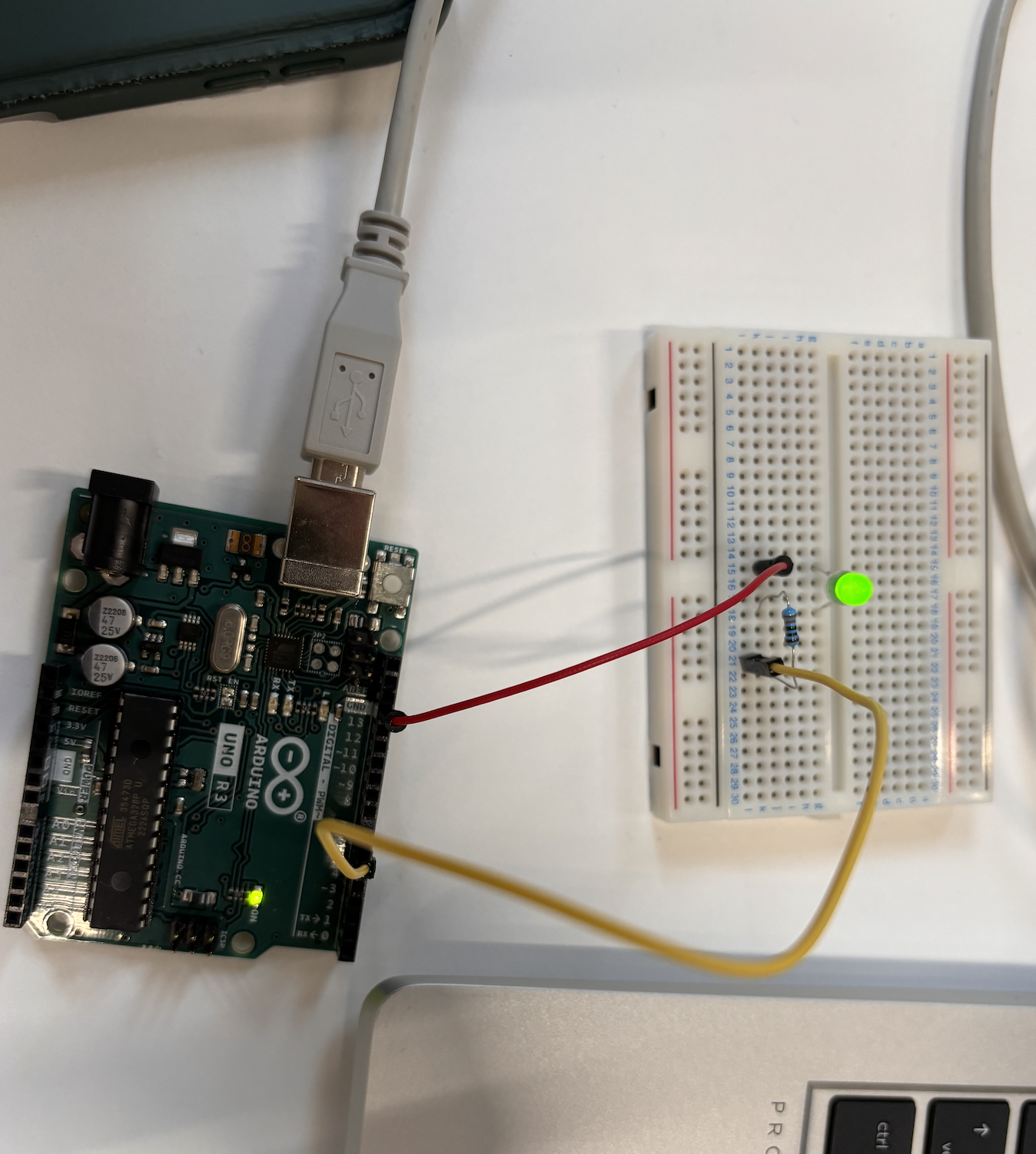
Application du code :

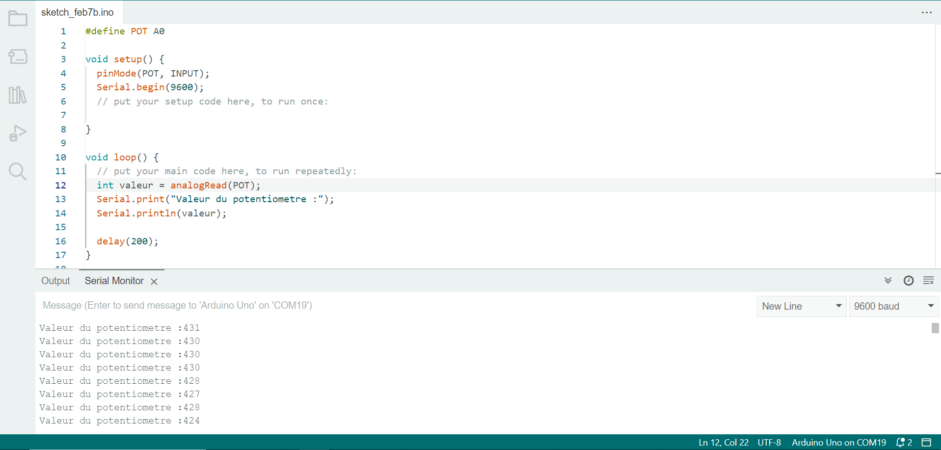
POTENTIOMETRE :
#define POT A0
void setup() {
pinMode(POT, INPUT);
Serial.begin(9600);
// put your setup code here, to run once:
}
void loop() {
// put your main code here, to run repeatedly:
int valeur = analogRead(POT);
Serial.print("Valeur du potentiometre :");
Serial.println(valeur);
delay(200);
}
Vérification du code:
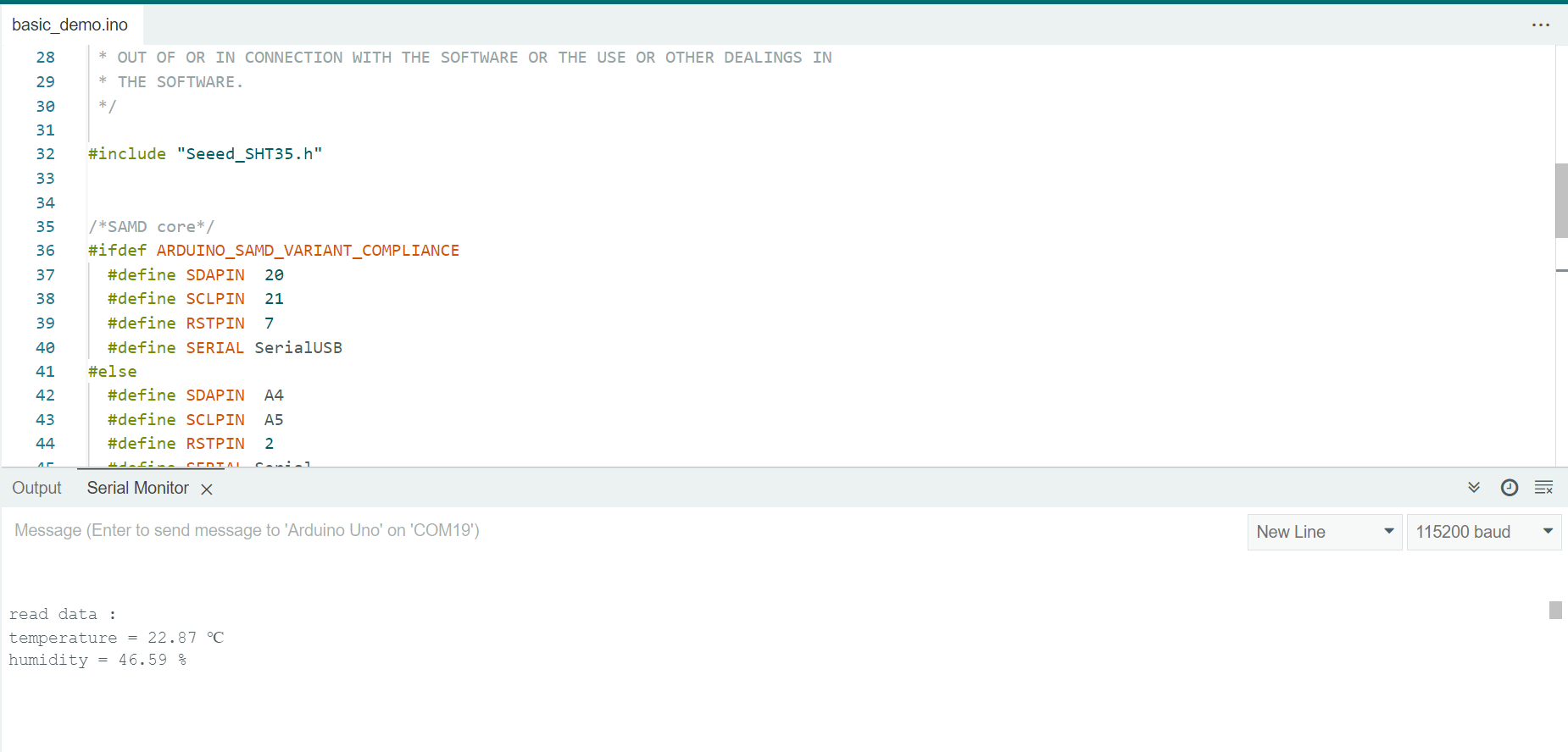
TEMPERATURE :
#include "Seeed_SHT35.h"
/*SAMD core*/
#ifdef ARDUINO_SAMD_VARIANT_COMPLIANCE
#define SDAPIN 20
#define SCLPIN 21
#define RSTPIN 7
#define SERIAL SerialUSB
#else
#define SDAPIN A4
#define SCLPIN A5
#define RSTPIN 2
#define SERIAL Serial
#endif
SHT35 sensor(SCLPIN);
void setup()
{
SERIAL.begin(115200);
delay(10);
SERIAL.println("serial start!!");
if(sensor.init())
{
SERIAL.println("sensor init failed!!!");
}
delay(1000);
}
void loop()
{
u16 value=0;
u8 data[6]={0};
float temp,hum;
if(NO_ERROR!=sensor.read_meas_data_single_shot(HIGH_REP_WITH_STRCH,&temp,&hum))
{
SERIAL.println("read temp failed!!");
SERIAL.println(" ");
SERIAL.println(" ");
SERIAL.println(" ");
}
else
{
SERIAL.println("read data :");
SERIAL.print("temperature = ");
SERIAL.print(temp);
SERIAL.println(" ℃ ");
SERIAL.print("humidity = ");
SERIAL.print(hum);
SERIAL.println(" % ");
SERIAL.println(" ");
SERIAL.println(" ");
SERIAL.println(" ");
}
delay(1000);
}
APPLICATION DU CODE :
 LED S'ALLUME EN FONCTION DE LA TEMPERATURE :
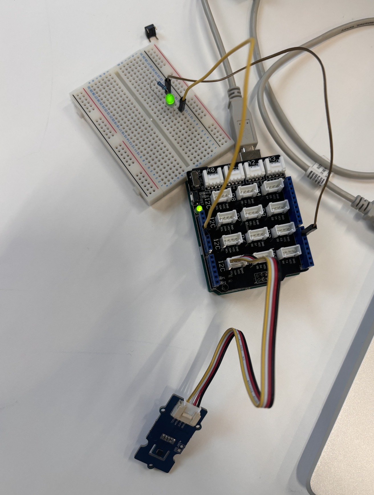
Image 2: Led s'allume avec la temperature
#include "Seeed_SHT35.h"
#define LED 6
/*SAMD core*/
#ifdef ARDUINO_SAMD_VARIANT_COMPLIANCE
#define SDAPIN 20
#define SCLPIN 21
#define RSTPIN 7
#define SERIAL SerialUSB
#else
#define SDAPIN A4
#define SCLPIN A5
#define RSTPIN 2
#define SERIAL Serial
#endif
SHT35 sensor(SCLPIN);
void setup()
{
SERIAL.begin(115200);
delay(10);
SERIAL.println("serial start!!");
if(sensor.init())
{
SERIAL.println("sensor init failed!!!");
}
delay(1000);
pinMode(LED, OUTPUT);
}
void loop()
{
u16 value=0;
u8 data[6]={0};
float temp,hum;
if(NO_ERROR!=sensor.read_meas_data_single_shot(HIGH_REP_WITH_STRCH,&temp,&hum))
{
SERIAL.println("read temp failed!!");
SERIAL.println(" ");
SERIAL.println(" ");
SERIAL.println(" ");
}
else
{
SERIAL.println("read data :");
SERIAL.print("temperature = ");
SERIAL.print(temp);
if (temp >25){
digitalWrite(LED, HIGH); // turn the LED on (HIGH is the voltage level)
delay(2000);
}
SERIAL.println(" ℃ ");
SERIAL.print("humidity = ");
SERIAL.print(hum);
SERIAL.println(" % ");
SERIAL.println(" ");
SERIAL.println(" ");
SERIAL.println(" ");
}
delay(1000);
}
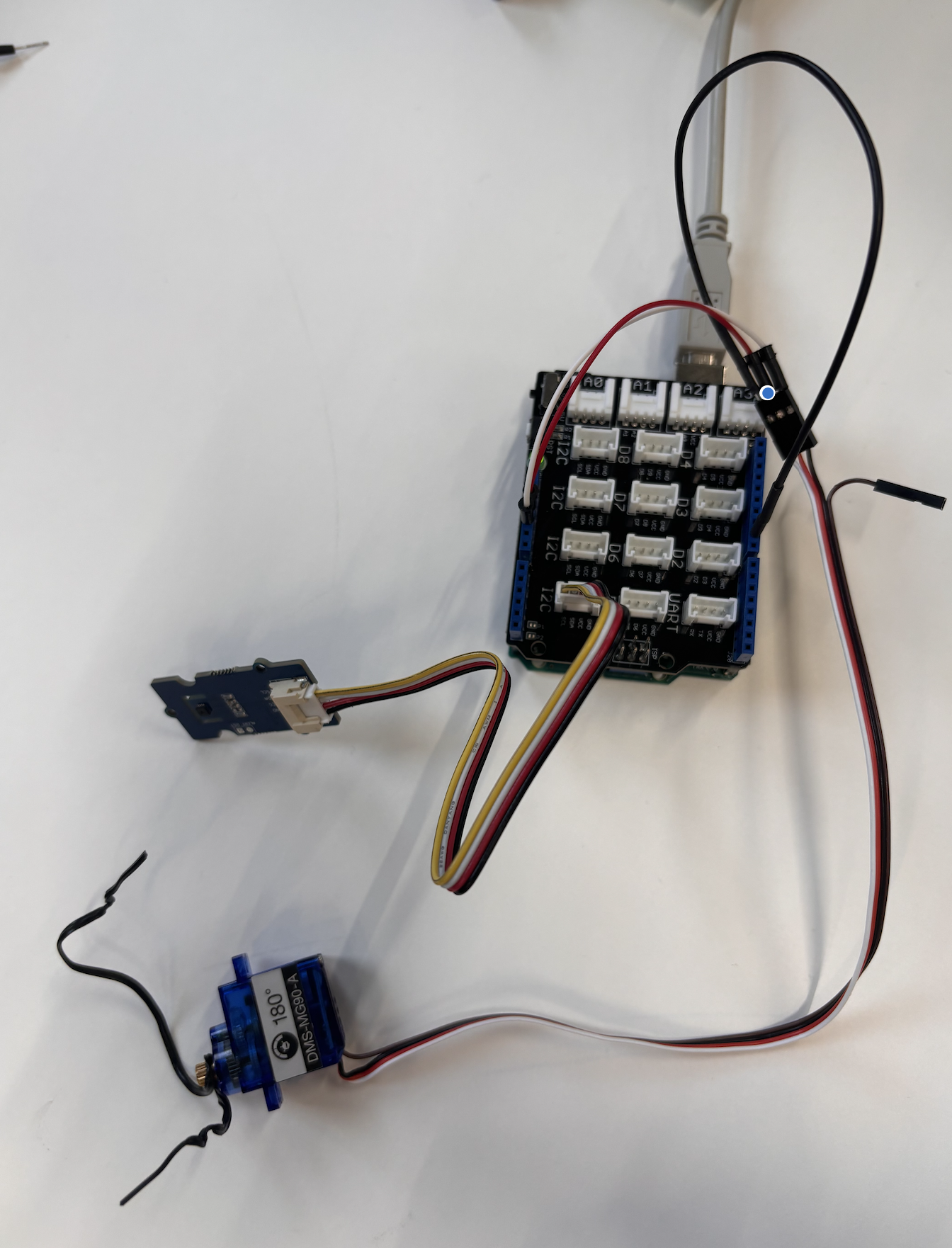
Image 3: Motor
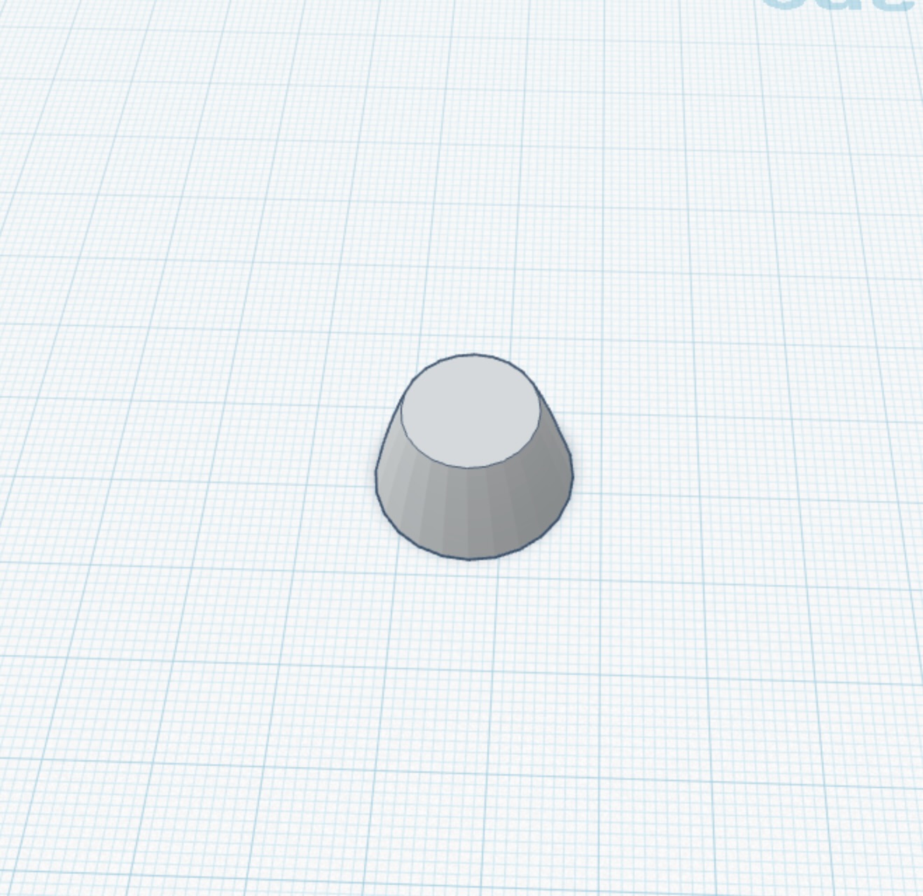
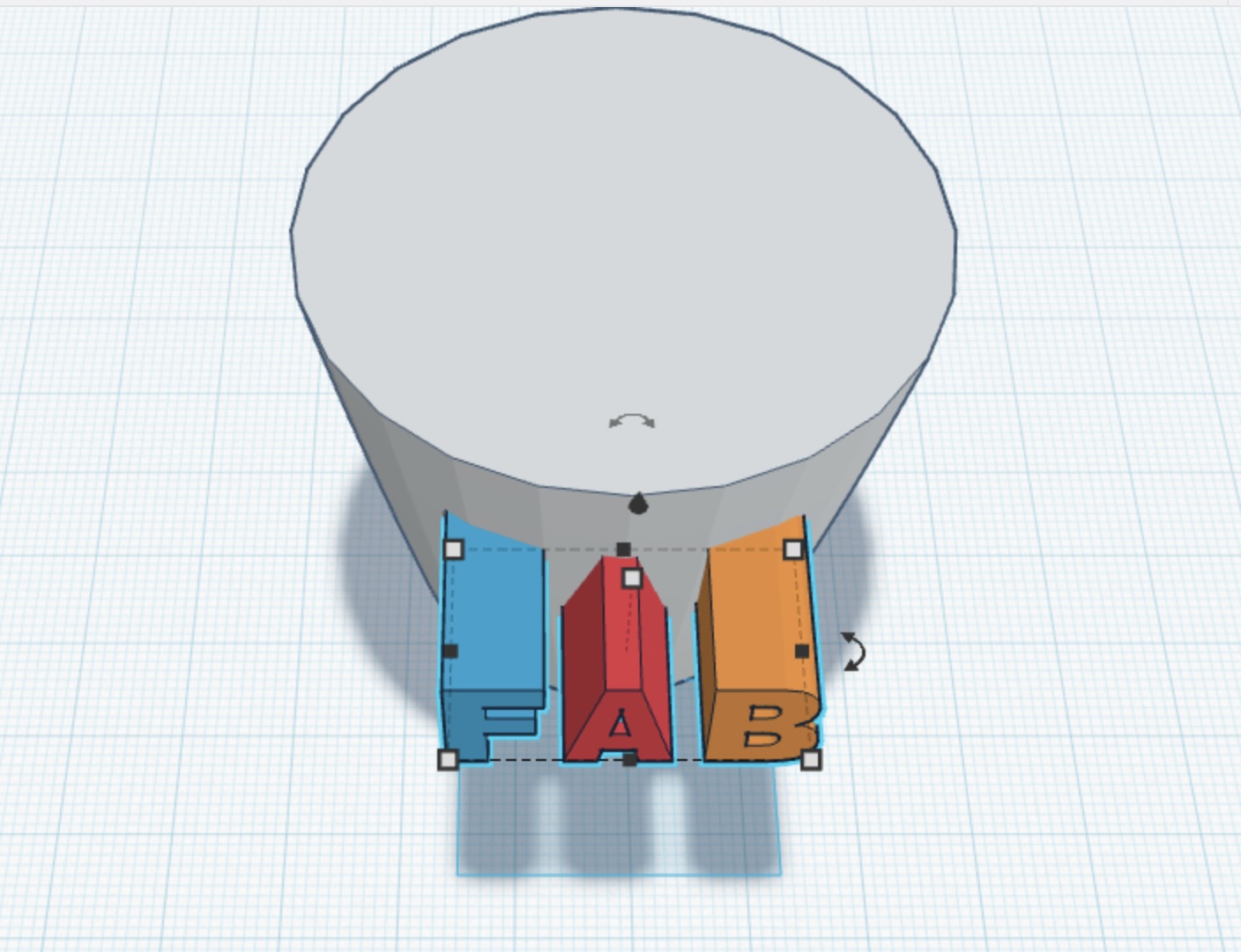
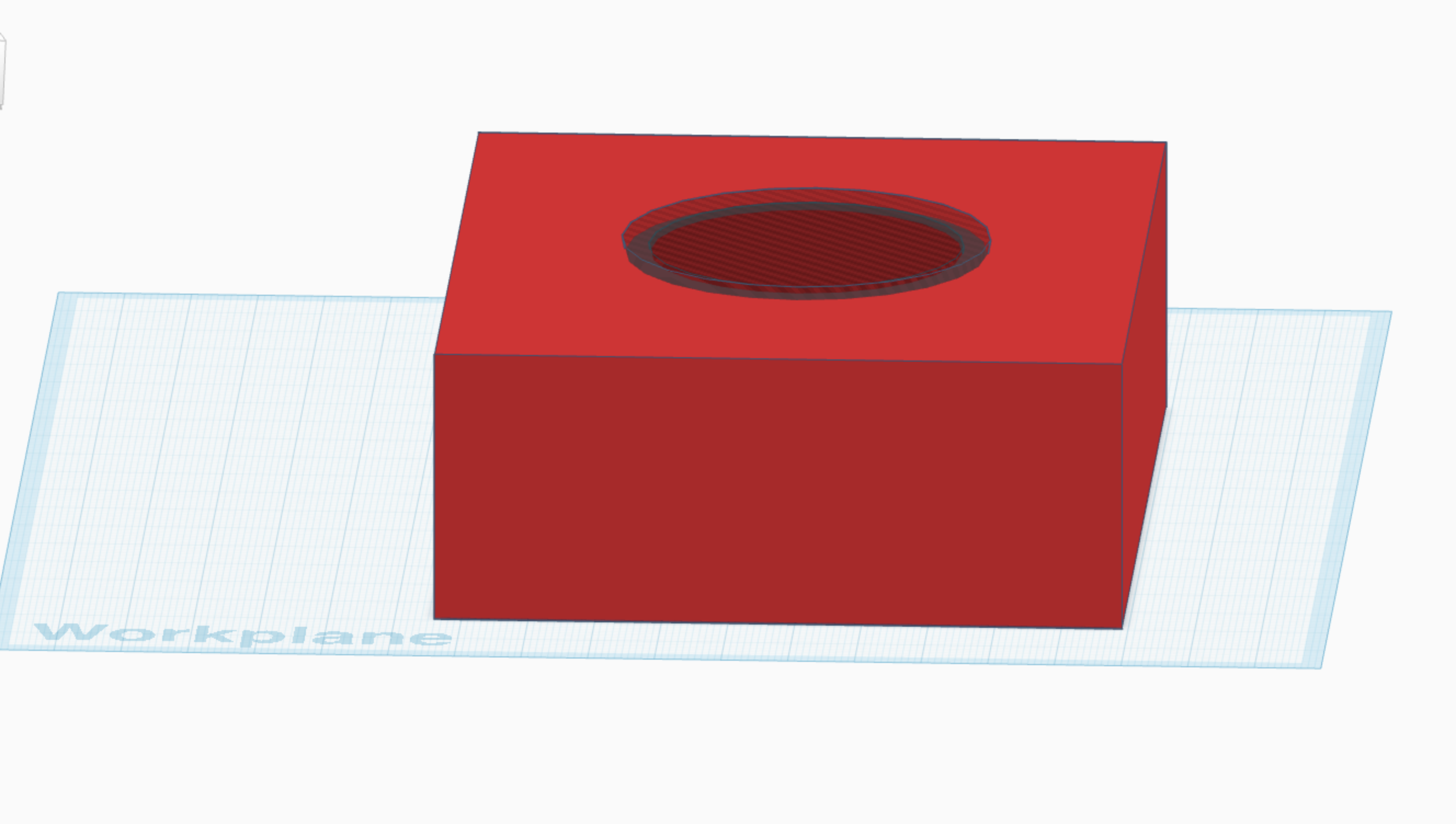
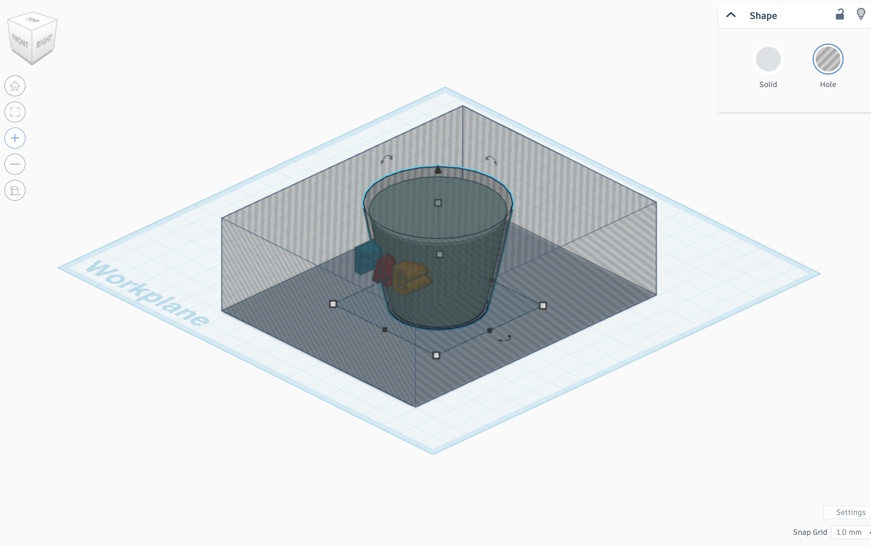
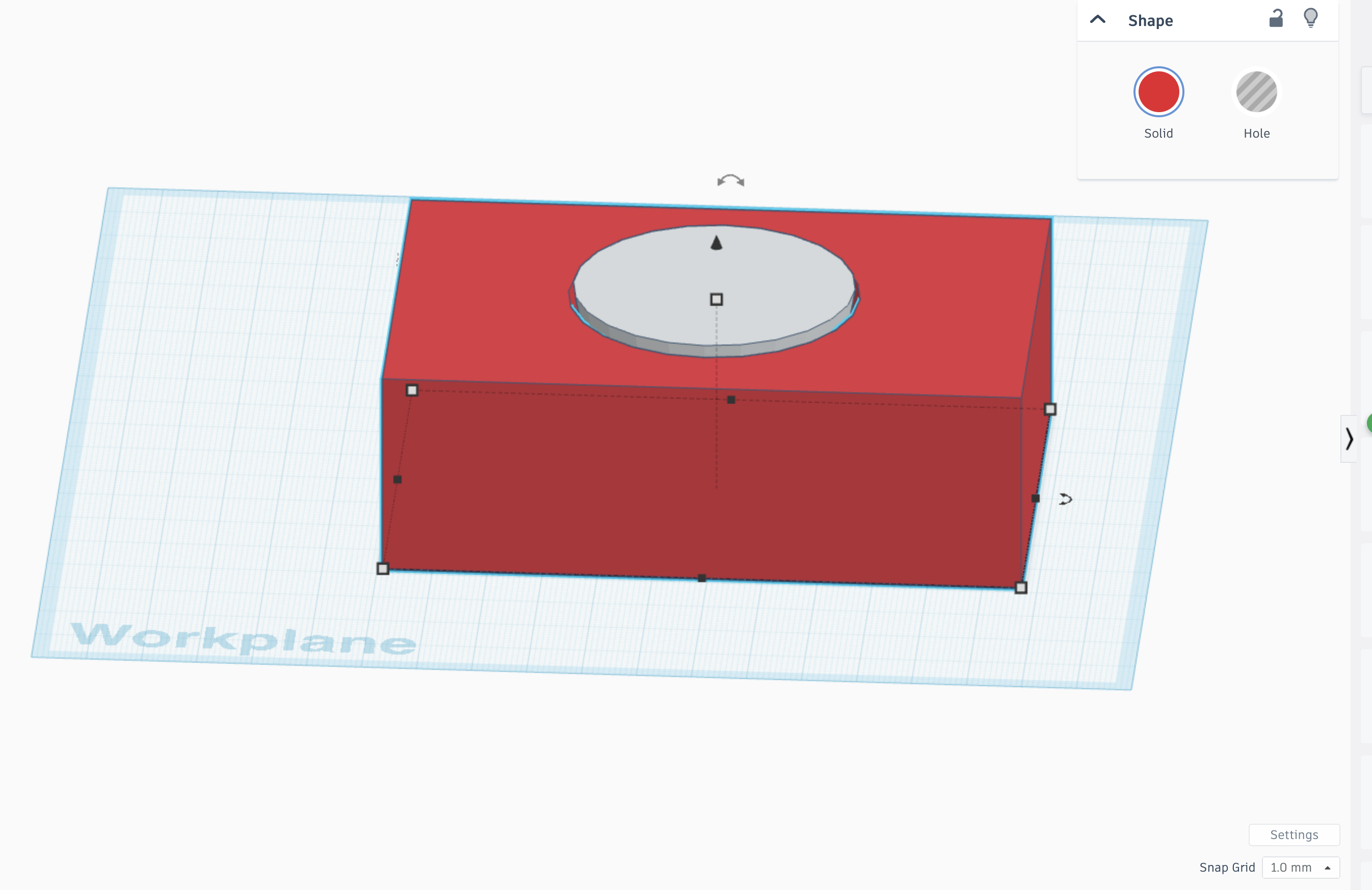
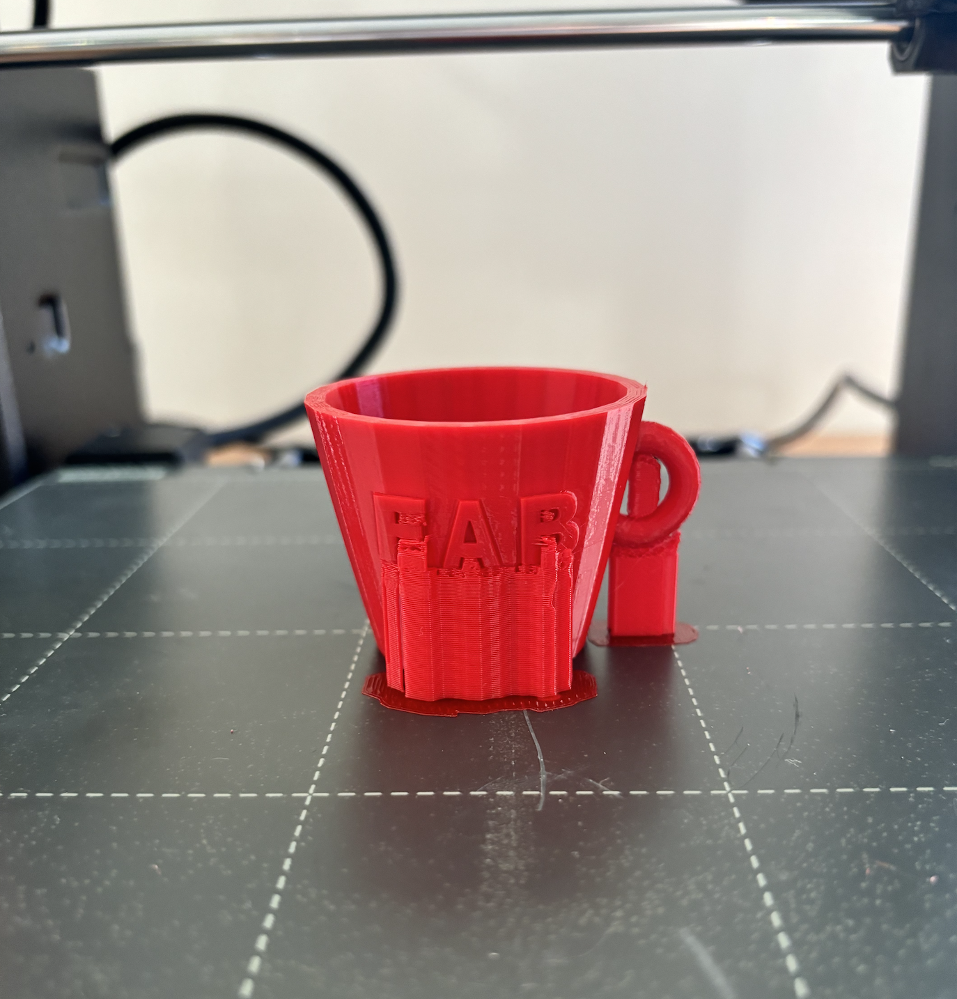
Impression 3D:
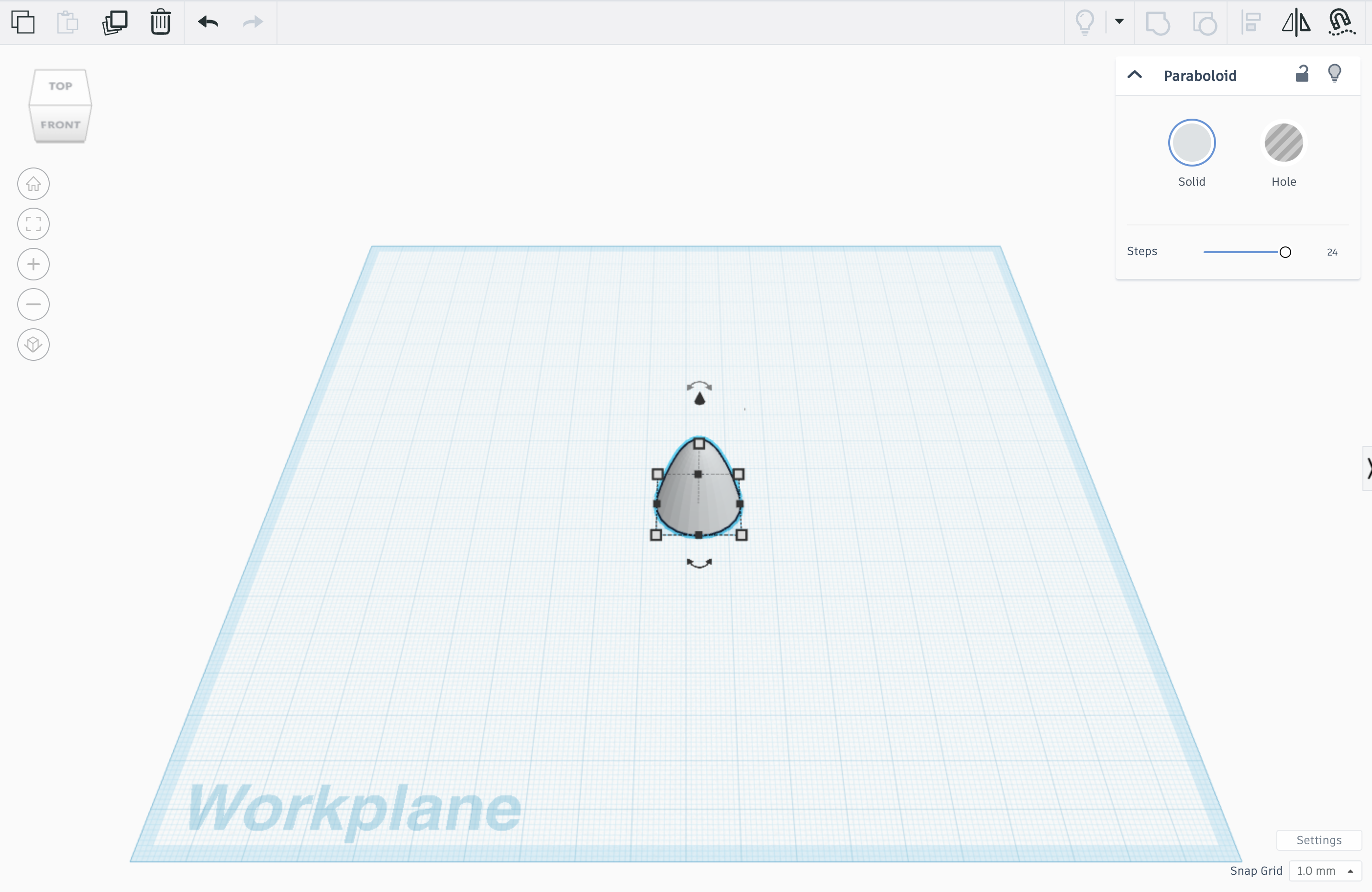
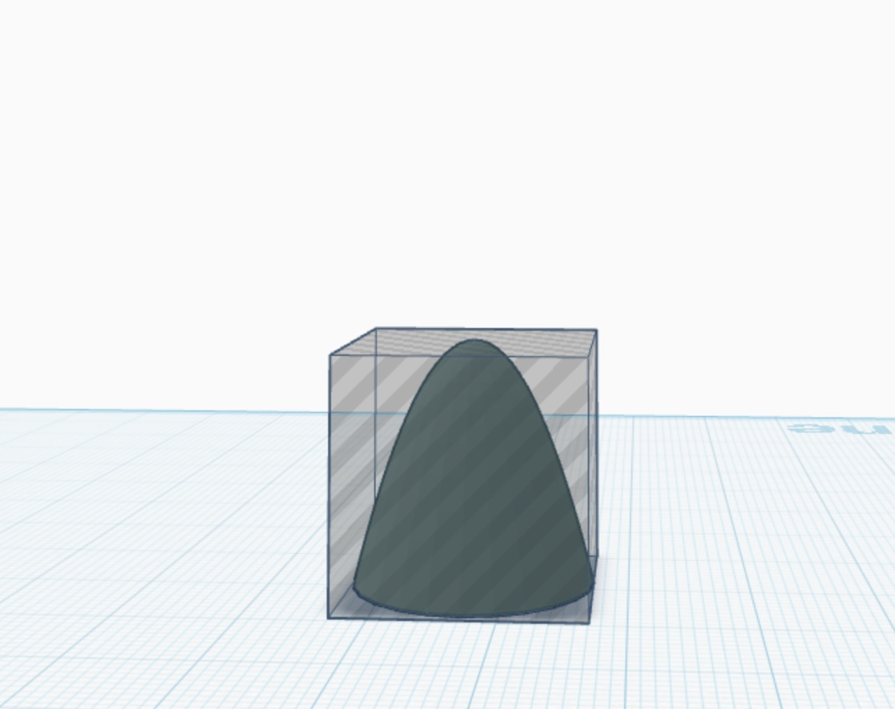
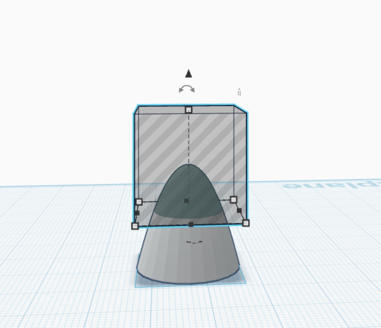
Le design était effectué sur TINKERCAD
ETAPE 1
ETAPE 2
ETAPE 3
ETAPE 4
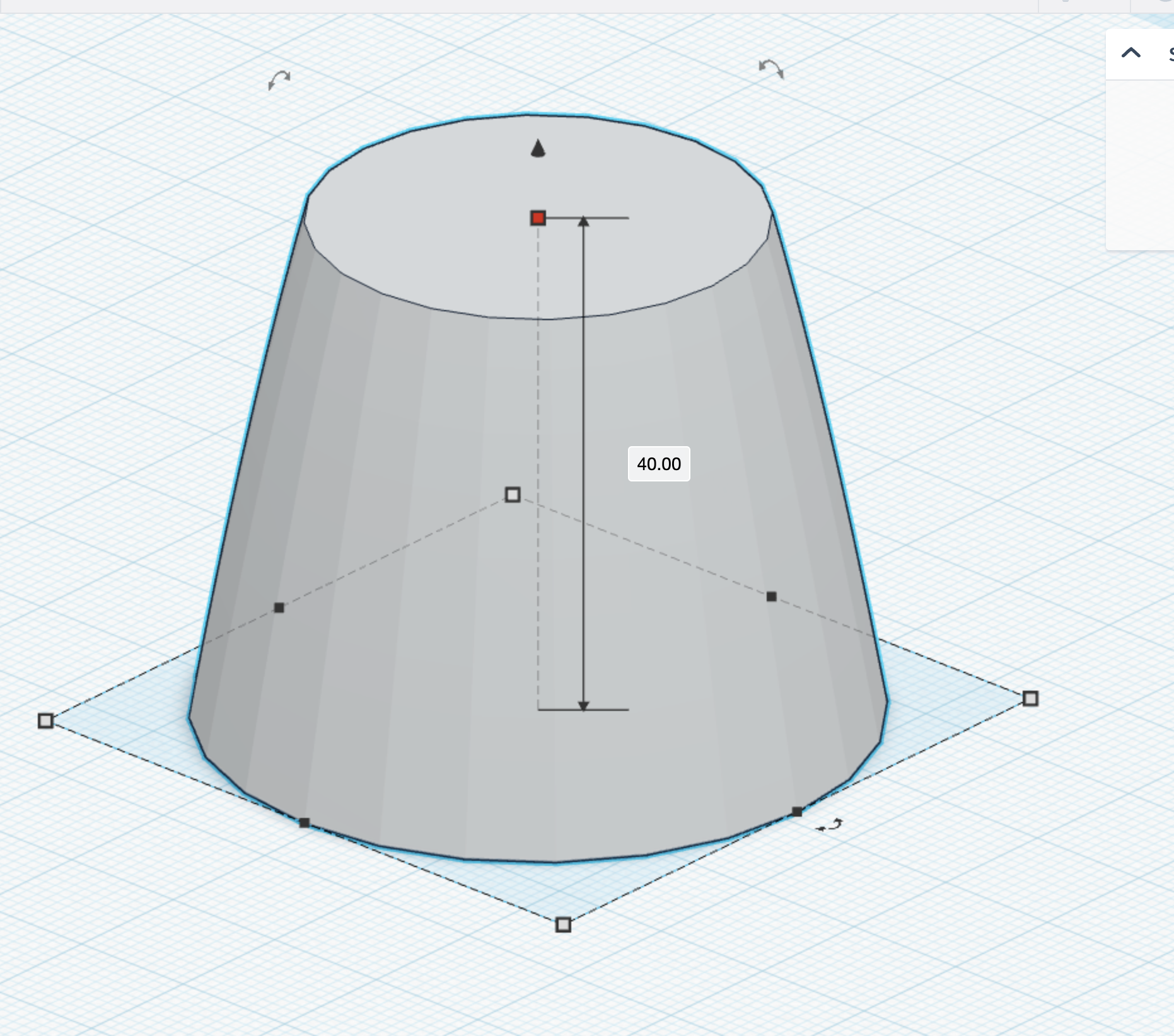
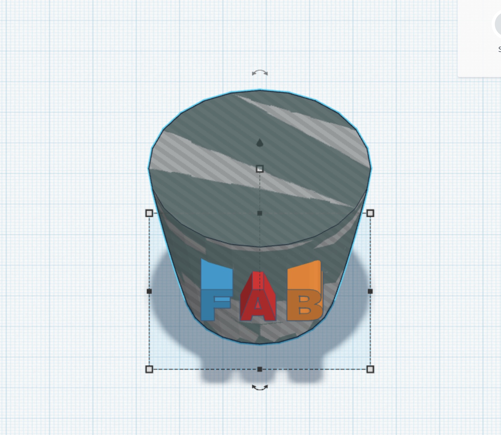
ETAPE 5
Height: 40
Diameter: 51
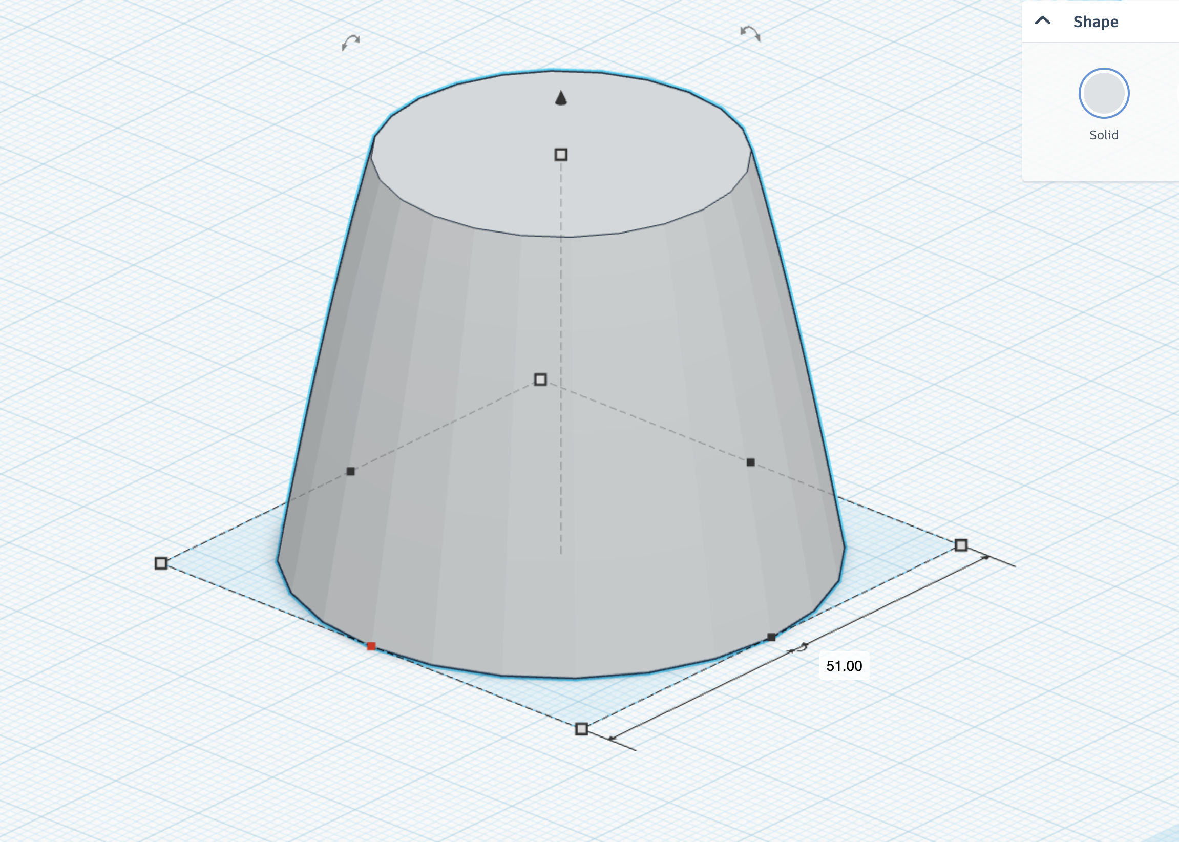
ETAPE 6:
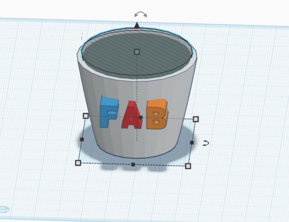
ETAPE 7

ETAPE 8

ETAPE 9
ETAPE 10
ETAPE 11
ETAPE 12
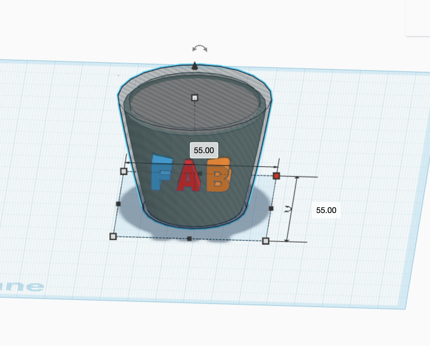
ETAPE 13

ETAPE 14
ETAPE 15
ETAPE 16
ETAPE 17

ETAPE 18

ETAPE 19

ETAPE 20
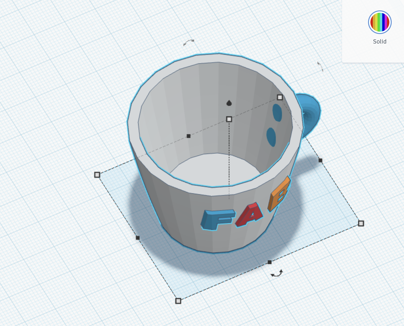
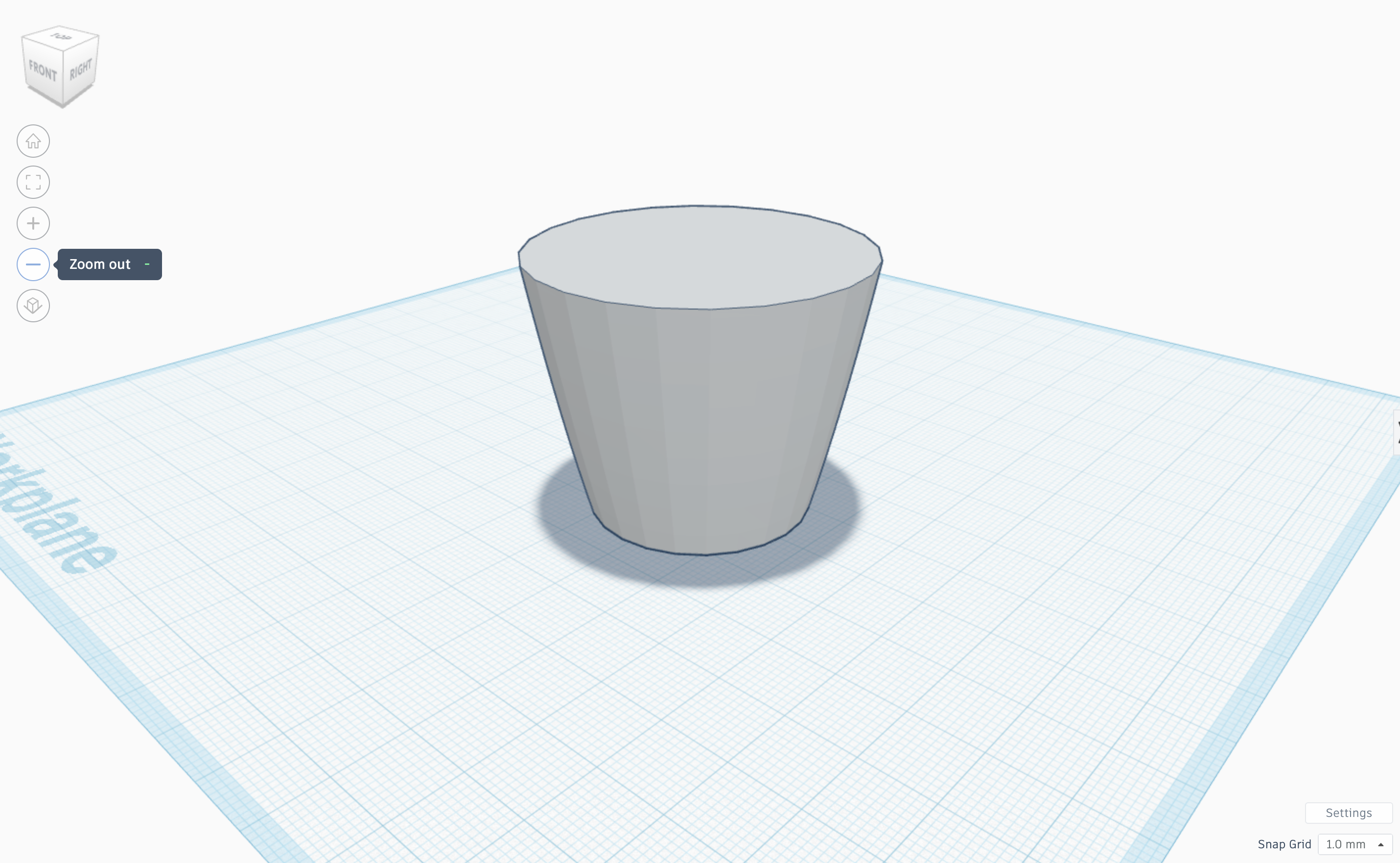
FINAL TINKERCAD VERSION:

EXPORT TO STL FORMAT:

FINAL 3D PRODUCT:

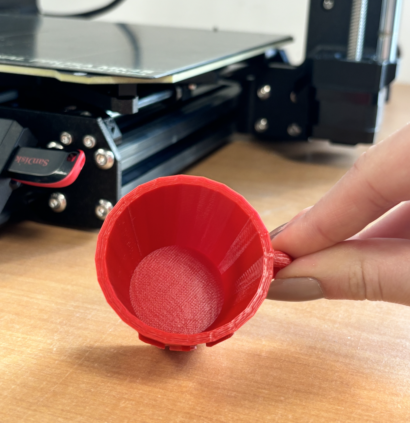


Projet Finale:
- Concevoir un système d’alerte de température qui détecte une chaleur excessive avec thermomètre , déclenche une alerte visuelle avec une LED et active un ventilateur pour refroidir l’environnement.
- Ce système peut être utilisé pour protéger des équipements électroniques, surveiller une pièce, ou éviter la surchauffe d’un boîtier.