Projets MEBARKIA, AMMACHE, EL HELOU, LUSINIER & GAL
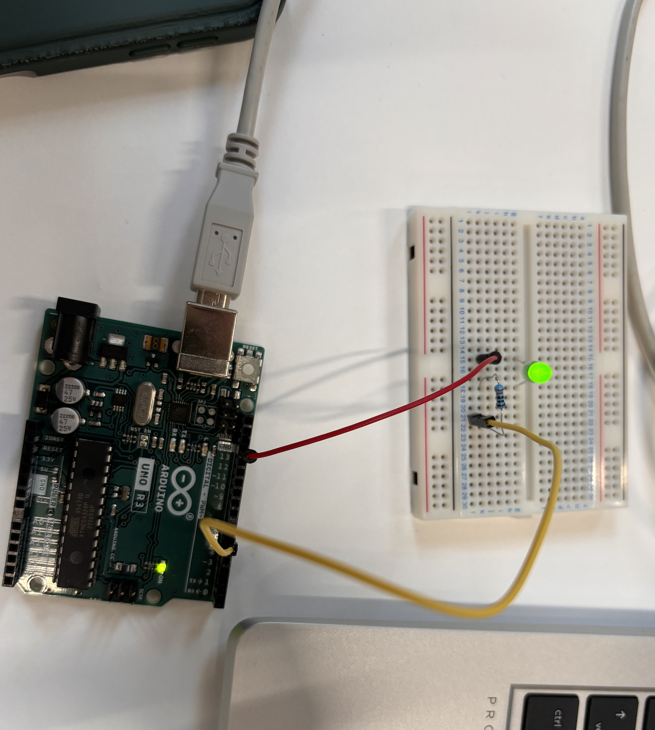
Allumage du LED :
#define LED 6
// the setup function runs once when you press reset or power the board
void setup() {
// initialize digital pin LED_BUILTIN as an output.
pinMode(LED, OUTPUT);
}
// the loop function runs over and over again forever
void loop() {
digitalWrite(LED, HIGH); // turn the LED on (HIGH is the voltage level)
delay(2000); // wait for a second
digitalWrite(LED, LOW); // turn the LED off by making the voltage LOW
delay(2000); // wait for a second
}
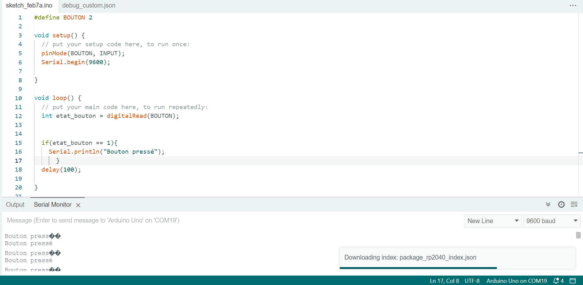
BOUTON PRESSE :
#define BOUTON 2
void setup() {
// put your setup code here, to run once:
pinMode(BOUTON, INPUT);
Serial.begin(9600);
}
void loop() {
// put your main code here, to run repeatedly:
int etat_bouton = digitalRead(BOUTON);
if(etat_bouton == 1){
Serial.println("Bouton pressé");
}
delay(100);
}
Application du code :
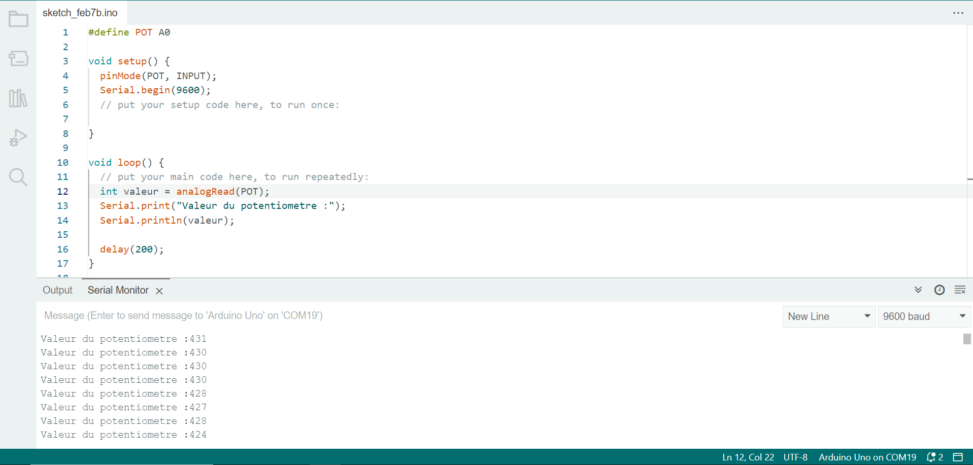
POTENTIOMETRE :
#define POT A0
void setup() {
pinMode(POT, INPUT);
Serial.begin(9600);
// put your setup code here, to run once:
}
void loop() {
// put your main code here, to run repeatedly:
int valeur = analogRead(POT);
Serial.print("Valeur du potentiometre :");
Serial.println(valeur);
delay(200);
}
Vérification du code:
TEMPERATURE :
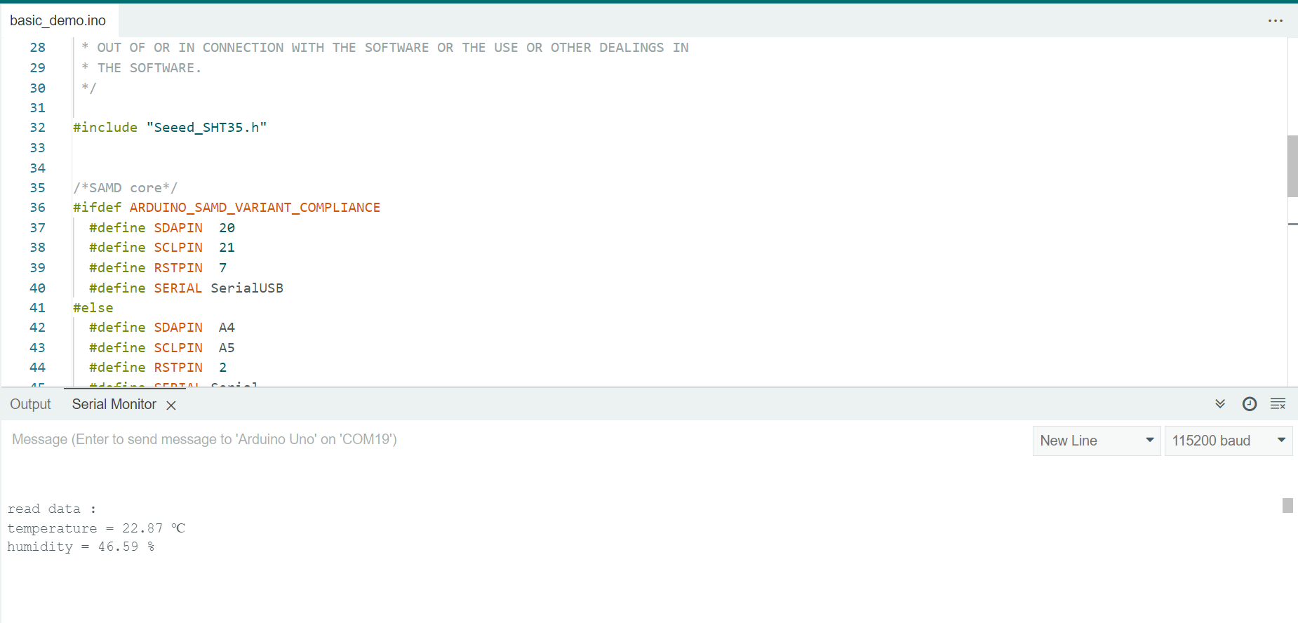
#include "Seeed_SHT35.h"
/*SAMD core*/
#ifdef ARDUINO_SAMD_VARIANT_COMPLIANCE
#define SDAPIN 20
#define SCLPIN 21
#define RSTPIN 7
#define SERIAL SerialUSB
#else
#define SDAPIN A4
#define SCLPIN A5
#define RSTPIN 2
#define SERIAL Serial
#endif
SHT35 sensor(SCLPIN);
void setup()
{
SERIAL.begin(115200);
delay(10);
SERIAL.println("serial start!!");
if(sensor.init())
{
SERIAL.println("sensor init failed!!!");
}
delay(1000);
}
void loop()
{
u16 value=0;
u8 data[6]={0};
float temp,hum;
if(NO_ERROR!=sensor.read_meas_data_single_shot(HIGH_REP_WITH_STRCH,&temp,&hum))
{
SERIAL.println("read temp failed!!");
SERIAL.println(" ");
SERIAL.println(" ");
SERIAL.println(" ");
}
else
{
SERIAL.println("read data :");
SERIAL.print("temperature = ");
SERIAL.print(temp);
SERIAL.println(" ℃ ");
SERIAL.print("humidity = ");
SERIAL.print(hum);
SERIAL.println(" % ");
SERIAL.println(" ");
SERIAL.println(" ");
SERIAL.println(" ");
}
delay(1000);
}
APPLICATION DU CODE :
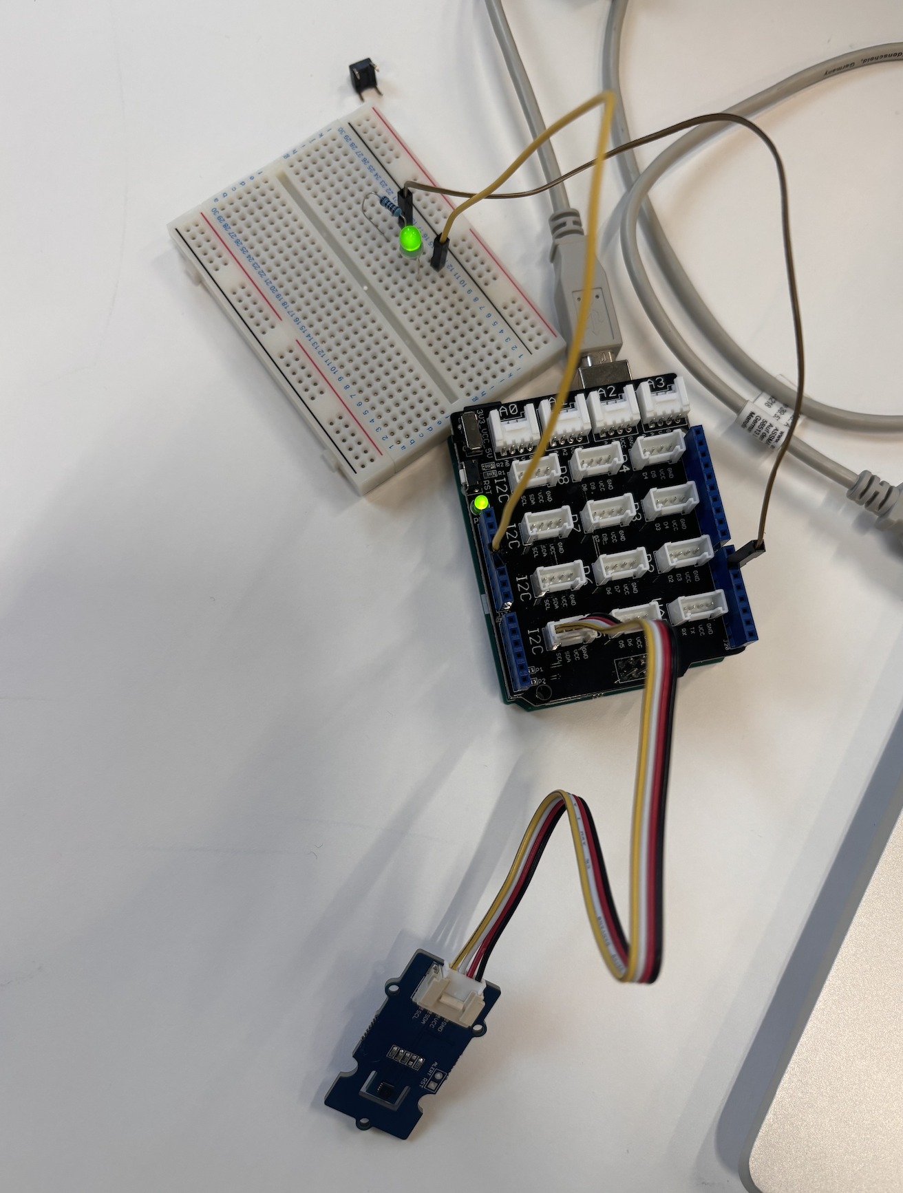
 LED S'ALLUME EN FONCTION DE LA TEMPERATURE :

Image 2: Led s'allume avec la temperature
#include "Seeed_SHT35.h"
#define LED 6
/*SAMD core*/
#ifdef ARDUINO_SAMD_VARIANT_COMPLIANCE
#define SDAPIN 20
#define SCLPIN 21
#define RSTPIN 7
#define SERIAL SerialUSB
#else
#define SDAPIN A4
#define SCLPIN A5
#define RSTPIN 2
#define SERIAL Serial
#endif
SHT35 sensor(SCLPIN);
void setup()
{
SERIAL.begin(115200);
delay(10);
SERIAL.println("serial start!!");
if(sensor.init())
{
SERIAL.println("sensor init failed!!!");
}
delay(1000);
pinMode(LED, OUTPUT);
}
void loop()
{
u16 value=0;
u8 data[6]={0};
float temp,hum;
if(NO_ERROR!=sensor.read_meas_data_single_shot(HIGH_REP_WITH_STRCH,&temp,&hum))
{
SERIAL.println("read temp failed!!");
SERIAL.println(" ");
SERIAL.println(" ");
SERIAL.println(" ");
}
else
{
SERIAL.println("read data :");
SERIAL.print("temperature = ");
SERIAL.print(temp);
if (temp >25){
digitalWrite(LED, HIGH); // turn the LED on (HIGH is the voltage level)
delay(2000);
}
SERIAL.println(" ℃ ");
SERIAL.print("humidity = ");
SERIAL.print(hum);
SERIAL.println(" % ");
SERIAL.println(" ");
SERIAL.println(" ");
SERIAL.println(" ");
}
delay(1000);
}

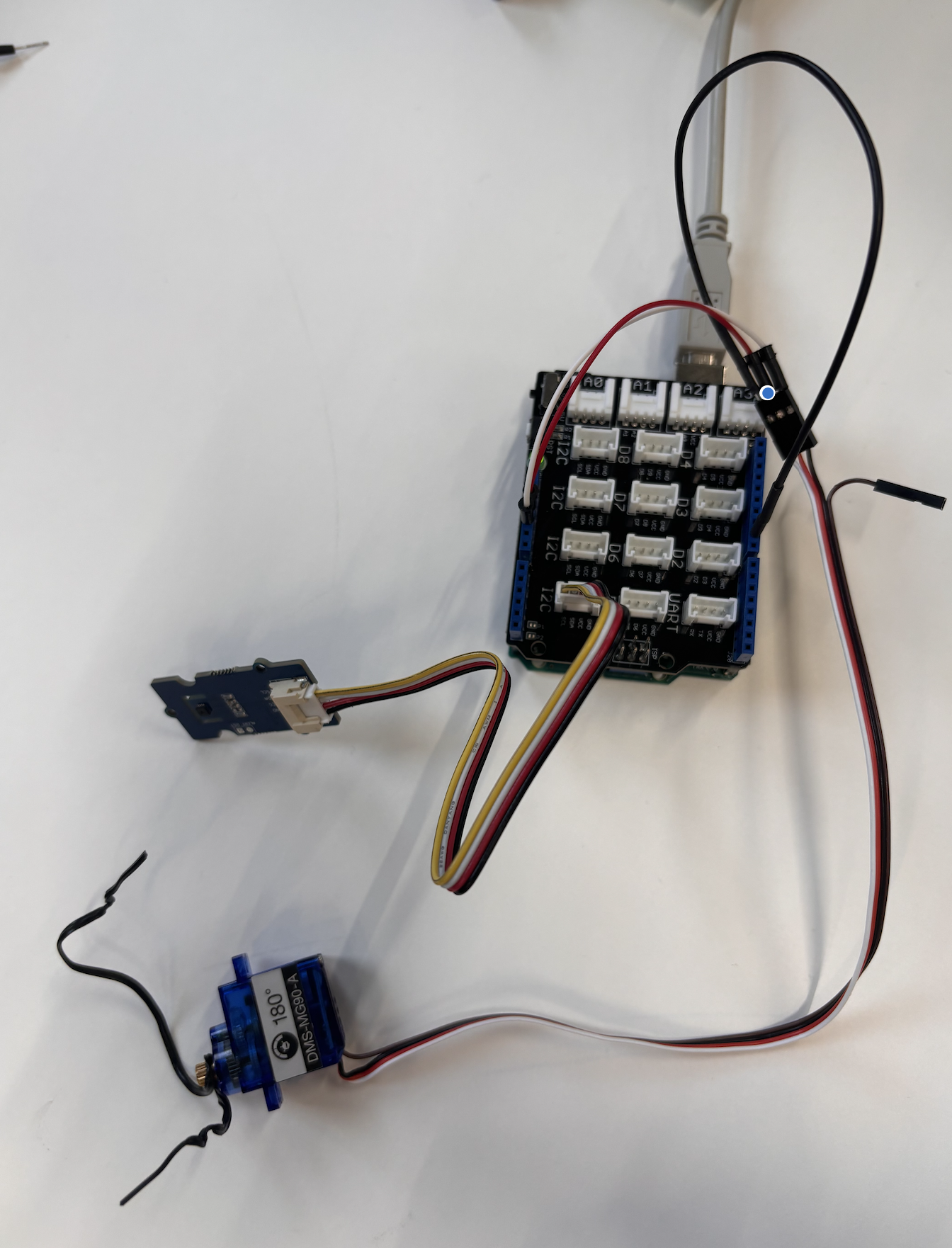
Image 3: Motor
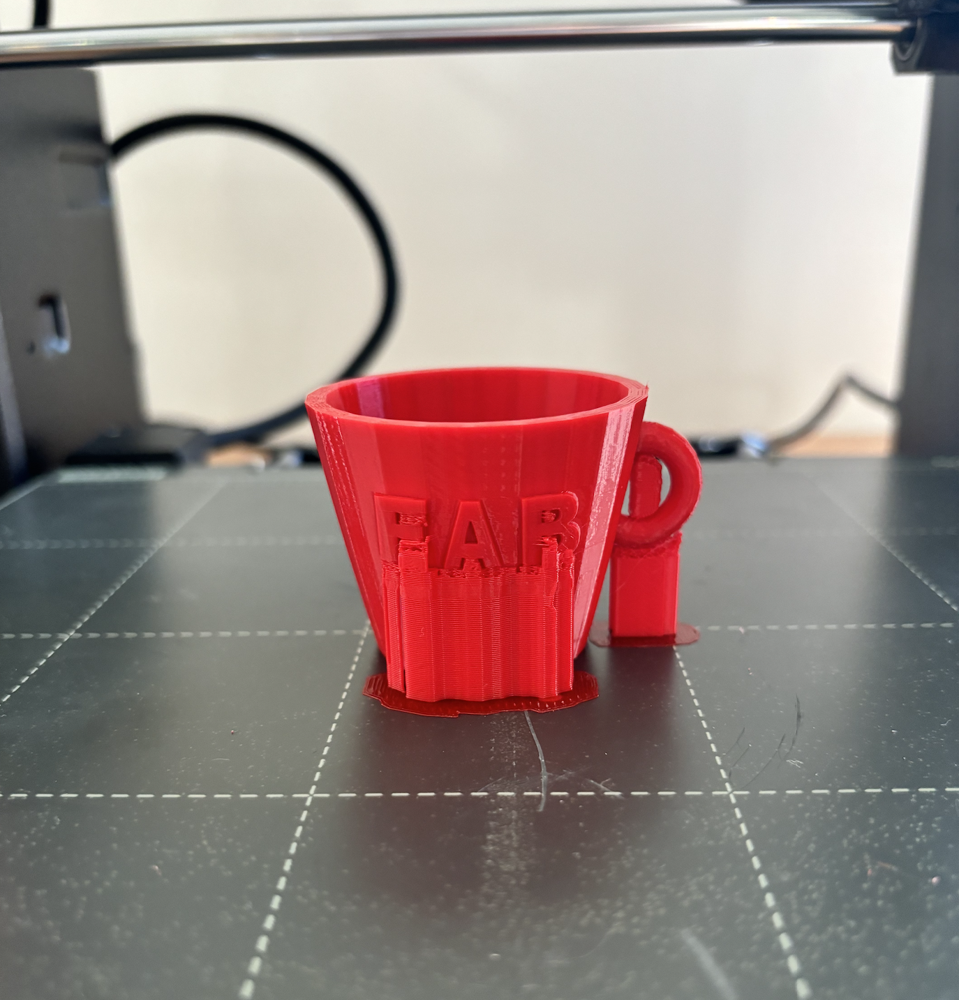
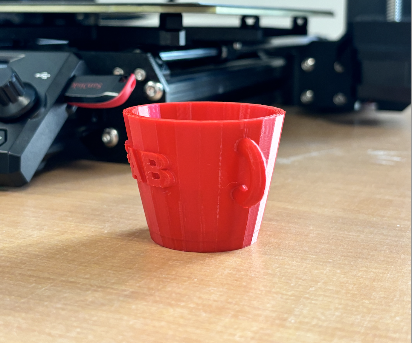
Impression 3D:
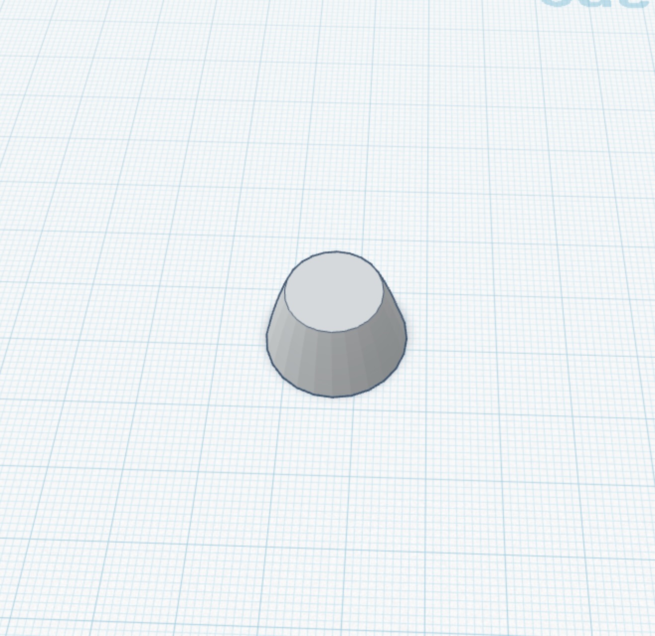
Le design était effectué sur TINKERCAD
ETAPE 1
ETAPE 2
ETAPE 3
ETAPE 4

ETAPE 5
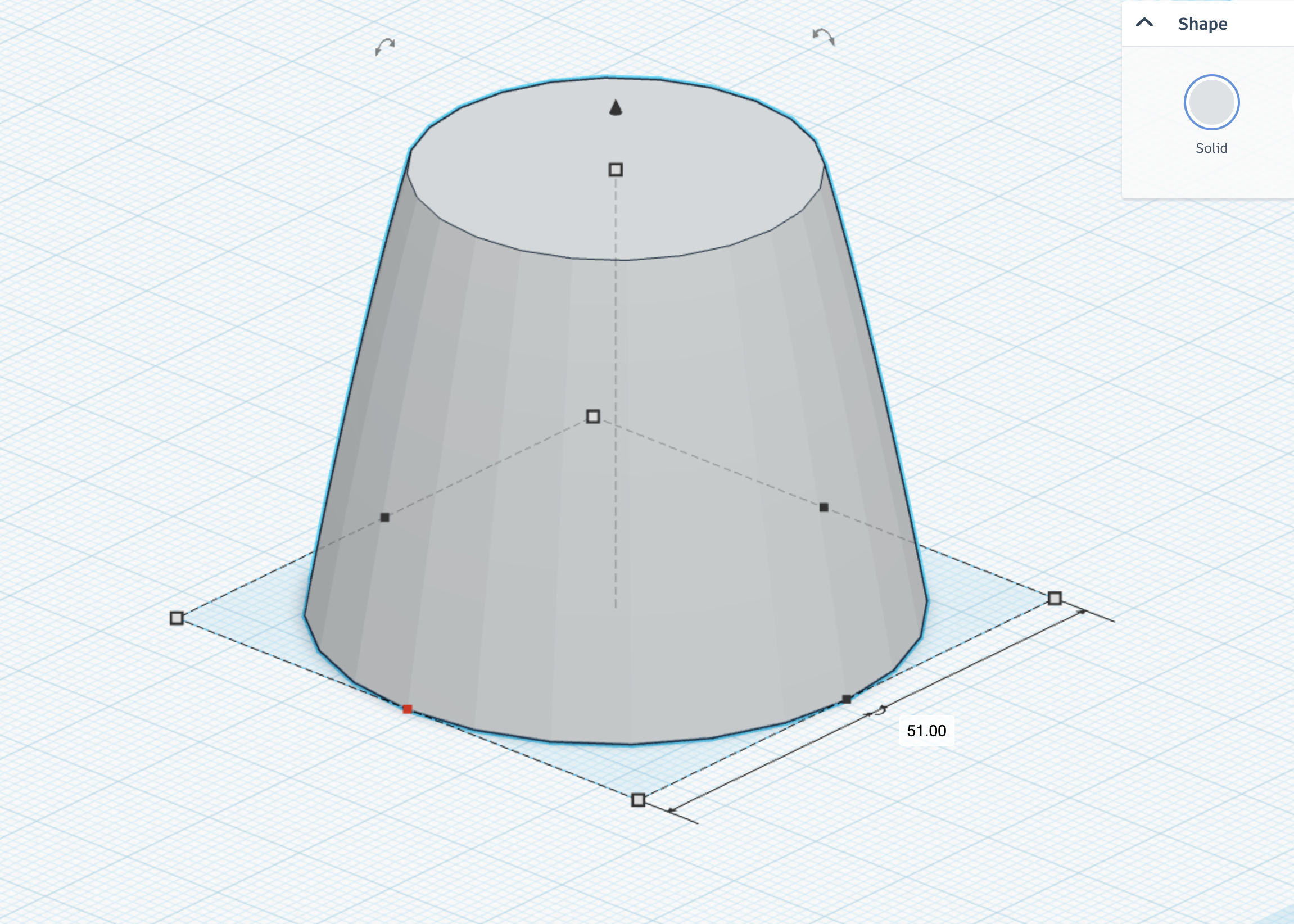
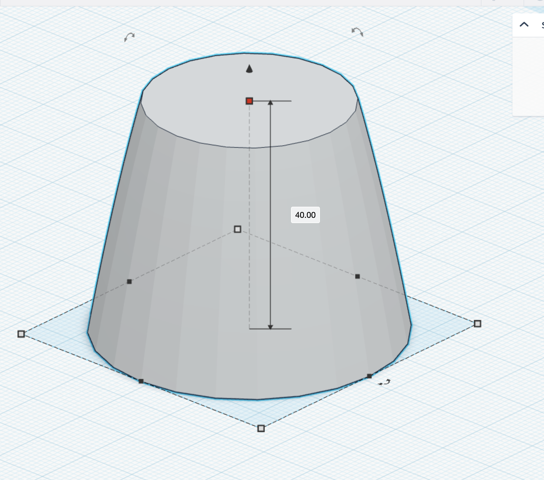
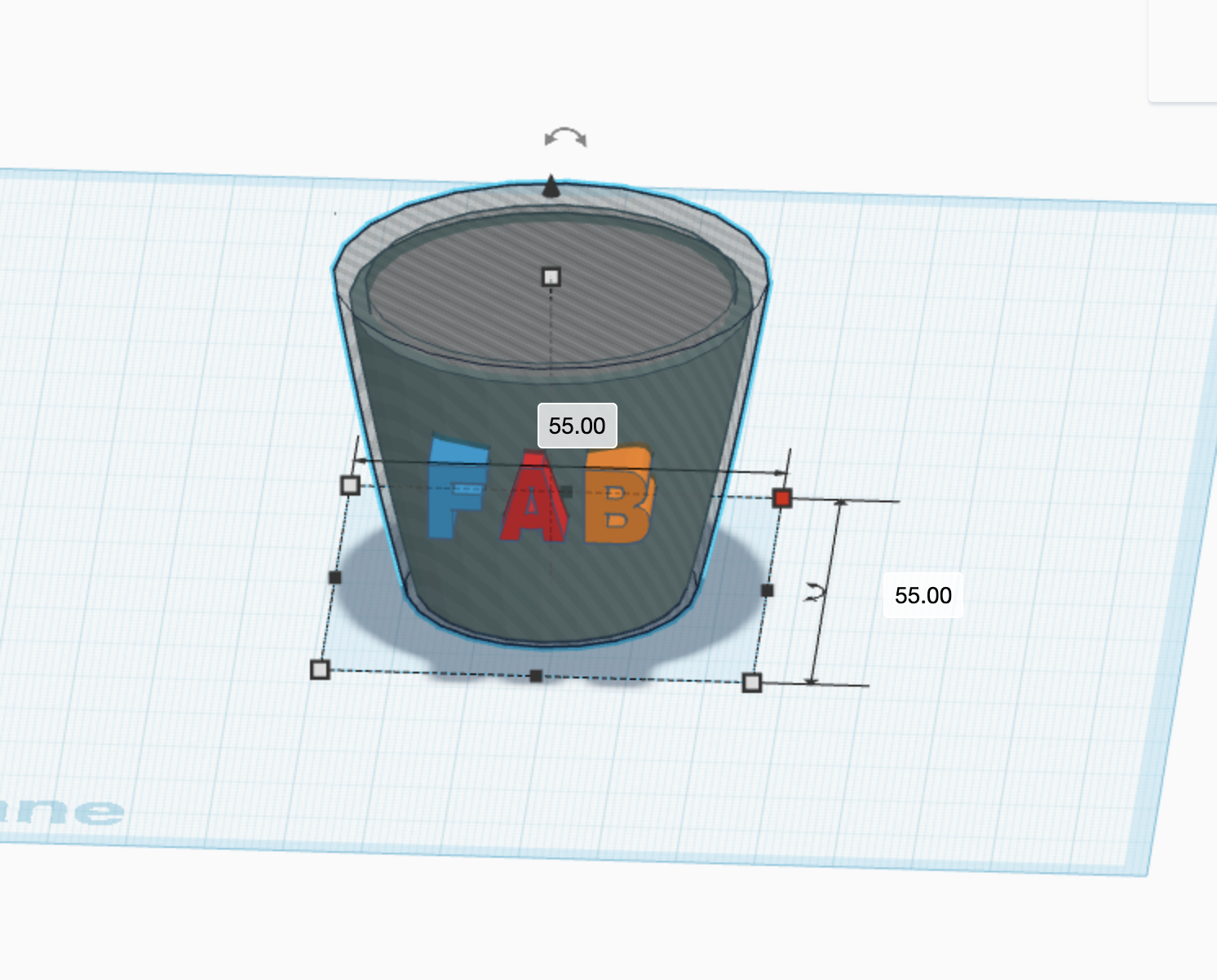
Height: 40
Diameter: 51


ETAPE 6:
ETAPE 7
ETAPE 8

ETAPE 9
ETAPE 10

ETAPE 11
ETAPE 12

ETAPE 13
ETAPE 14
ETAPE 15
ETAPE 16

ETAPE 17

ETAPE 18

ETAPE 19

ETAPE 20
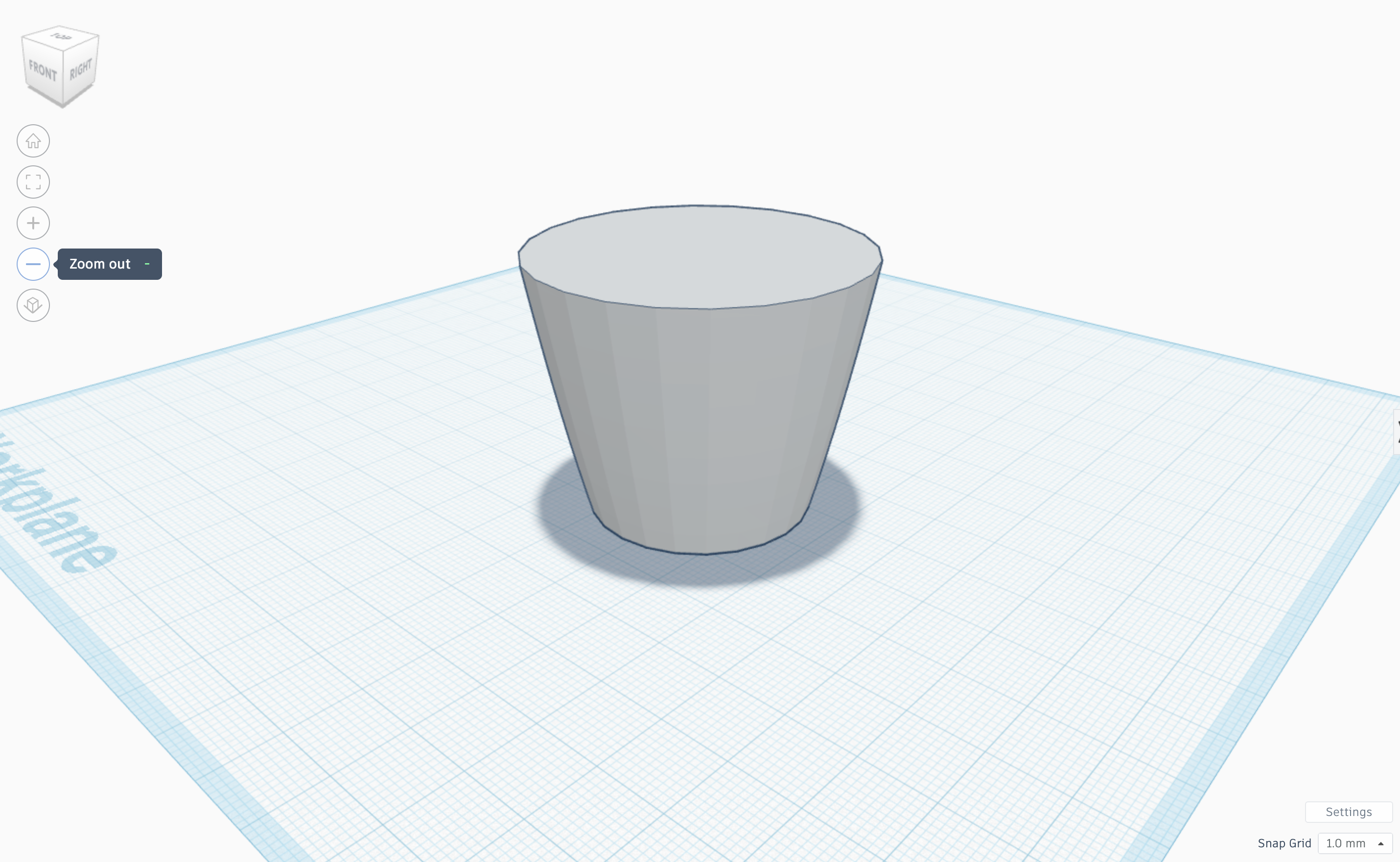
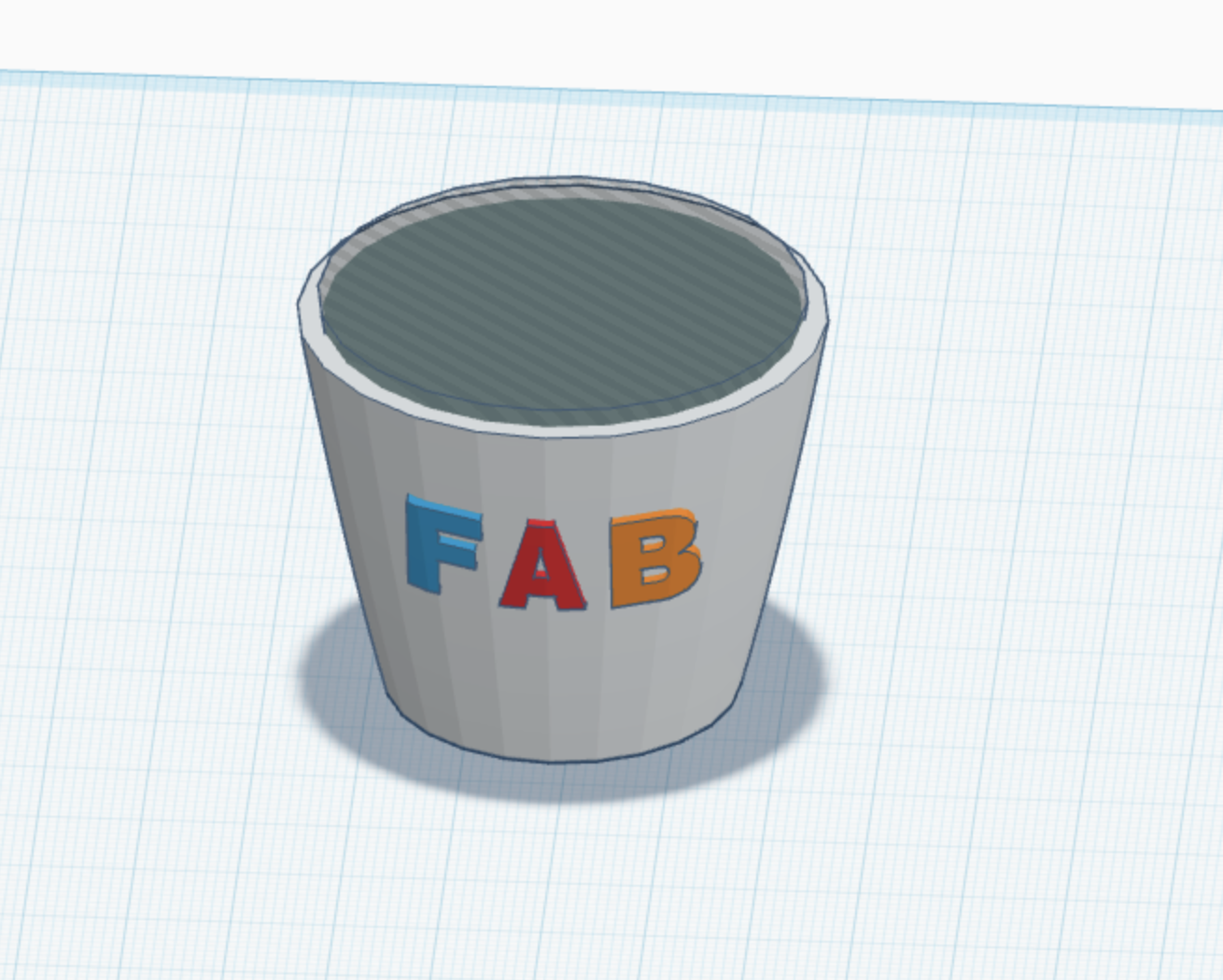
FINAL TINKERCAD VERSION:


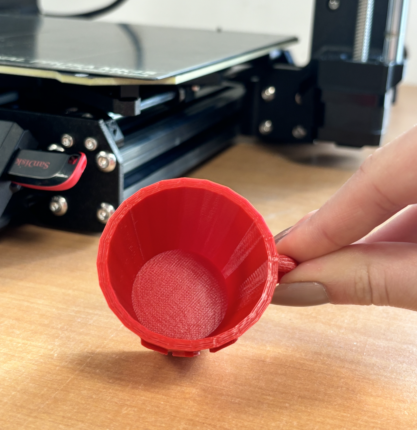
FINAL 3D PRODUCT:


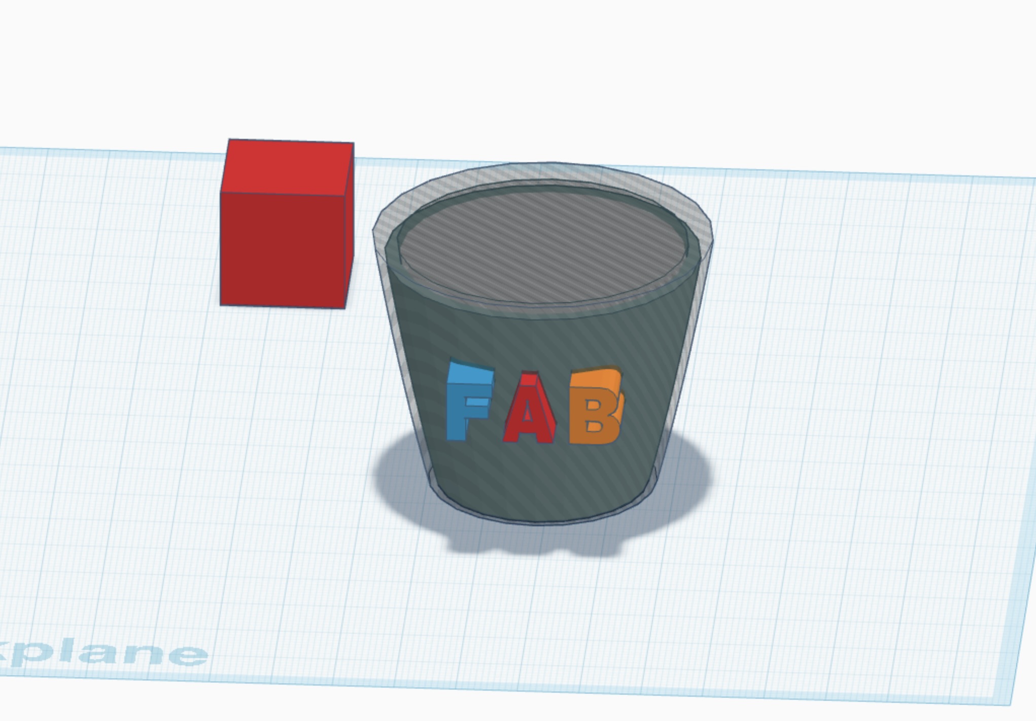
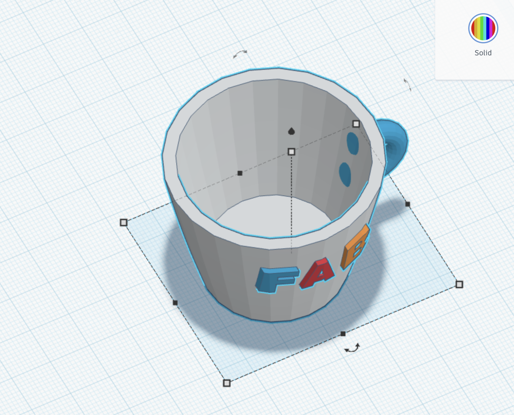
Conception d'un Espresso Cup sur Tinkercad
1. Création de la Forme de Base
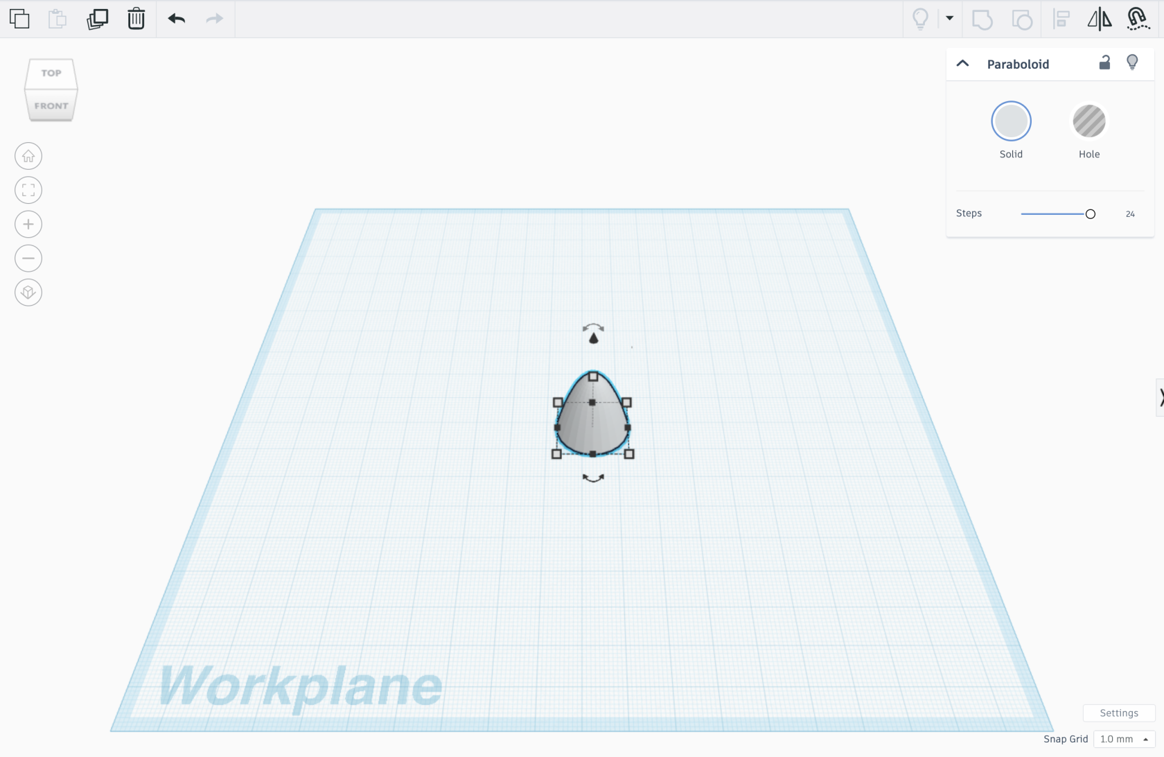
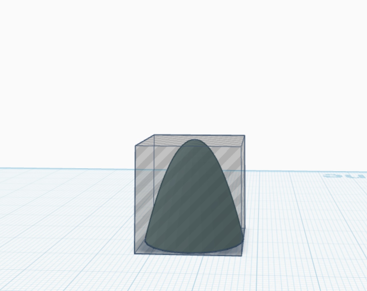
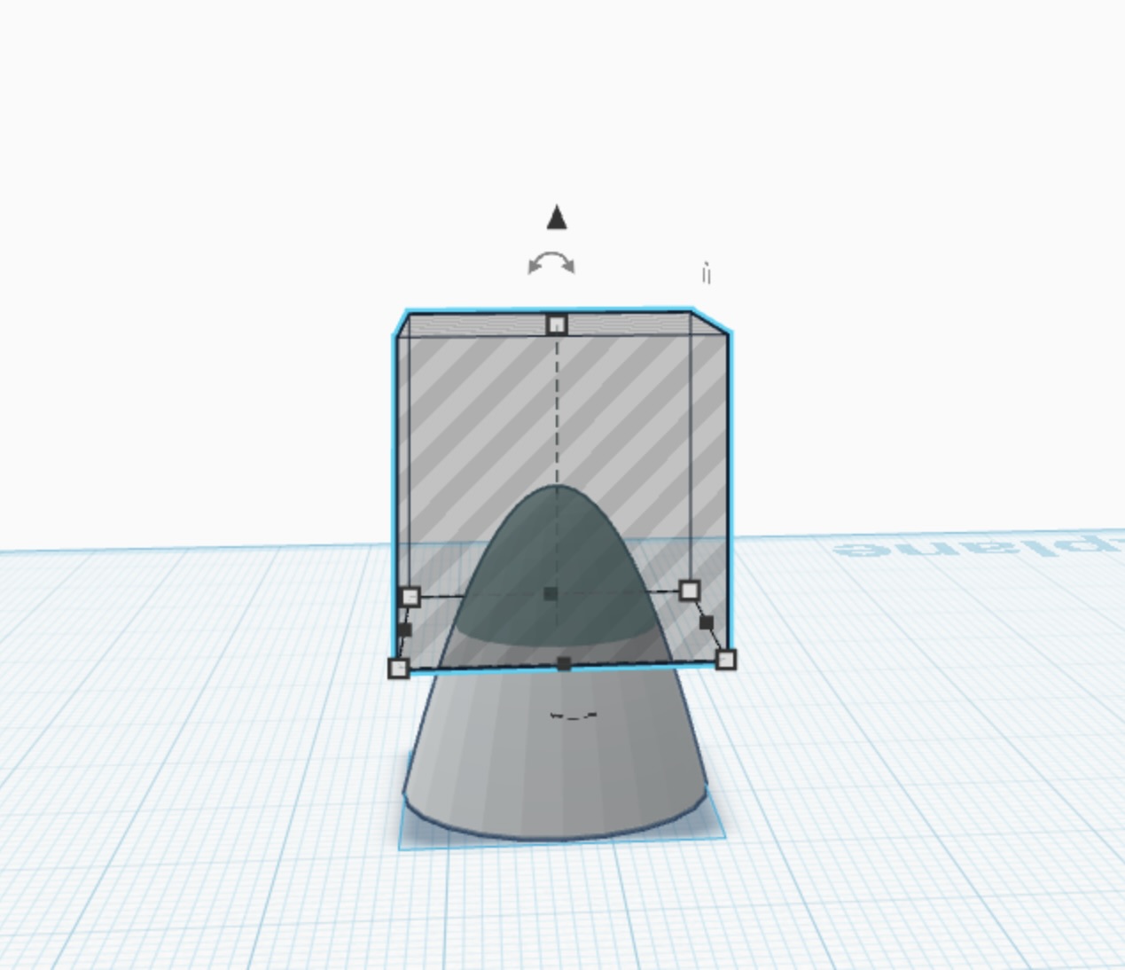
Nous avons commencé par utiliser une forme paraboloïde, disponible dans les formes géométriques de Tinkercad, pour définir la structure principale du cup.
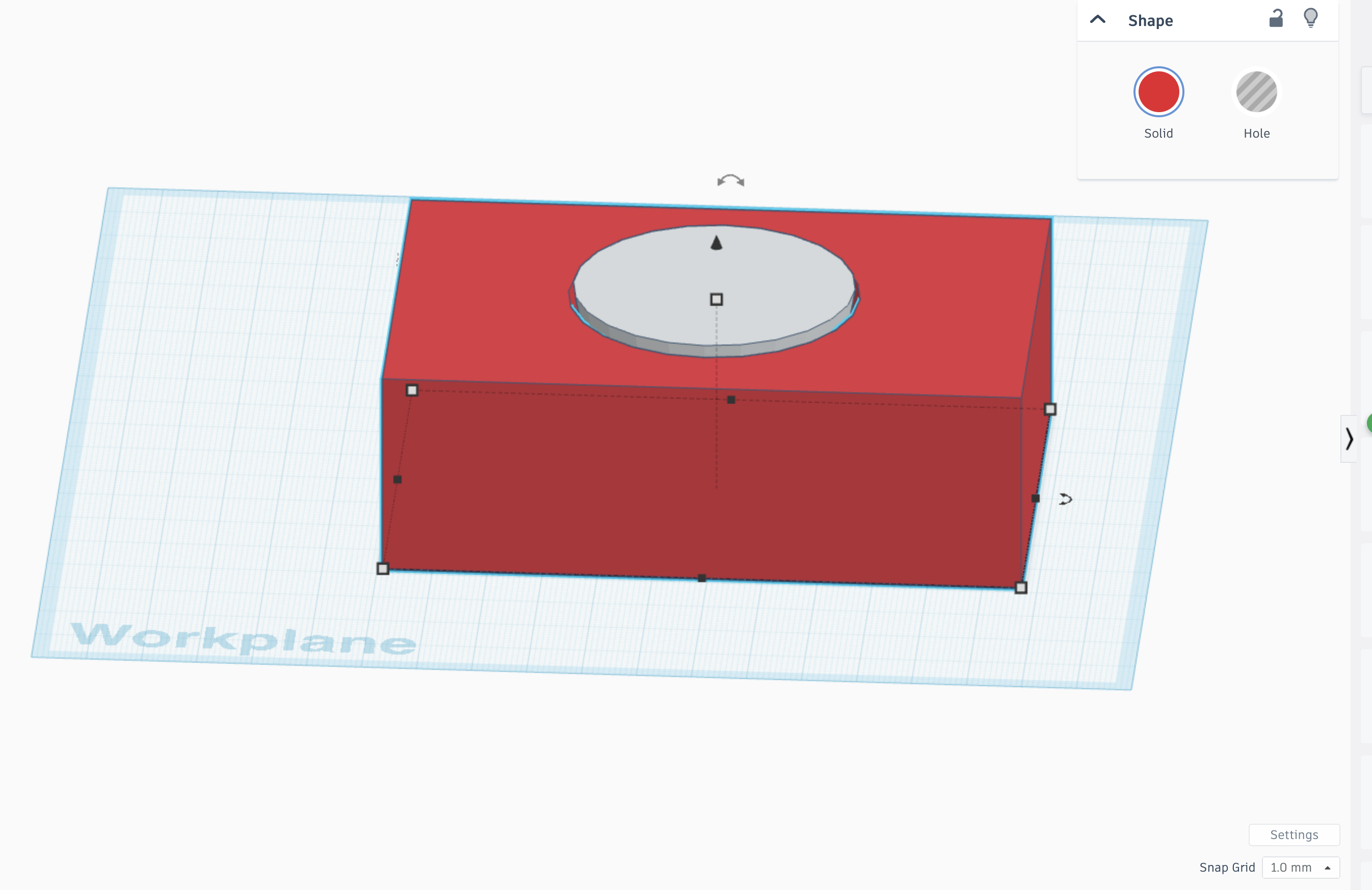
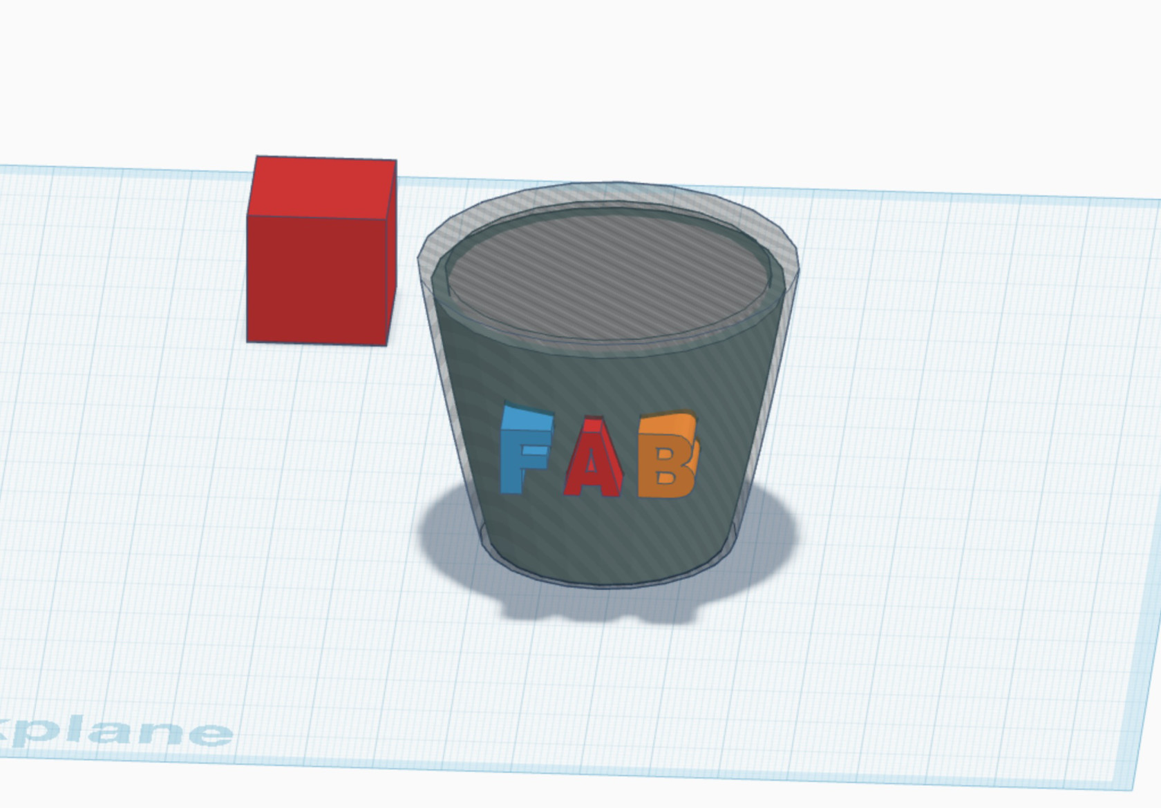
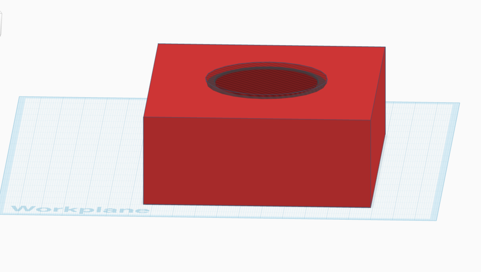
2. Creusement de l'Intérieur du Cup
Afin de retirer de la matière et obtenir l'espace intérieur du cup :
-
Nous avons ajouté un Box Hole (boîte en mode "trou").
-
Nous l'avons placé au centre de la forme paraboloïde et ajusté sa hauteur.
-
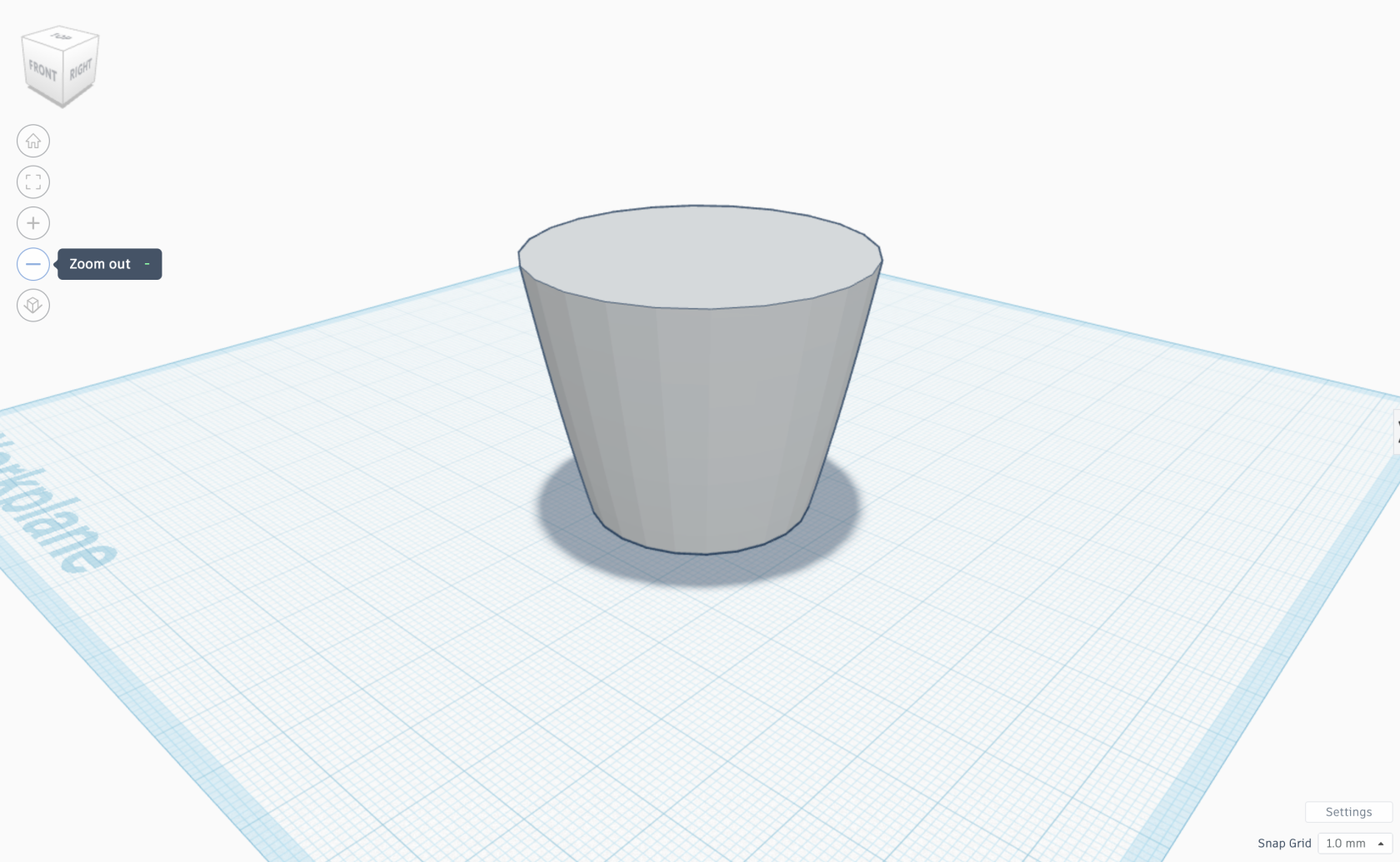
En utilisant l'outil Hide et en élevant le Box Hole, nous avons supprimé la matière nécessaire pour obtenir la forme principale du cup.
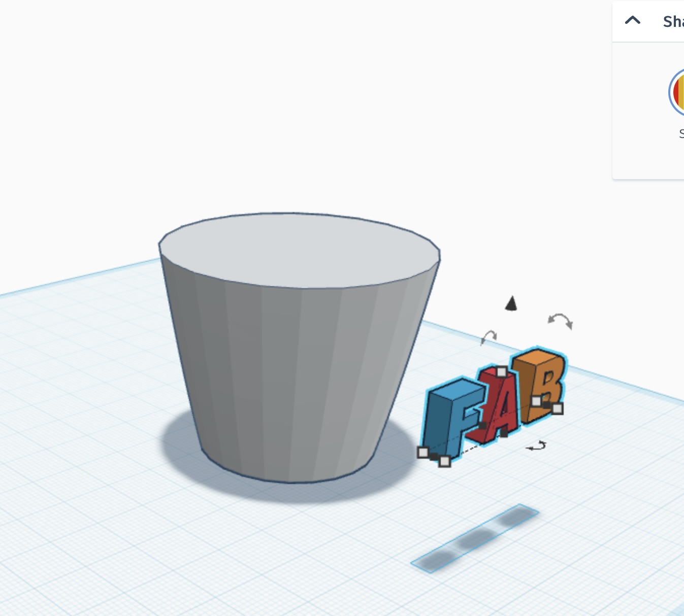
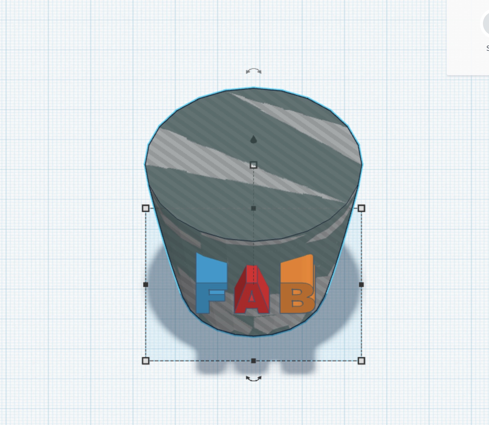
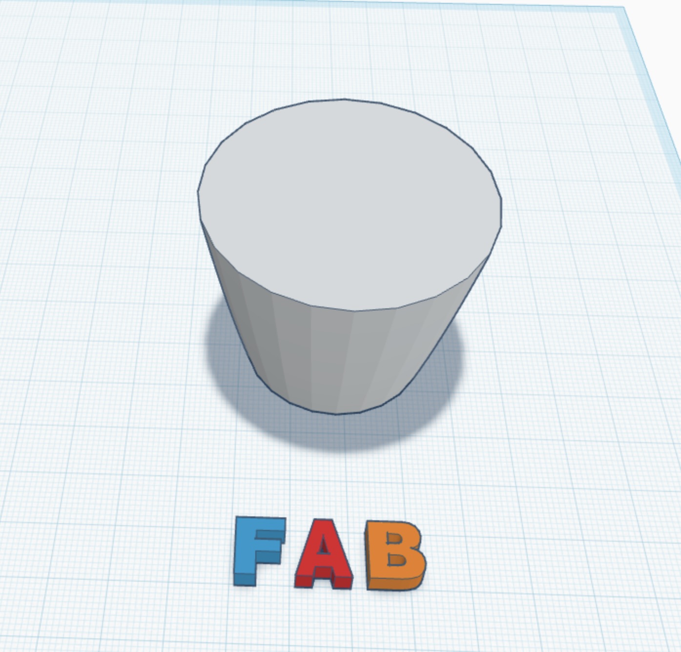
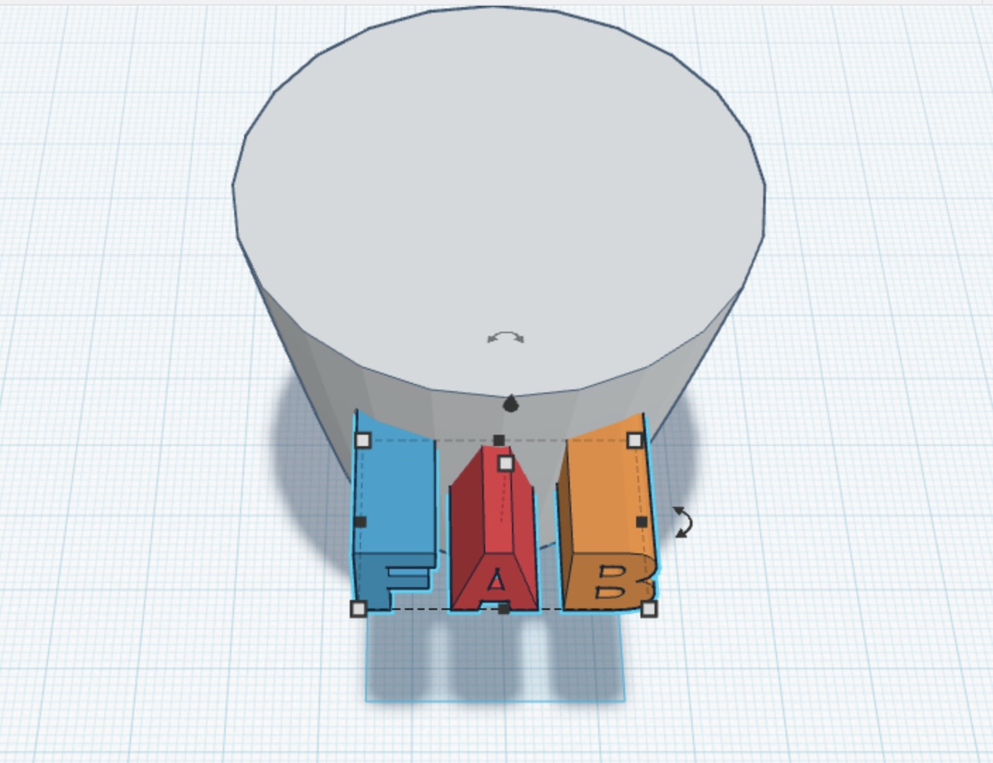
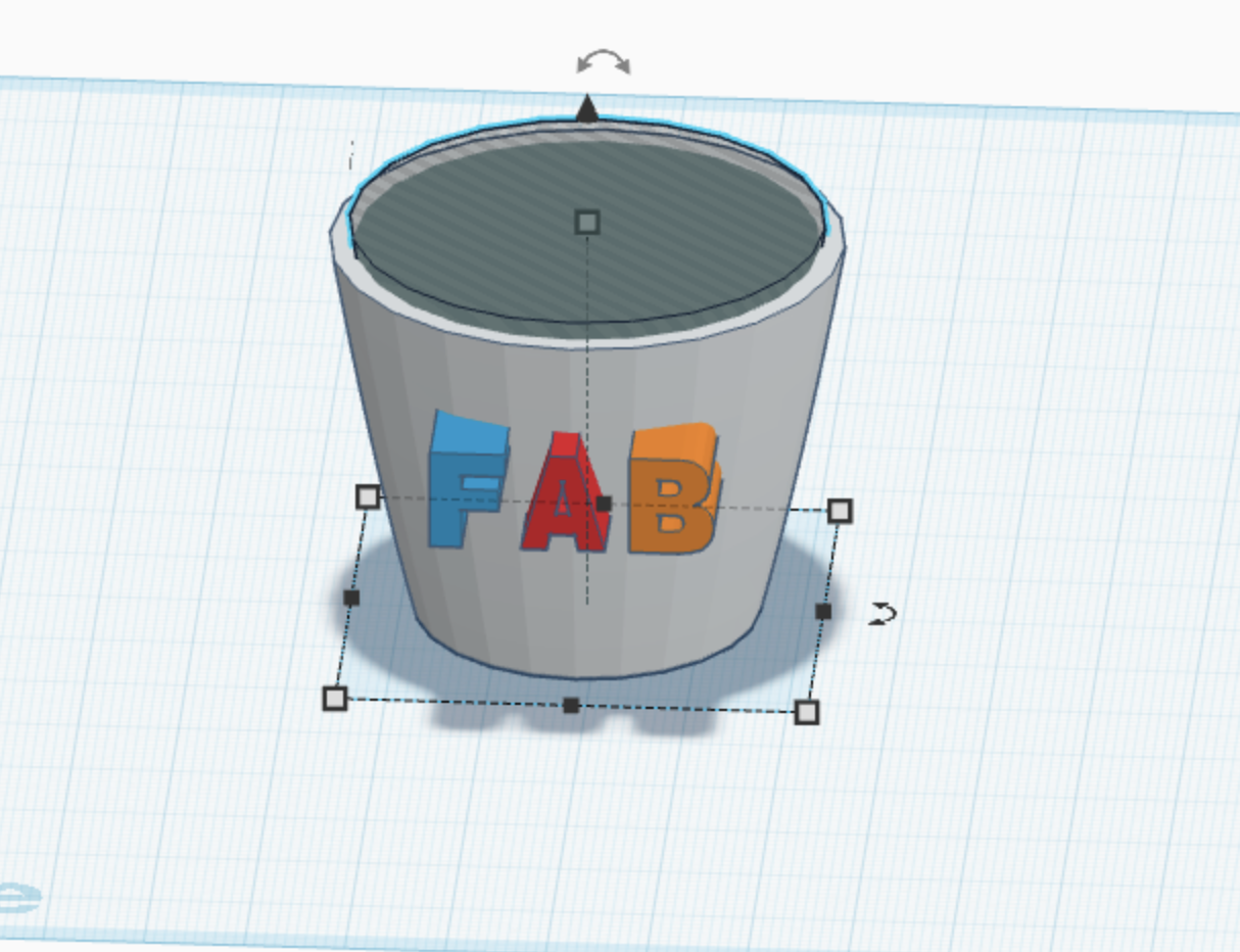
3. Ajout du Design (Texte FAB)
Pour personnaliser le cup, nous avons ajouté le texte "FAB" en suivant ces étapes :
-
Ajout des lettres individuellement.
-
Utilisation de la fonction Group pour fusionner les lettres et les déplacer ensemble sans les séparer.
-
Rotation et alignement du texte avec le centre du cup.
-
Application d'un bossage pour donner du relief aux lettres.
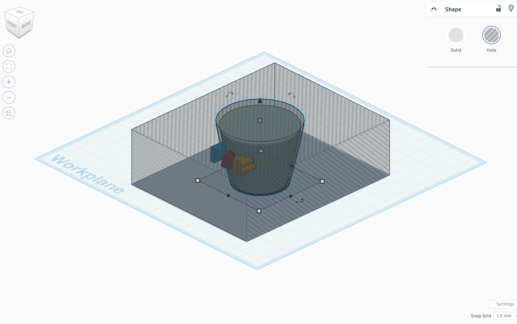
4. Perfectionnement de l'Intérieur du Cup
Afin d'affiner l'intérieur du cup et assurer un volume creux :
-
Nous avons copié la forme principale du cup en une version plus petite et plus haute.
-
Un cube a été ajouté pour créer plusieurs layers.
-
Nous avons ensuite groupé ces éléments et supprimé la matière superflue pour obtenir un cup creux.
5. Ajout de la Anse du Cup
Pour créer la anse du cup :
-
Nous avons utilisé une forme torus, puis effectué une rotation et ajusté ses dimensions.
-
Alignement du torus avec le cup.
-
Une partie du torus se trouvait à l'intérieur du cup, donc nous avons réalisé une retenue de matière :
-
Ajout d'une partie retenue du corps du cup.
-
Groupement de l'ensemble.
-
Suppression de la partie interne superflue.
6. Finalisation et Préparation pour l'Impression
Projet Finale:
- Concevoir un système d’alerte de température qui détecte une chaleur excessive avec thermomètre , déclenche une alerte visuelle avec une LED et active un ventilateur pour refroidir l’environnement.
- Ce système peut être utilisé pour protéger des équipements électroniques, surveiller une pièce, ou éviter la surchauffe d’un boîtier.

 LED S'ALLUME EN FONCTION DE LA TEMPERATURE :