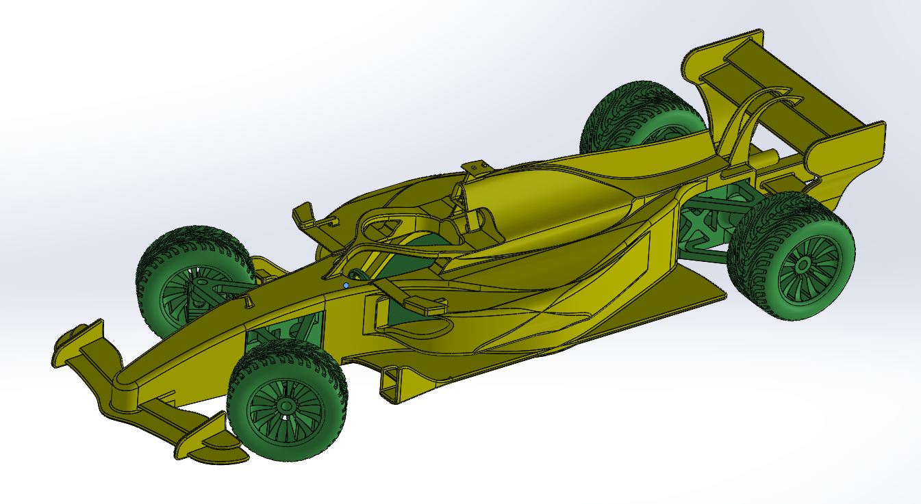
Formula 1 car - 2026 version : 1:10 scale
Introduction :
This project is about creating an accurate model of a 2026 Formula 1 car with a scale of 1:10, it involves using at least 2 different techniques of construction, and should at least includes 1 mechanism.
Choice of mechanisms :
- Wheel rotation : The primary functionality of a vehicle is being able to move, thus rotating wheels, in the form of a hinge relation whith axel of rotation.
- steering system : The second most important functionality of a vehicle is being capable of turning and changing directions, thus it was included to get more close to the real model, and it is done through a unique form of geometry.
1. Constructed Basic Parts
In this section, we break down the individual components that make up the vehicle's infrastructure. Each part is designed with specific tolerances to ensure that the mechanisms and assembly go smoothly.
Also, the dimensions are 1:10 scale as we mentioned before, real dimentions are found in FIA publications and regullations for 2026 season, so eveything is available to the public.
-
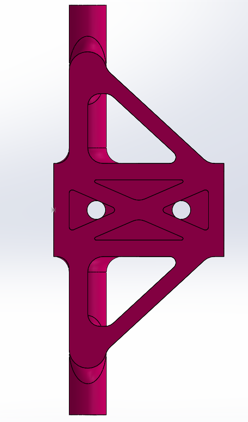
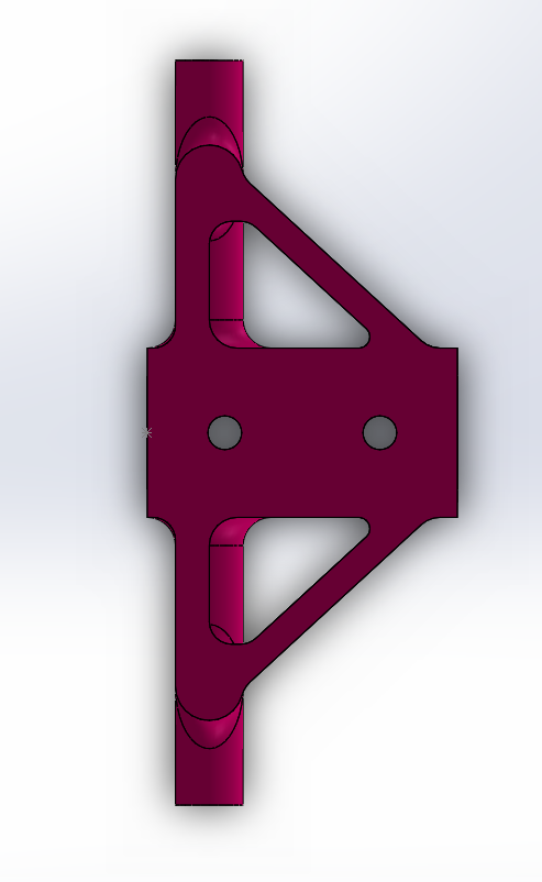
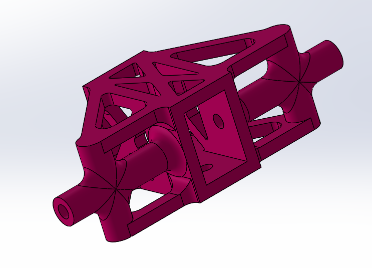
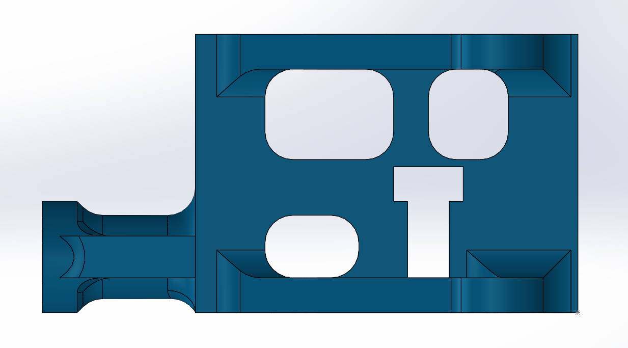
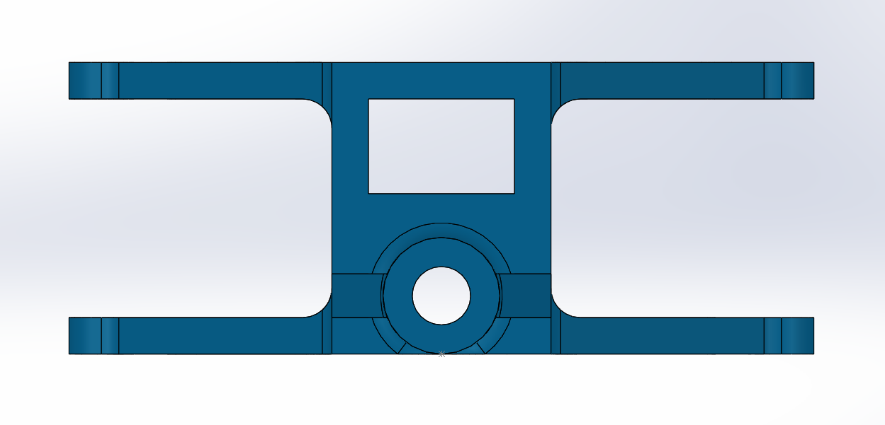
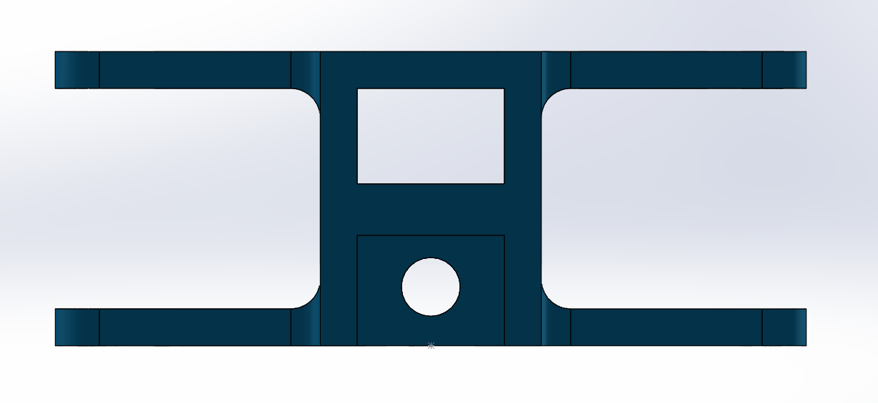
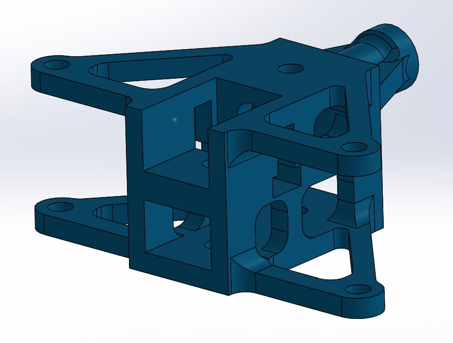
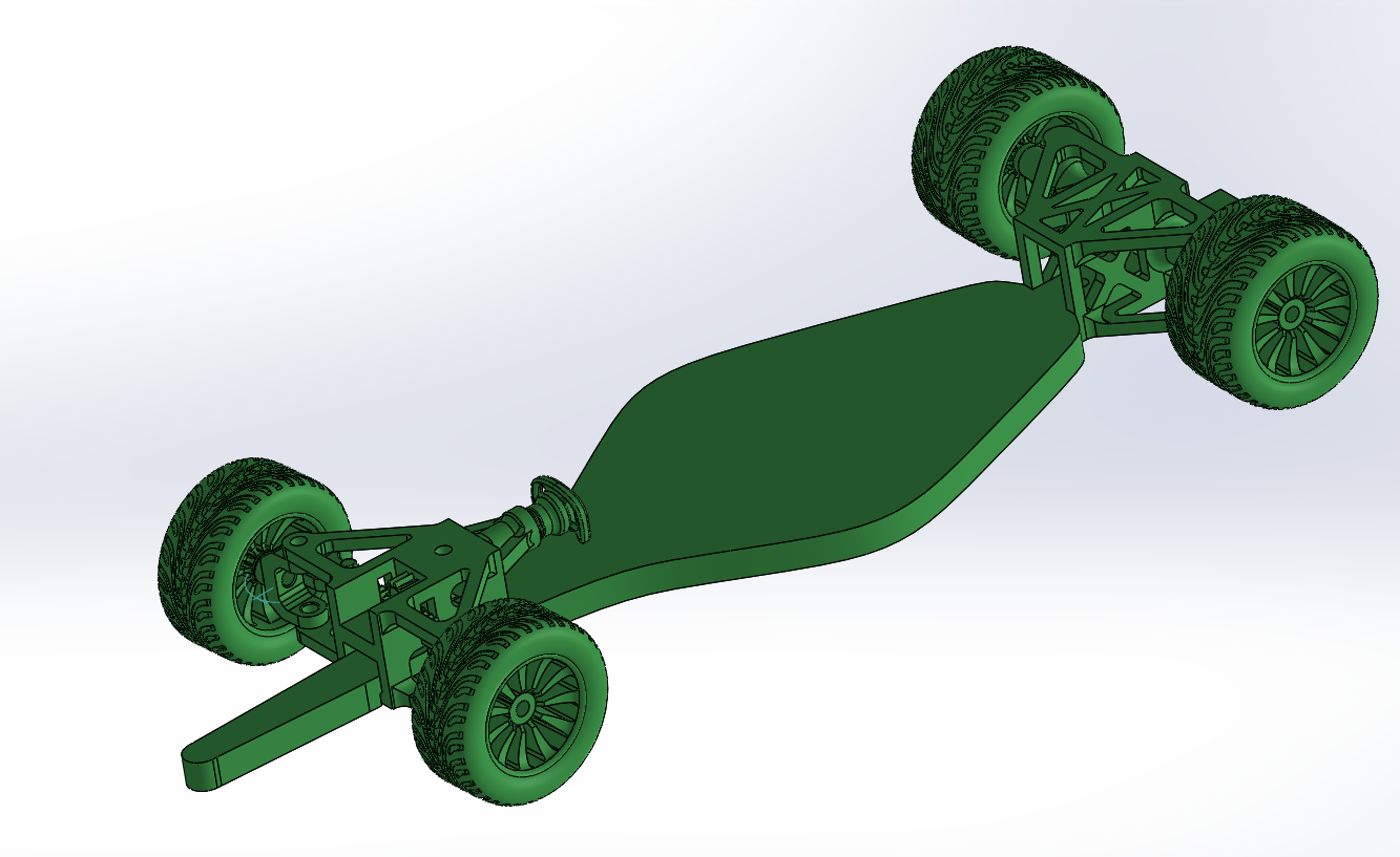
Front and back axels: These are most important parts of the design, they are the base of the mechanisms, they were constrcuted first, and other parts follow them , of course with a vision to how parts should fit and their size.
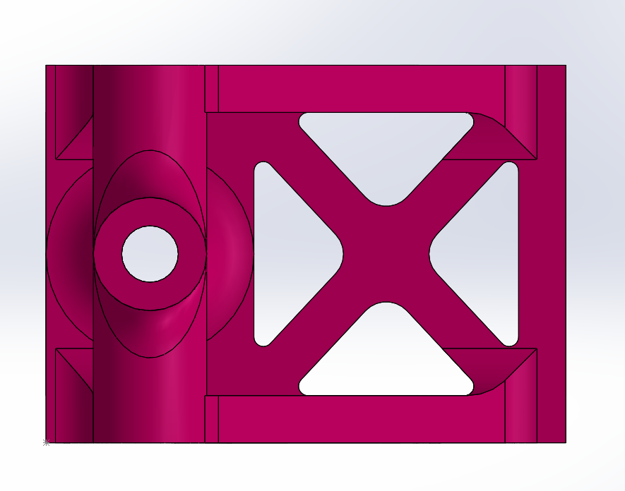
- Back axel top view :
- Back axel bottom view :
- Back axel side view :
- Back axel corner view :
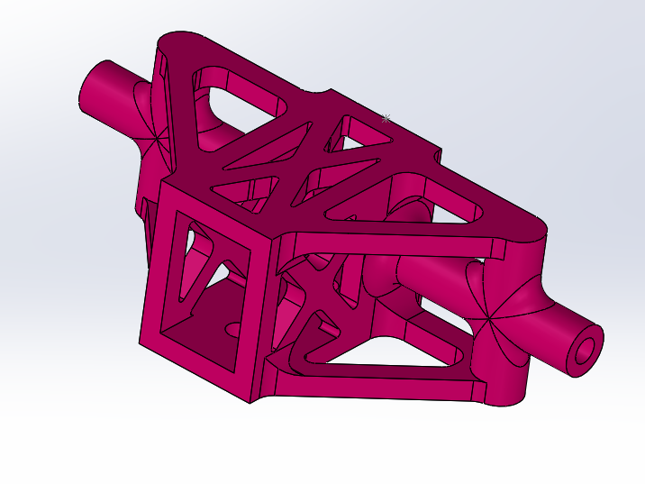
-back axel corner view :
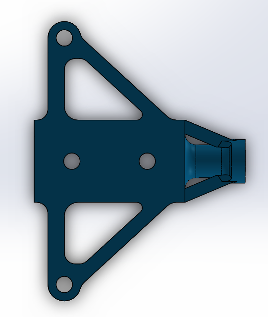
- front axel top view :
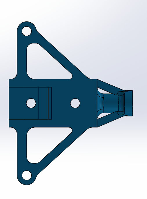
- front axel bottom view :
- front axel side view :
- front axel front view :
- front axel back view :
- front axel corner view :
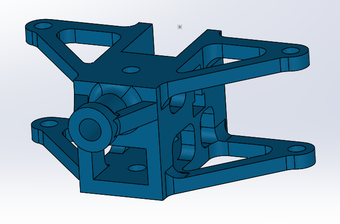
- front axel corner view :
-
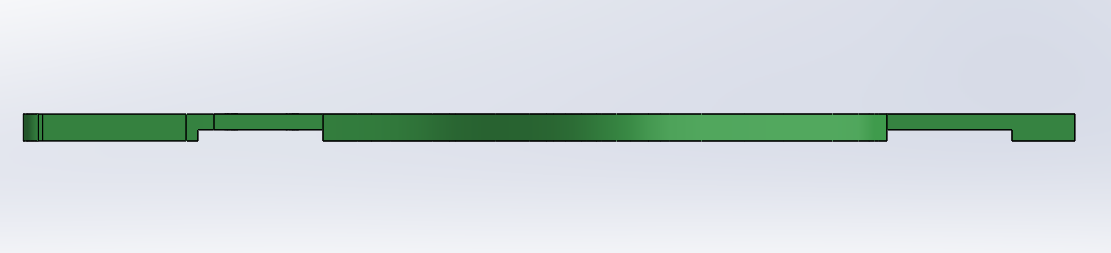
The Chassis : The backbone of the model. Machined from a solid block to handle the 500mm length and 140mm width, it features mounting points for the front and rear axels assemblies, and the base for the bodywork to sits on top.
- Top view :
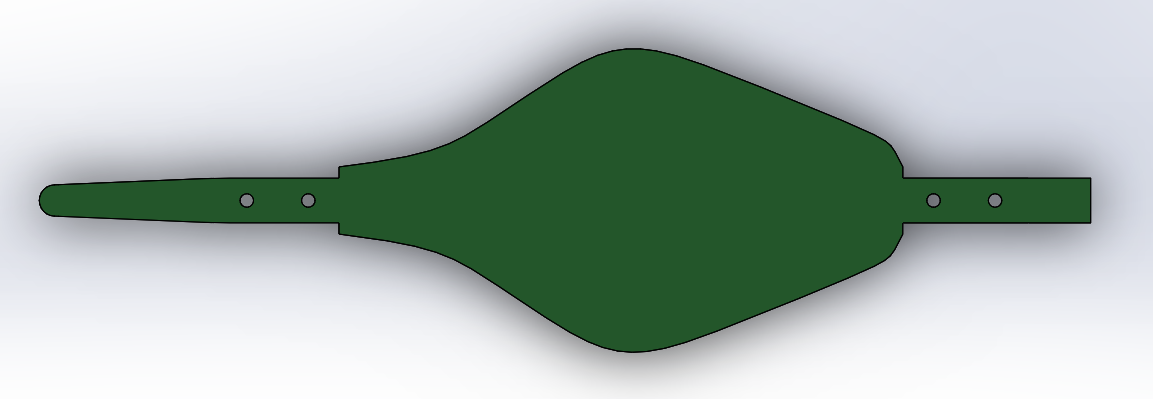
- Bottom view
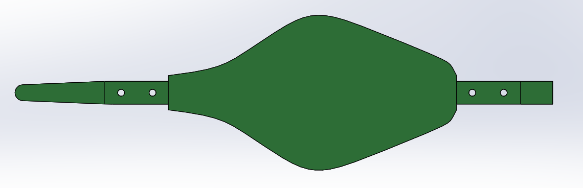
- Side view :
-
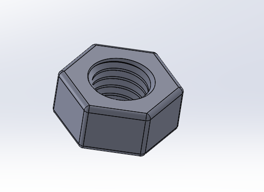
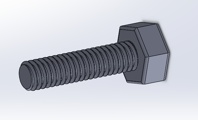
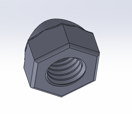
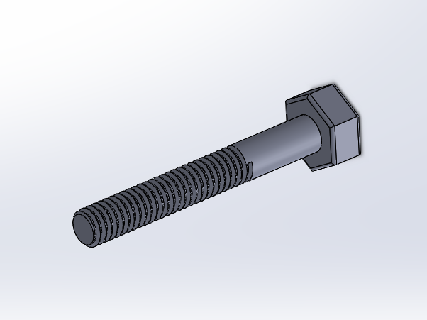
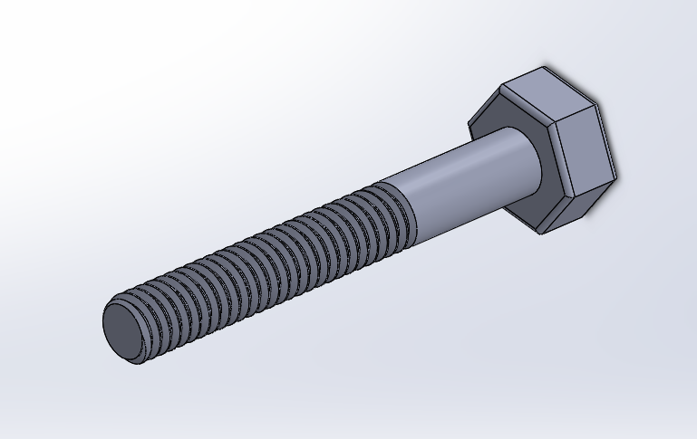
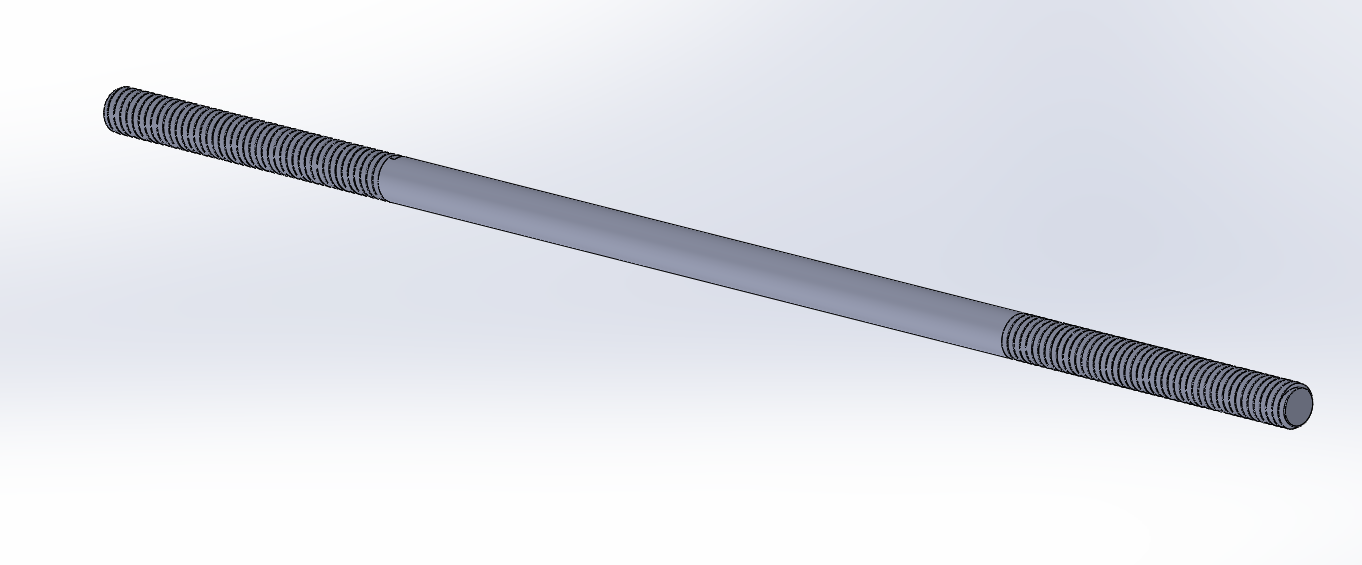
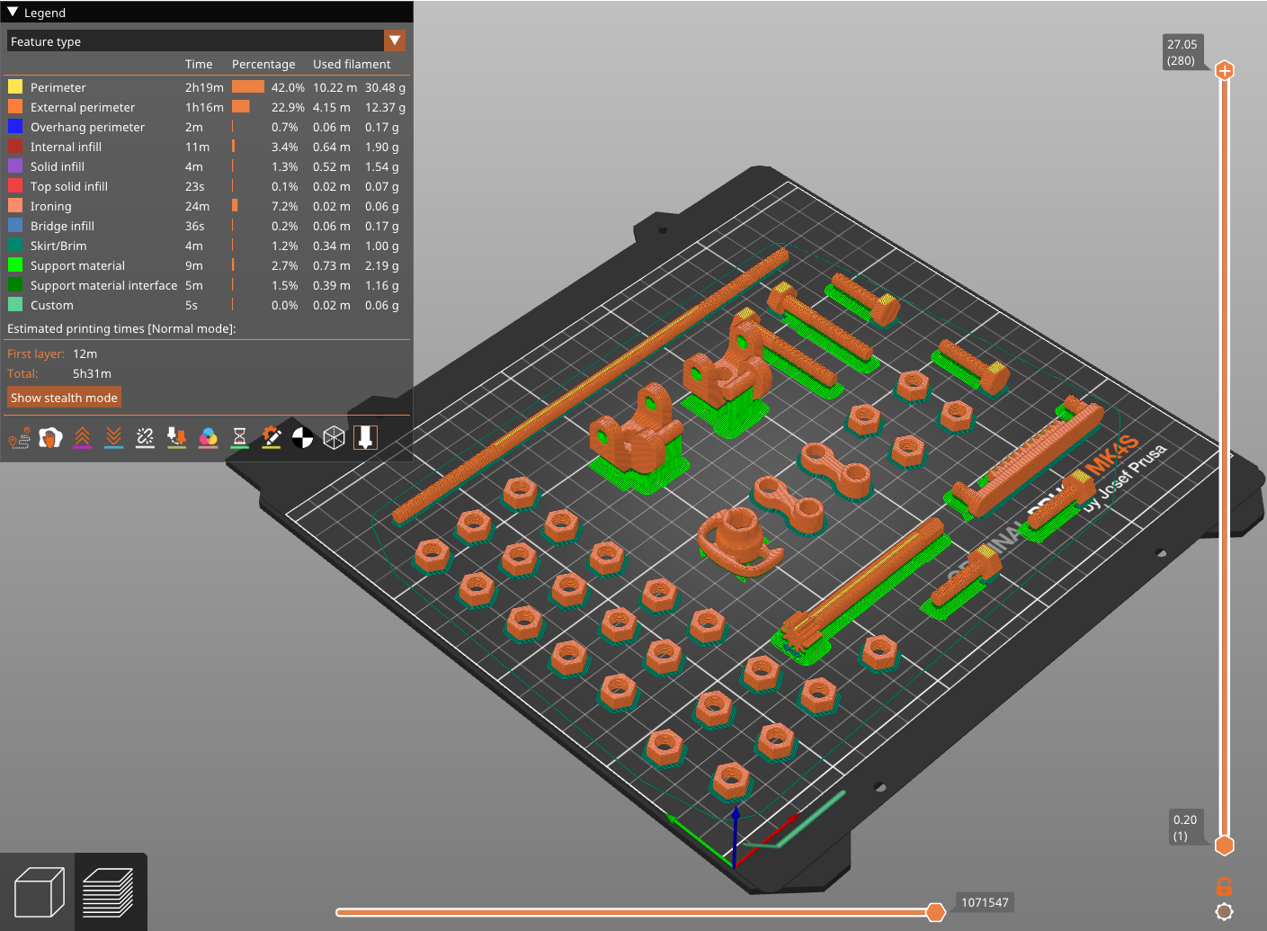
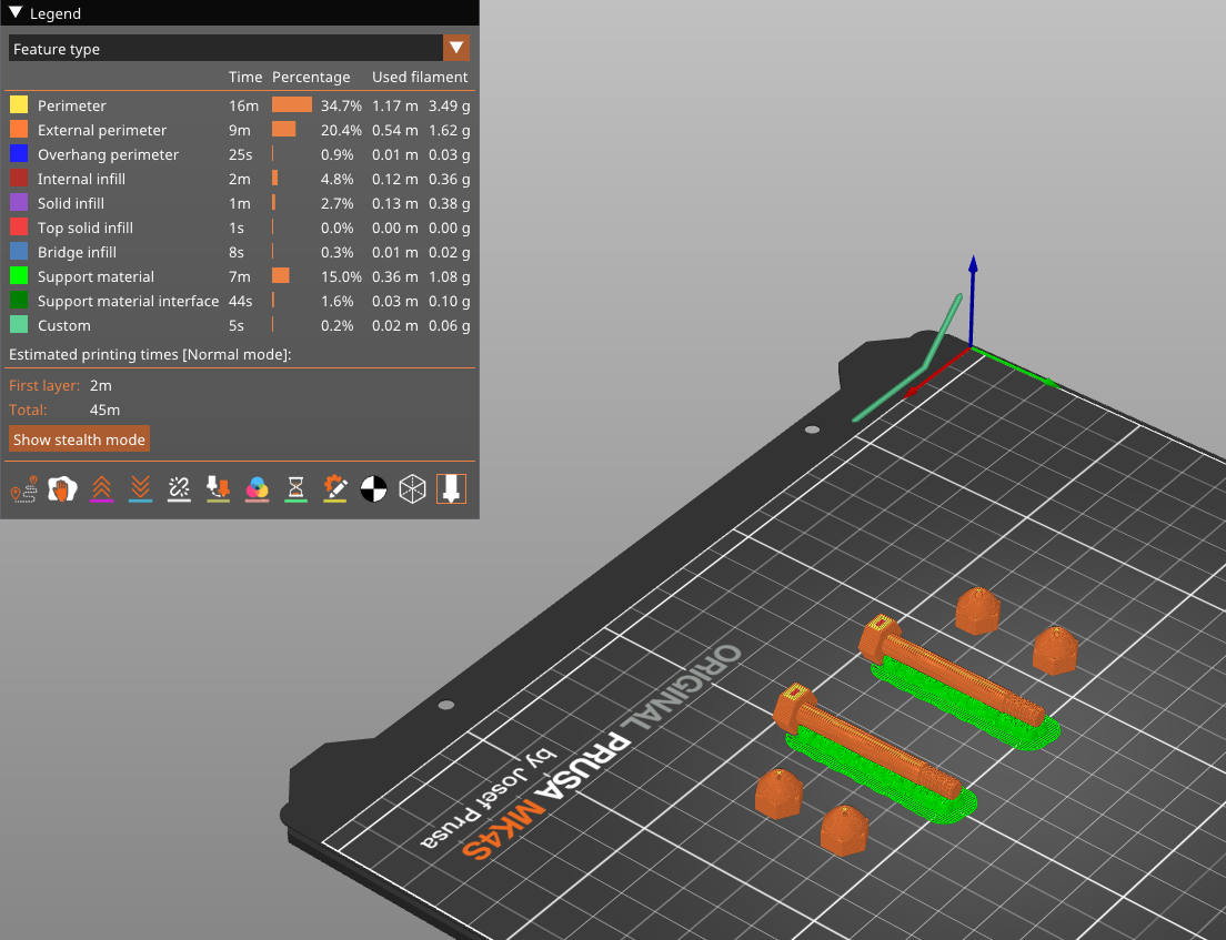
Fasteners (3D Printed Bolts and Nuts): Custom-threaded components designed with a 0.2mm tolerance and M6x1.0 profiles on 5.5mm diameter to ensure they can be hand-tightened without stripping the plastic threads.
-


2. Wheel Rotation Mechanism and conception
The rotation mechanism is designed as a journal bearing system. Rather than using metal ball bearings, the model utilizes the low-friction properties of smooth 3D-printed surfaces.
-
The Hub and Casing: The hub features a 5.5mm diameter shaft that passes through a 6mm diameter casing. This 0.5mm clearance ensures that the wheel can rotate freely even if there is slight thermal expansion or minor printing imperfections.


-
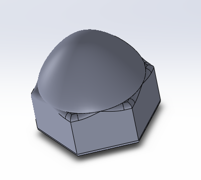
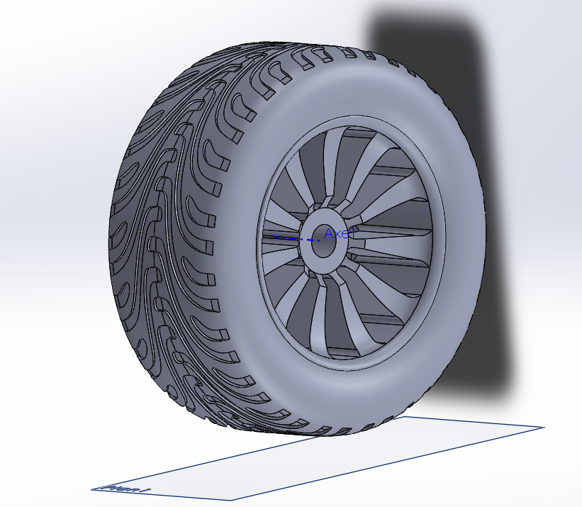
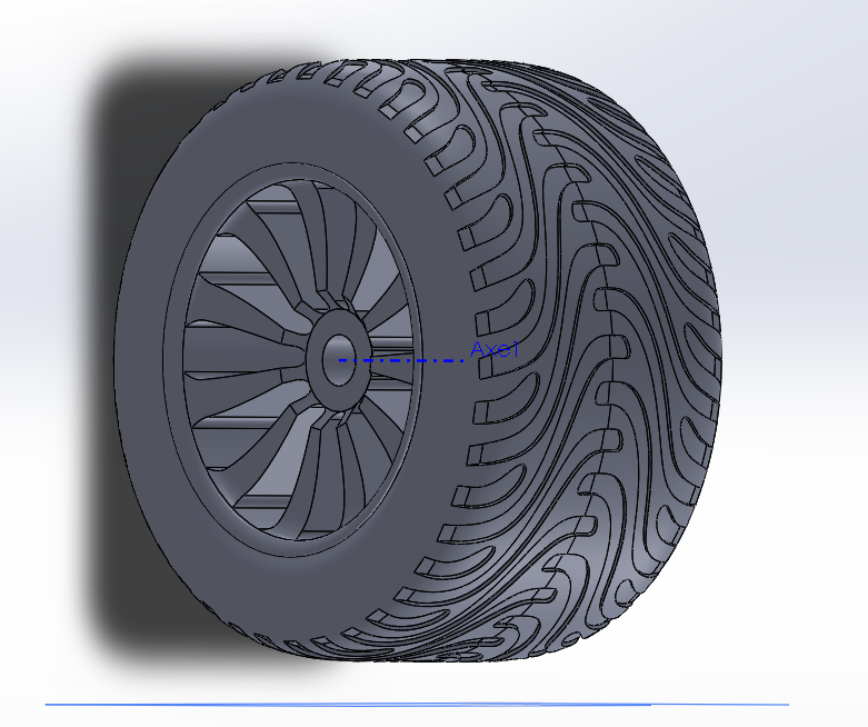
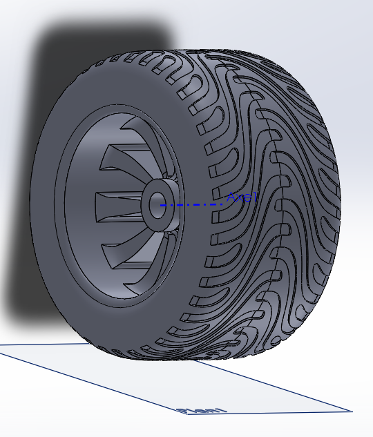
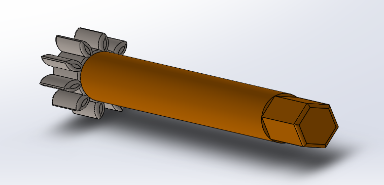
Axial Retention: To prevent the wheel from sliding off the axle, the end of the hub is threaded. A custom-designed hex nut is screwed onto the hub, securing the wheel while allowing it to spin on its y-axis, additionally center caps are designed also to hide the hubs, not to forget to mention that right side hubs are right handed and left side hubs are left threaded since we have a center lock system; wheels rotation and one side unscrewing/scerwing doesnt unscrew the nuts and center locks.

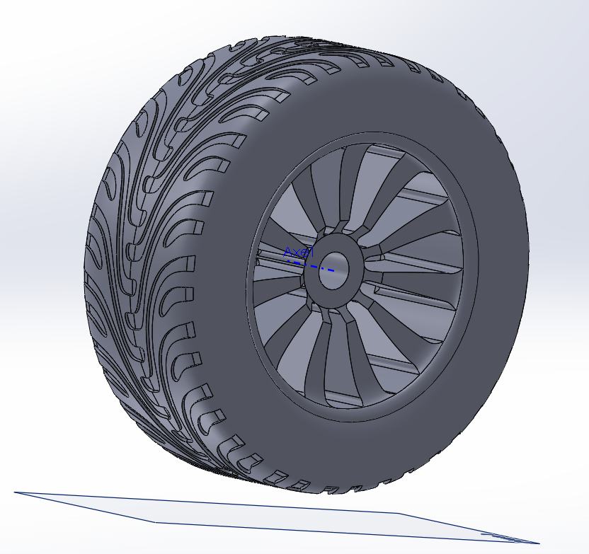
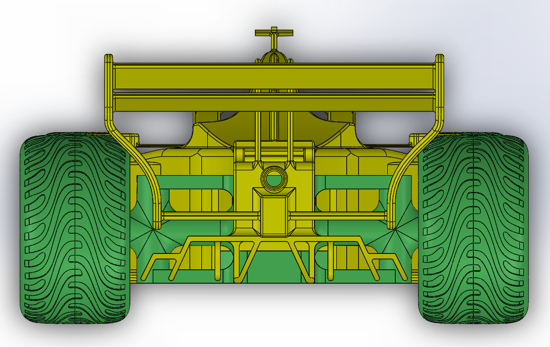
- Wheels : each wheel is unique, rear wheels are larger to provide more grip, front tires and skinniers to allow for smooth steering, tire threads and rims are different from right to left sides, which is related to wheight disturbution and water and debries paths the surface betwwen tires and road.


3. Steering System Mechanism and conception
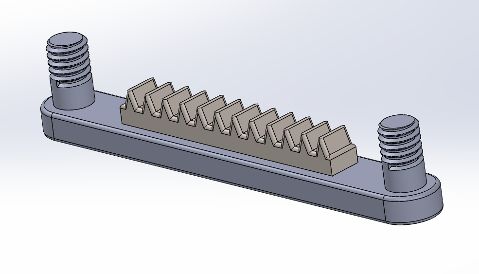
The steering follows a Rack and Pinion logic, which translates the rotational motion of the steering wheel into the linear motion of the racket to a rotational motion required to turn the front wheels.
-
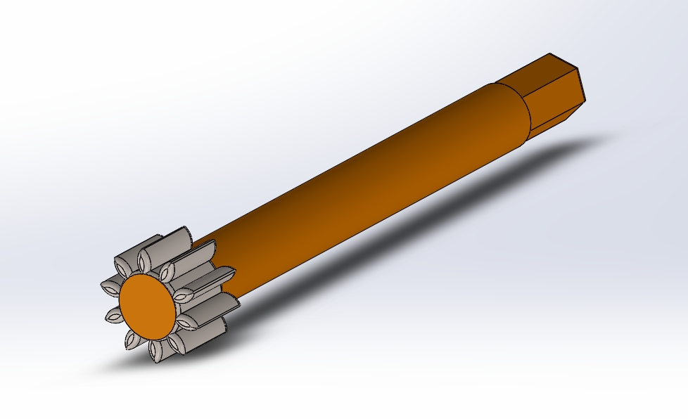
Pinion Gear: A small circular gear attached to the steering column. It is printed flat to ensure the teeth have maximum shear strength, at the other side of its hub is hex shaped to mount to the steering wheel, hub was designed then mounted to the gear.

-
The Rack (Racket): A linear gear that slides horizontally across the front of the chassis. It features a custom gear tooth profile that matches the pinion and mounts for the tie rod, housing of teeths was made firs and mounted to them, the end mounts are threaded to privent tie arms from coming off when the car is upside down or from vibration.
-
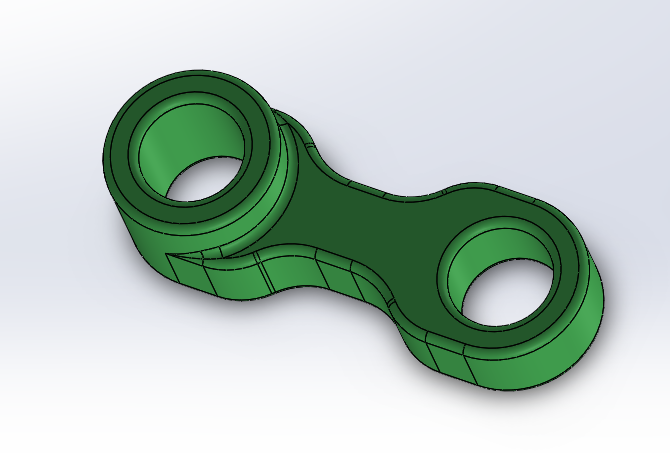
Tie Rods: These connect the ends of the rack to the steering arms. They use a hinge relation to allow the steering arms to move and rotate while the rack moves left or right.
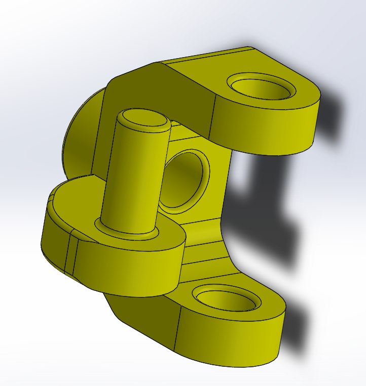
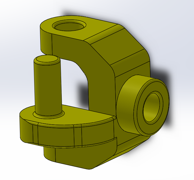
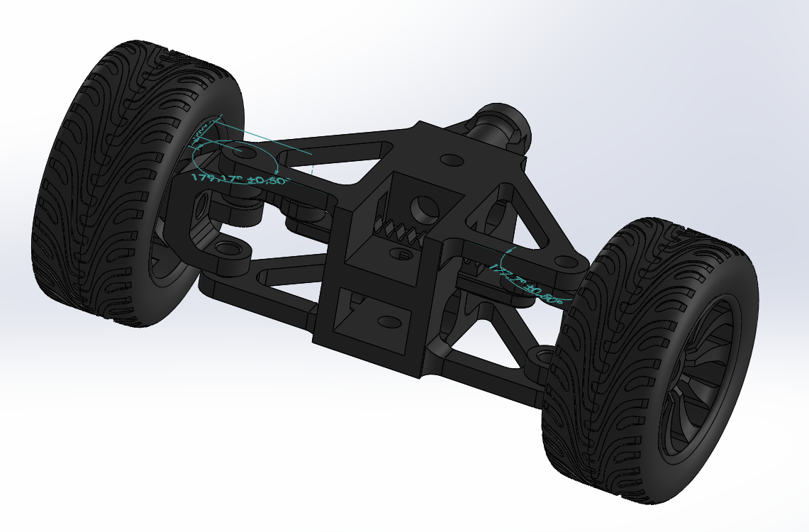
- Steering arms: the component that gives life to the system and define the steering type, for formula 1 cars, we have a slightly anti-ackerman which means the steering arms at neutral are angled away from the rear axel, which define depending on the position of the rack (infront or behind the axel of rotation) the geometry we are trying to achieve, for this part, there are 2 mirrored copies, one for the right side and the other for the right side.

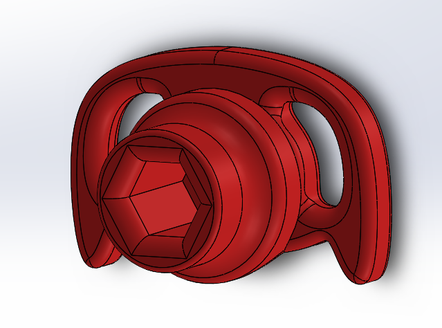
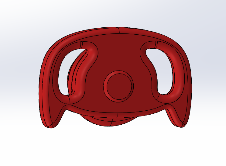
- steering wheel: following the shape of the pinion hub for mounting, and the 2025 version since a smaller 2026 version isn't gonna resist the load.


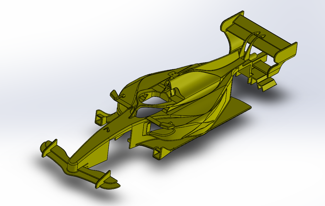
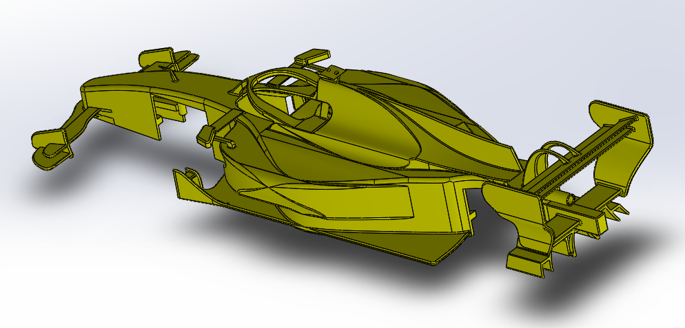
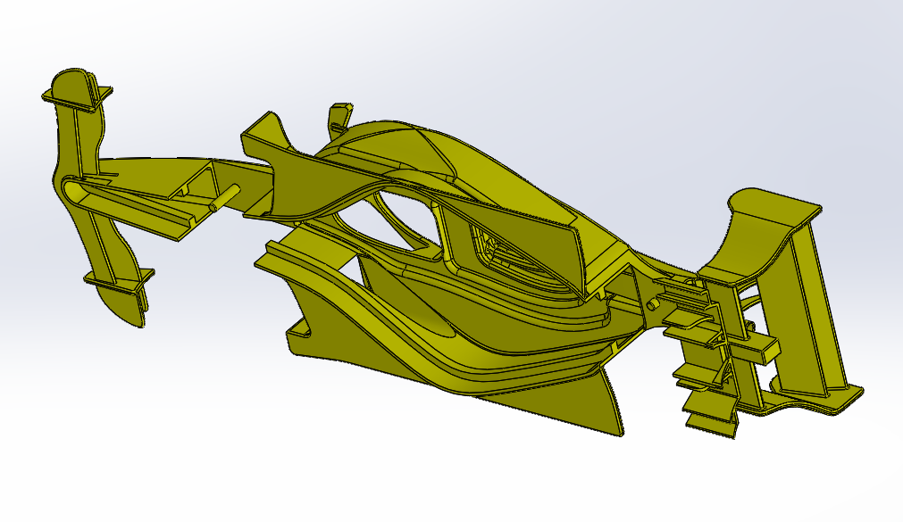
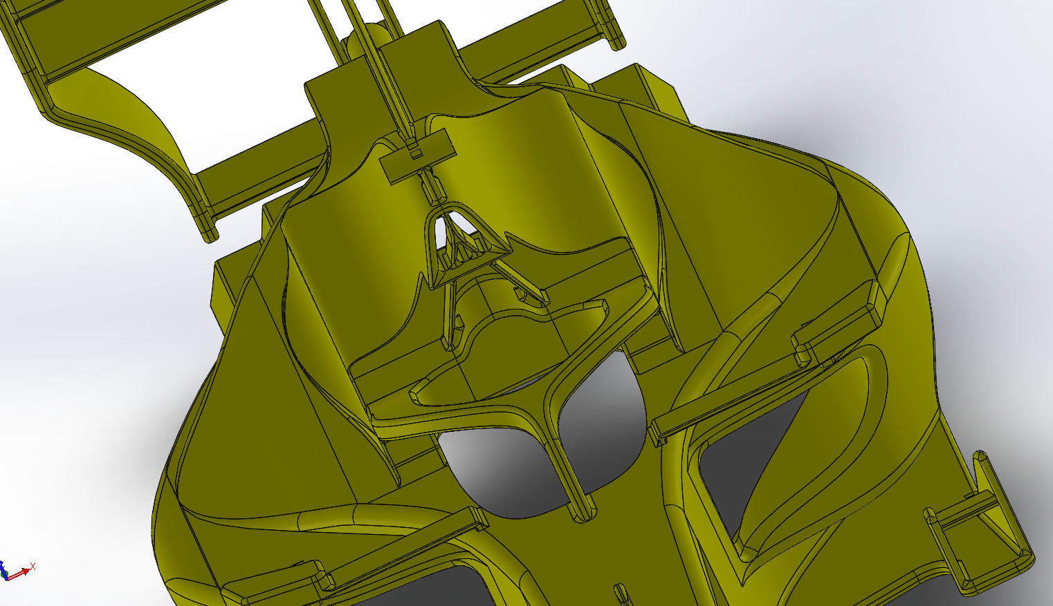
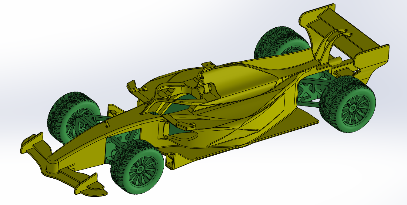
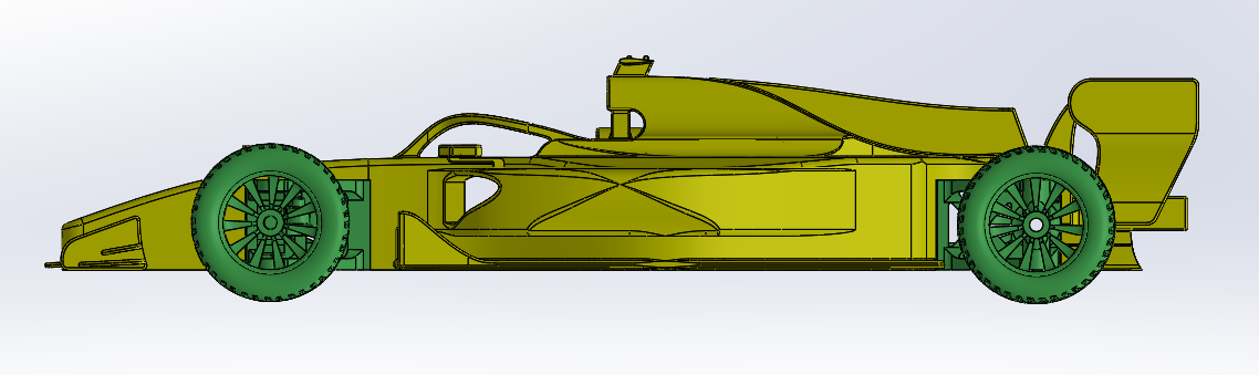
4. Bodywork
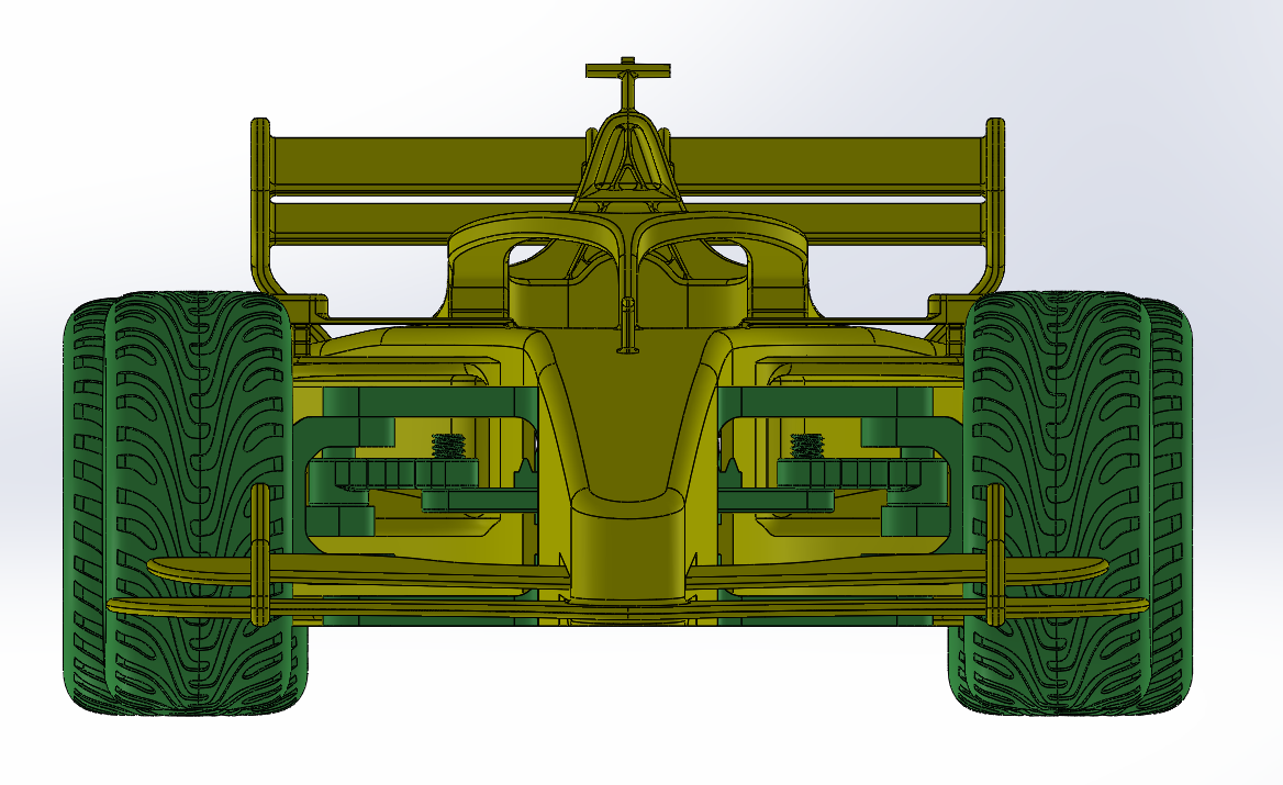
The bodywork of the 2026 Formula 1 model serves as the critical interface between the vehicle's mechanical core and the surrounding airflow, designed to manage complex air paths across the 500mm chassis. The front and rear wings are the primary aerodynamic drivers, where the angle of attack—the tilt of the wing profiles relative to the oncoming wind—is carefully tuned to balance the generation of downforce against the penalty of drag. A steeper angle increases the pressure differential between the upper and lower surfaces, "pushing" the tires into the track for better cornering grip. Between these wings sits the Halo, a structural safety element that presented a unique aerodynamic challenge; its curved geometry was modeled to minimize turbulent "wake" that could interfere with the air path directed toward the rear wing and engine intake. By integrating these 3D-printed surfaces, the model directs air in a cohesive stream that starts at the front wing, flows around the suspension arms, and is accelerated through the rear diffuser to maximize high-speed stability. a shelf is added around to provide sitting on the chassis.
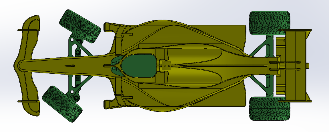
5. Phase 1: Front Axle Assembly & Geometry Refinement
The first assembly focused exclusively on the steering rack, pinion, hubs, and tie rods. This "isolated" assembly was critical for fixing the steering system's sensitivity and accuracy.
-
Rack Position & Longitudinal Distance: By assembling the rack relative to the front axle, the distance between the two was adjusted to minimize Bump Steer. If the rack is too far forward or backward, the wheels toe in or out as the suspension moves.
-
Tie Rod Length & Sensitivity: The tie rods were adjusted to set the Initial Toe. Shorter tie rods increased steering sensitivity (making the car "darty"), while longer rods stabilized the car for straight-line speed.
-
Anti-Ackermann Geometry: In high-speed F1 racing, "Anti-Ackermann" (where the outer wheel turns more than the inner wheel) is sometimes used to counteract tire slip angles. By adjusting the distance between the tie rod mounting point and the hub's pivot axis, the "aggressiveness" of the steering arc was finalized.

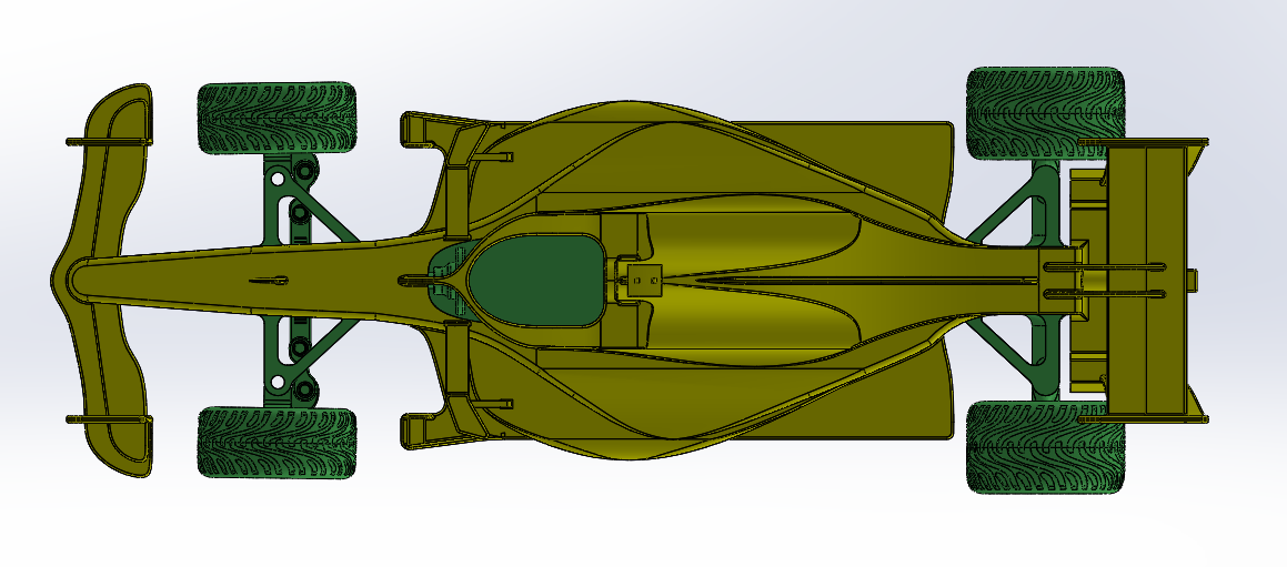
6. Phase 2: Full Chassis Integration (Front & Rear Axles)
Once the steering was functional, the front assembly was mated with the CNC-machined wooden chassis and the rear axle components.
-
Wheelbase Alignment: This assembly ensured the front and rear axles were perfectly parallel. With a 500mm length, any slight twist in the wooden chassis would cause the car to "crab-walk."
-
Load Distribution: This phase tested the 3D-printed bolts and nuts under the weight of the full chassis. It confirmed that the 0.5mm tolerances allowed the parts to sit flush against the wood without creating mechanical stress points.
-
Drive Train Check: The rear axle rotation was verified against the chassis clearance to ensure that vibrations from the wooden frame wouldn't interfere with the smooth rotation of the 3D-printed hubs.

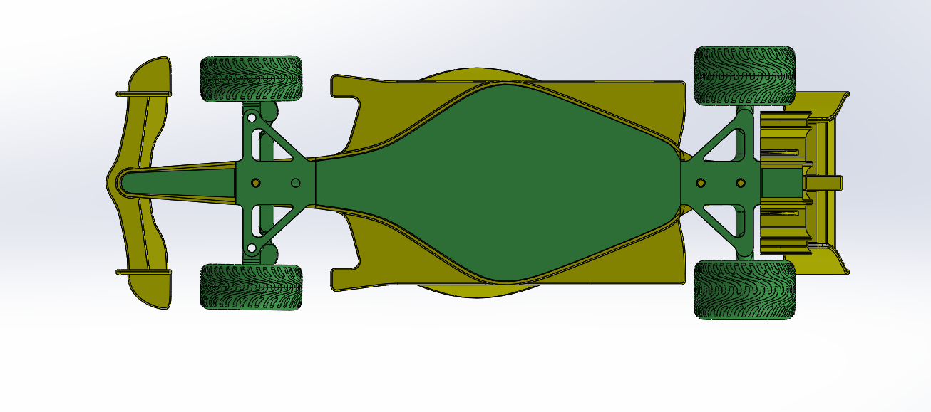
7. Phase 3: Final Assembly & Bodywork
The final stage involved "clothing" the mechanical chassis with the aerodynamic bodywork.
-
Clearance Verification: The primary goal here was ensuring the front wheels could reach Full Lock (maximum turning angle) without hitting the inside of the front wing or the sidepods, and also don't collide with front wings and sidewings.
-
Access Points: The assembly revealed where the bodywork needed "cut-outs" to allow for battery swaps or steering adjustments without having to dismantle the entire CNC chassis.
-
Aero-Mechanical Synergy: The final model was checked to ensure that the 3D-printed bodywork didn't obstruct the linear travel of the steering rack.
8. Manufacturing and Printing Parameters
Choice of construction methods :
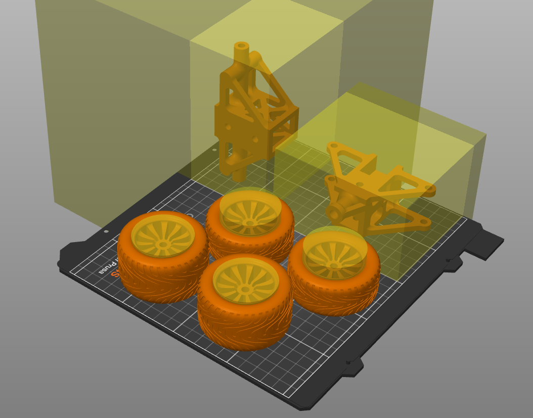
- 3D printing PLA : It fulfill the needs and complex geometry of our parts including front and back axels, steering arms, tie rods, tires, rims, racket, pinion, and the steering wheels. bolts and nuts were also 3D printed.
- CNC machine - wood : due to the size of the model which is 1:10 scale of a real car, the length of the model was expected to be around 500mm which is too large of 3D printer available, and this involves the parts that can't be cut into smaller pieces , thus the chassis which is meant to be strong enough to sustain the wheight of the car and vibrations and load in general from all directions, so laser cut wood won't cut it becuase of the height of wood plates that work with it (3mm to 6mm), so the CNC machine was chosen for this.
To ensure the structural integrity of the 1:10 scale Formula 1 model, the 3D printing parameters were strategically assigned to balance weight, surface finish, and mechanical strength. Since the model relies on a mix of aerodynamic shells and high-stress mechanical components, the following settings were utilized:
-
Aerodynamic Bodywork (Lightweight Focus):
-
The main fairings, engine cover, and wings were printed with 5% infill to minimize weight and reduce the load on the CNC-machined chassis.
-
A setting of 2 perimeters was used to provide a smooth outer shell while keeping the parts light.
-
-
Wheel Assemblies (Variable Strength):
-
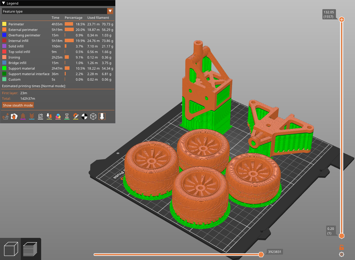
Tires: These were printed with 10% infill and 3 perimeters to provide durability while allowing for slight material compliance.
-
Rims: These utilized 20% infill and a higher count of 5 perimeters to ensure the center hole is rigid enough to hold the custom-threaded hubs without cracking under torque.
-
-
Mechanical and Structural Components (High-Stress):
-
Critical components including the axles, steering rack, pinion gear, steering arms, and tie rods were printed with 30% to 40% infill.
-
These parts utilized 5 perimeters to ensure that smaller elements, such as the rack teeth and M6x1.0 threads, consist of solid plastic for maximum shear strength.
-
| Part Category | Infill Percentage | Perimeter Count | Engineering Purpose |
| Bodywork & Wings | 5% | 2 | Weight reduction & low center of gravity. |
| Tires | 10% | 3 | Surface durability & weight balance. |
| Rims | 20% | 5 | Structural support for center-lock hubs. |
| Mechanisms & Axles | 30% - 40% | 5 | Impact resistance & thread durability. |
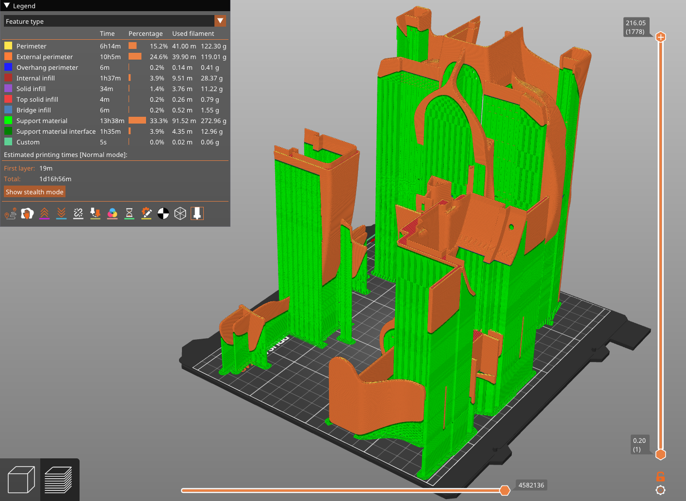
For the bodywork, the model was too big for a regular printer, so it had to be cut intro 3 parts, front 151mm, middel 216mm and rear 131mm, moreover Male-Female fittement was added between the 3, and 4mm holes for screws that will be driven into the wood with a screwdriver, 2 each for front and rear parts, 4 for middle part, made them in a way they are accessible.
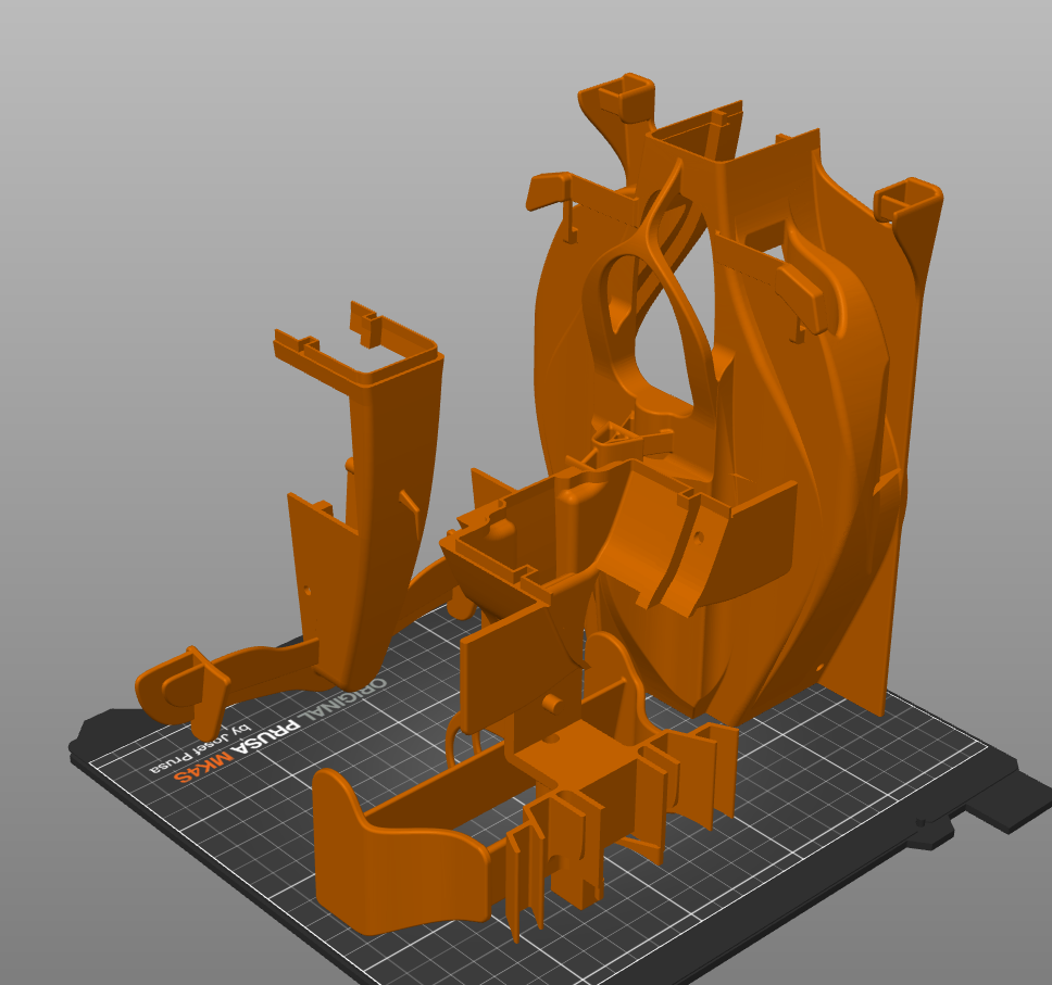
as for their print, i changed Z-distance to 0.15mm to ensure support hold the body tight, along increasing overhang parameter to 72° degrees for better support for tall curved structer, and prevent it from falling, i couldn't do organic support (which is suited for this because it would go out of range for the printer.
Conclusion :
This project successfully demonstrates the integration of advanced digital manufacturing techniques to recreate the complex mechanical and aerodynamic profile of a 2026 Formula 1 car at a 1:10 scale. By combining CNC-machined wood for structural rigidity with high-precision 3D printing for intricate components, the model achieves a balance between durability and authentic detail.
The core success of the project lies in the functional execution of its primary mechanisms:
-
Mechanical Integrity: The wheel rotation system utilizes custom-threaded, center-locking hubs with directional threading (right-hand and left-hand) to ensure operational stability, while the journal bearing design proves that 3D-printed tolerances can effectively replace traditional metal bearings in scale models.
-
Steering Precision: The implementation of a Rack and Pinion system allowed for a deep exploration of steering kinematics. Through iterative assembly phases, the geometry was refined to incorporate Anti-Ackermann characteristics and optimized tie-rod sensitivity, mirroring the high-performance handling of a real F1 chassis.
-
Aerodynamic Realism: The bodywork successfully integrates safety features like the Halo with performance elements like adjustable wings and diffusers, ensuring that the air paths complement the mechanical layout without compromising wheel clearance.
Ultimately, this model serves as more than a static replica; it is a functional engineering study. The tiered assembly process—from isolated axle refinement to full chassis integration—validated the design’s tolerances and structural choices. This project confirms that even at a reduced scale, the principles of F1 engineering—aerodynamics, precise geometry, and material synergy—can be effectively simulated through a thoughtful combination of modern construction methods.