Journal de bord
Jour 1 & 2 : Documentation des capteurs
Fonctionnement des capteurs :
Infrarouge :
"Le capteur émet un faisceau infrarouge, dont la longueur d’onde est définie en fonction du gaz ciblé. Lorsque ce gaz passe devant le faisceau, il va absorber une partie de son rayonnement. L’intensité mesurée va baisser. Celle-ci est comparée à une intensité de référence pour permettre d’établir une concentration." source ici
Le capteur électrochimique est composé d'un semi conducteur choisi par rapport au gaz que l’on souhaite mesurer, dont la résistance change en fonction des gaz présents et de leur concentration. Le courant électrique produit peut être mesuré par et traduit en concentration de gaz. Cependant d'autres molécules peuvent générer les mêmes réactions, il est alors impossible de les différencier. De plus ces capteurs s'usent au cours du temps.
Grove Capteur de gaz MQ2 (Seeed) : https://wiki.seeedstudio.com/Seeed_Gas_Sensor_Selection_Guide/
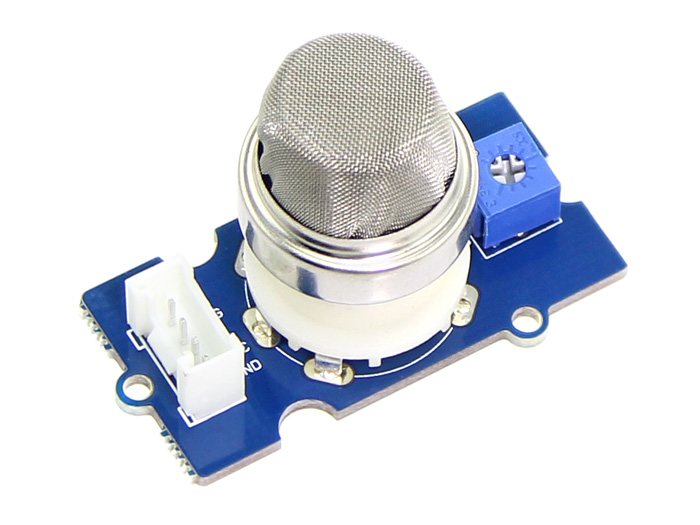
- Gaz cible : GPL, butane, propane, méthane, alcool, hydrogène, fumée
- Classe : Electrochimique
- Champs d'application : Sécurité et application domestique/au travail
- Plage de détection : GPL & Propane : 200-5000 ppm, Butane : 300-5000 ppm, Méthane : 5000-20000 ppm, H2 : 300-5000 ppm, Alcool : 100-2000ppm
- Tension de fonctionnement : 5V
- Interface : Analogique
Code capteur MQ2
void setup() {
    Serial.begin(9600);
}

void loop() {
    float sensor_volt;
    float sensorValue;

    sensorValue = analogRead(A0);
    sensor_volt = sensorValue/1024*5.0;

    Serial.print("sensor_volt = ");
    Serial.print(sensor_volt);
    Serial.println("V");
    delay(1000);
}
Grove Capteur de gaz MQ9 : https://wiki.seeedstudio.com/Grove-Gas_Sensor-MQ9/
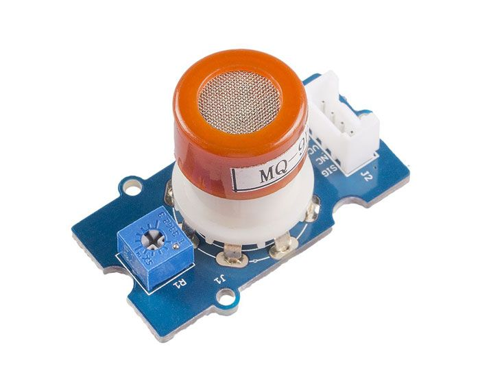
- Gaz cibles : GPL, CO, CH4
- Classe : Electrochimique
- Caractéristiques : grand champ de détection, stable et longue durée de vie, haute sensibilité
- Champs d'application : Sécurité et application domestique/au travail et dans l'industrie
- Plage de détection : GPL & Propane : 200-20000 ppm
- Tension de fonctionnement : 5V
- Interface : Analogique
Code MQ9
void setup() {
    Serial.begin(9600);
}

void loop() {
    float sensor_volt;
    float sensorValue;

    sensorValue = analogRead(A0);
    sensor_volt = sensorValue/1024*5.0;

    Serial.print("sensor_volt = ");
    Serial.print(sensor_volt);
    Serial.println("V");
    delay(1000);
}
Capteur Grove CO2, Température & humidité SCD30 : https://wiki.seeedstudio.com/Grove-CO2_Temperature_Humidity_Sensor-SCD30/
Le capteur SCD30 est un capteur de dioxyde de carbone de haute précision, basé sur le Sensirion SCD30. En plus de la technologie de mesure infrarouge non dispersive (NDIR) pour la détection du CO2, le SCD30 intègre des capteurs d'humidité et de température Sensirion sur le même module de capteur.
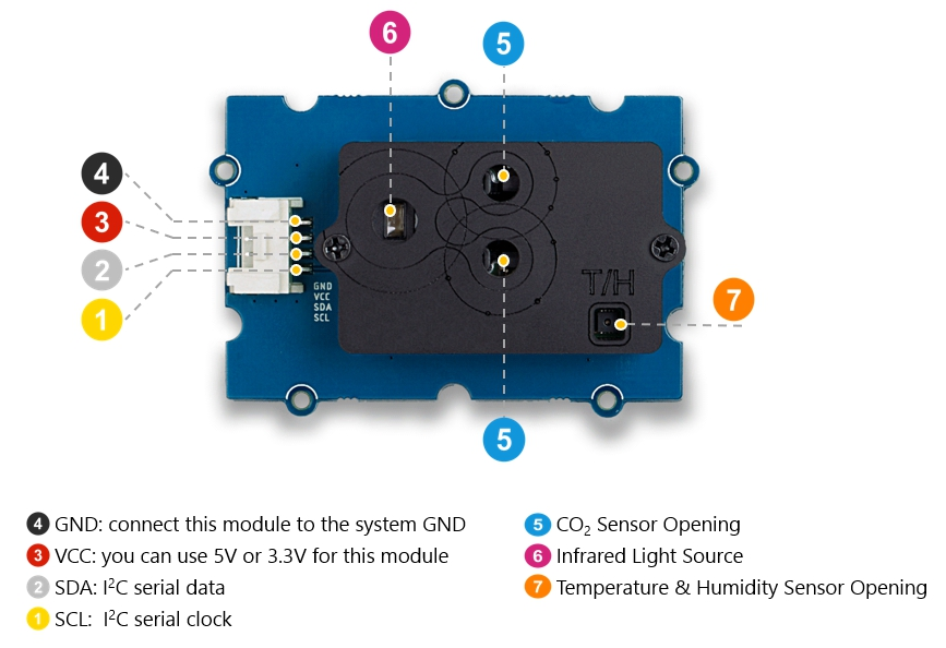

- Plage de détection : 0-40000 ppm
- Précision : entre 400-10000ppm± (30 ppm + 3 %)
- Calibrage : Lors de la première activation, une période d'au moins 7 jours est nécessaire pour que l'algorithme puisse trouver son jeu de paramètres initiaux pour l'ASC. Le capteur doit être exposé à l'air frais pendant au moins 1 heure chaque jour. Pendant cette période également, le capteur ne doit pas être débranché de l'alimentation électrique, sinon la procédure de recherche des paramètres d'étalonnage est interrompue et doit être recommencée depuis le début. Les paramètres calculés avec succès sont stockés dans la mémoire non volatile du SCD30, ce qui fait qu'après un réinitialisé, les paramètres trouvés précédemment pour l'ASC sont toujours présents.
Code SCD30
#include "SCD30.h"

#if defined(ARDUINO_ARCH_AVR)
 #pragma message("Defined architecture for ARDUINO_ARCH_AVR.")
 #define SERIAL Serial
#elif defined(ARDUINO_ARCH_SAM)
 #pragma message("Defined architecture for ARDUINO_ARCH_SAM.")
 #define SERIAL SerialUSB
#elif defined(ARDUINO_ARCH_SAMD)
 #pragma message("Defined architecture for ARDUINO_ARCH_SAMD.")
 #define SERIAL SerialUSB
#elif defined(ARDUINO_ARCH_STM32F4)
 #pragma message("Defined architecture for ARDUINO_ARCH_STM32F4.")
 #define SERIAL SerialUSB
#else
 #pragma message("Not found any architecture.")
 #define SERIAL Serial
#endif


void setup()
{
    Wire.begin();
    SERIAL.begin(115200);
    SERIAL.println("SCD30 Raw Data");
    scd30.initialize();
}

void loop()
{
    float result[3] = {0};

    if(scd30.isAvailable())
    {
        scd30.getCarbonDioxideConcentration(result);
        SERIAL.print("Carbon Dioxide Concentration is: ");
        SERIAL.print(result[0]);
        SERIAL.println(" ppm");
        SERIAL.println(" ");
        SERIAL.print("Temperature = ");
        SERIAL.print(result[1]);
        SERIAL.println(" ℃");
        SERIAL.println(" ");
        SERIAL.print("Humidity = ");
        SERIAL.print(result[2]);
        SERIAL.println(" %");
        SERIAL.println(" ");
        SERIAL.println(" ");
        SERIAL.println(" ");
    }

    delay(2000);
}
Grove Capteur de gaz CO2 MH-Z16 : https://wiki.seeedstudio.com/Grove-CO2_Sensor/
Le capteur MH-Z16 est un capteur de CO2 infrarouge non-dispersif(NDIR)
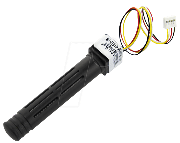
- Gaz cible : CO2
- Caractéristiques : grand champ de détection, stable et longue durée de vie, haute sensibilité
- Champs d'application : Surveillance de la CVC et de la qualité de l'air, de la sécurité des processus industriels et des processus de production agricole et animale
- Plage de détection : CO2 : 0-2000 ppm
- Plage de résolution : 1 ppm
- Précision : 200 ppm
- Température de fonctionnement : 0 à 50℃
- Humidité de fonctionnement : 0 % ~ 90 % HR
- Température de stockage : - 20-60 ℃
- Tension de fonctionnement : 4,5V à 6V
- Interface : UART
Code MH-Z16
/*
  This test code is write for Arduino AVR Series(UNO, Leonardo, Mega)
  If you want to use with LinkIt ONE, please connect the module to D0/1 and modify:

  // #include <SoftwareSerial.h>
  // SoftwareSerial s_serial(2, 3);      // TX, RX

  #define sensor Serial1
*/


#include <SoftwareSerial.h>
SoftwareSerial s_serial(2, 3);      // TX, RX

#define sensor s_serial

const unsigned char cmd_get_sensor[] =
{
    0xff, 0x01, 0x86, 0x00, 0x00,
    0x00, 0x00, 0x00, 0x79
};

unsigned char dataRevice[9];
int CO2PPM;

void setup()
{
    sensor.begin(9600);
    Serial.begin(9600);
    Serial.println("get a 'g', begin to read from sensor!");
    Serial.println("********************************************************");
    Serial.println();
}

void loop()
{
    if(dataRecieve())
    {
        Serial.print("  CO2: ");
        Serial.print(CO2PPM);
        Serial.println("");
    }
    delay(10000);
}

bool dataRecieve(void)
{
    byte data[9];
    int i = 0;

    //transmit command data
    for(i=0; i<sizeof(cmd_get_sensor); i++)
    {
        sensor.write(cmd_get_sensor[i]);
    }
    Serial.flush();

    //begin reveiceing data
    if(sensor.available())
    {
        while(sensor.available())
        {
            for(int i=0;i<9; i++)
            {
                data[i] = sensor.read();
            }
        }
    }

    for(int j=0; j<9; j++)
    {
        Serial.print(data[j],HEX);
        Serial.print(" ");
    }
    Serial.println("");

    // First calculate then validate the check sum as there is no point in proceeding if the packet is corrupted. (code inspired by datasheet algorithm)
    byte checksum = 0 ;
    for(int j=1; j<8; j++)
    {
      checksum += data[j];
    }
    checksum=0xff-checksum;
    checksum+=1;

    if  (checksum != data[8])
    {
      Serial.println("Error checksum");
      return false;
    }

    // Then check the start byte to make sure response is what we were expecting
    if ( data[0] != 0xFF )
    {
        Serial.println("Error start byte");
        return false;
    }

    // Then check the command byte to make sure response is what we were expecting
    if ( data[1] != 0x86 )
    {
        Serial.println("Error command");
        return false;
    }


    CO2PPM = (int)data[2] * 256 + (int)data[3];

    return true;
}
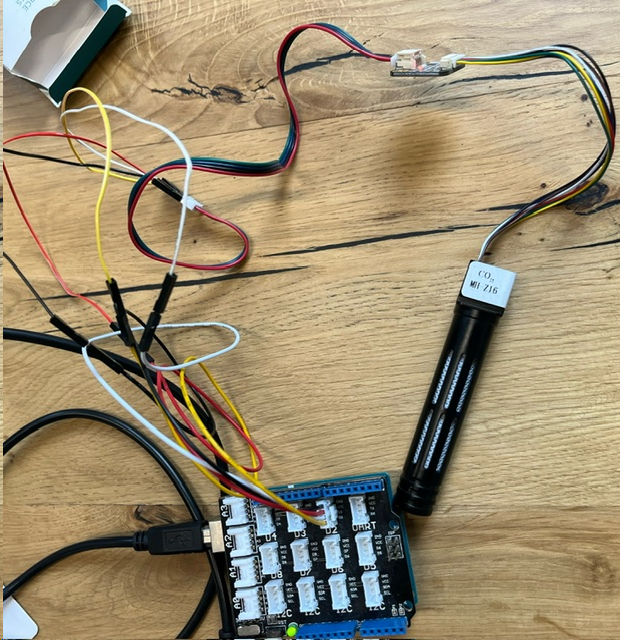
Le code ci-dessus fonctionne et affiche la valeur du CO2 présent dans la pièce. Cette valeur augmente lorsqu'on souffle sur le capteur.
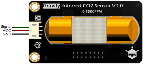
Capteur de CO2 infrarouge Grove Gravity V1.1 : https://circuitdigest.com/microcontroller-projects/interfacing-gravity-inrared-co2-sensor-to-measure-carbon-dioxyde-in-ppm
Code Gravity
int sensorIn = A4;
#include <SPI.h>
#include <Adafruit_GFX.h>
#include <Adafruit_SSD1306.h>
#define SCREEN_WIDTH 128 // OLED display width, in pixels
#define SCREEN_HEIGHT 64 // OLED display height, in pixels
// Declaration for SSD1306 display connected using software SPI (default case):
#define OLED_MOSI   9
#define OLED_CLK   10
#define OLED_DC    11
#define OLED_CS    12
#define OLED_RESET 13
Adafruit_SSD1306 display(SCREEN_WIDTH, SCREEN_HEIGHT,
  OLED_MOSI, OLED_CLK, OLED_DC, OLED_RESET, OLED_CS);
void setup(){
  Serial.begin(9600);
  // Set the default voltage of the reference voltage
  analogReference(DEFAULT);
  display.begin(SSD1306_SWITCHCAPVCC);
  display.clearDisplay();
  display.display();
}
void loop(){
  //Read voltage
  int sensorValue = analogRead(sensorIn);
  // The analog signal is converted to a voltage
  float voltage = sensorValue*(5000/1024.0);
  if(voltage == 0)
  {
    Serial.println("Fault");
  }
  else if(voltage < 400)
  {
    Serial.println("preheating");
  }
  else
  {
    int voltage_diference=voltage-400;
    float concentration=voltage_diference*50.0/16.0;
    // Print Voltage
    Serial.print("voltage: ");
    Serial.print(voltage);
    Serial.println("mv");
    //Print CO2 concentration
    Serial.print("CO2 Concentration: ");
    Serial.print(concentration);
    Serial.println("ppm");
    display.setTextSize(2);
    display.setTextColor(WHITE);
    display.setCursor(18,43);
    display.println("CO2");
    display.setCursor(63,43);
    display.println("(PPM)");
    display.setTextSize(2);
    display.setCursor(28,5);
    display.println(concentration);
    display.display();
    display.clearDisplay();
  }
  delay(2000);
}
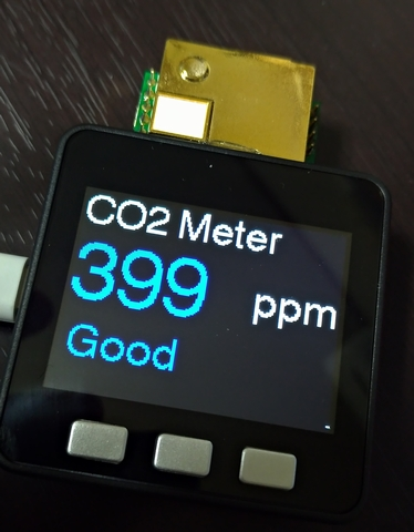
Capteur CO2 MHZ19B avec M5STACK : https://github.com/toripoyo/M5Stack_MH-Z19B_Digital/blob/master/README.md
Code MHZ-19B
#include <M5Stack.h>

const uint8_t kCommandLen = 9;
const uint8_t kResponseLen = 9;
const uint8_t kReadCommand[kCommandLen] = {0xFF, 0x01, 0x86, 0x00, 0x00, 0x00, 0x00, 0x00, 0x79};
const uint8_t kResetCommand[kCommandLen] = {0xFF, 0x01, 0x87, 0x00, 0x00, 0x00, 0x00, 0x00, 0x78};

// BackGround Picture Data
extern const unsigned short BGPicture[];

// Function Define
void drawPPMVal(uint16_t);
void drawBlueScreen(String);

void setup()
{
  M5.begin();
  Serial2.begin(9600);
  M5.Lcd.setTextColor(TFT_WHITE);
  M5.Lcd.setTextFont(4);

  // Calibration
  M5.update();
  if (M5.BtnB.isPressed())
  {
    Serial2.write(kResetCommand, kCommandLen);
    drawBlueScreen("Resetting...");
    delay(5000);
    M5.Power.reset();
  }
}

void loop()
{
  uint8_t response[kResponseLen] = {};

  // Read Current ppm
  Serial2.write(kReadCommand, kCommandLen);
  Serial2.readBytes(response, kResponseLen);

  // resnponse is ok
  if (response[0] == 0xFF && response[1] == 0x86)
  {
    uint16_t meas_PPM = (256 * response[2]) + response[3];
    drawPPMVal(meas_PPM);
    delay(1000);
  }
  else
  {
    drawBlueScreen("Invalid Response!");
    delay(3000);
    M5.Power.reset();
  }
}

// ---------------------------------------------------------------------

// Draw Blue Screen
void drawBlueScreen(String s)
{
  M5.Lcd.fillScreen(TFT_BLUE);
  M5.Lcd.setTextColor(TFT_WHITE);
  M5.Lcd.setTextSize(1);
  M5.Lcd.drawString(s, 0, 100);
}

// Draw Now Data
void drawPPMVal(uint16_t ppm)
{
  const uint16_t x_offset = 40;
  static uint16_t ppm_old = 0;

  if (ppm != ppm_old)
  {
    ppm_old = ppm;

    M5.Lcd.setTextColor(TFT_WHITE);
    M5.Lcd.setTextSize(1);
    M5.Lcd.drawString("CO2 Meter", 0, 0);
    M5.Lcd.setTextSize(2);
    M5.Lcd.drawString("ppm", 220, 160);

    if (ppm >= 1500)
    {
      M5.Lcd.setTextColor(TFT_RED);
      M5.Lcd.drawString("Warning!", 5, 160);
    }
    else if (ppm >= 1000 && ppm < 1500)
    {
      M5.Lcd.setTextColor(TFT_ORANGE);
    }
    else if (ppm >= 500 && ppm < 1000)
    {
      M5.Lcd.setTextColor(TFT_GREEN);
    }
    else if (ppm < 500)
    {
      M5.Lcd.setTextColor(TFT_BLUE);
    }
    M5.Lcd.fillRect(30, 50, 240, 100, TFT_BLACK);
    M5.Lcd.drawNumber(ppm, 40, 60, 6);
  }
}
Jour 3 & 4 : Création d'un data logger MQ2
Création d'un Data Logger :
https://docs.arduino.cc/tutorials/mkr-zero/mkr-zero-data-logger/
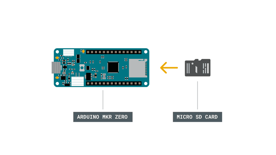
On commence par connecter la carte SD à la carte arduino MKRZero. On obtient 3 séries de chiffres pour les 3 sorties. On récupère ensuite la carte SD, les données se trouvent alors dans un fichier DATA.txt.
lien pour rectifier l'erreur "Compilation error no such file or directory" : https://www.programmingelectronics.com/no-such-file-error/#:~:text=If%20you%20don't%20see,%3E%20Include%20Library%20%3E%20Manage%20Libraries.
Code Data logger
/*!
 *  @file DHT.h
 *
 *  This is a library for DHT series of low cost temperature/humidity sensors.
 *
 *  You must have Adafruit Unified Sensor Library library installed to use this
 * class.
 *
 *  Adafruit invests time and resources providing this open source code,
 *  please support Adafruit andopen-source hardware by purchasing products
 *  from Adafruit!
 *
 *  Written by Adafruit Industries.
 *
 *  MIT license, all text above must be included in any redistribution
 */

#ifndef DHT_H
#define DHT_H

#include "Arduino.h"

/* Uncomment to enable printing out nice debug messages. */
//#define DHT_DEBUG

#define DEBUG_PRINTER                                                          \
  Serial /**< Define where debug output will be printed.                       \
          */

/* Setup debug printing macros. */
#ifdef DHT_DEBUG
#define DEBUG_PRINT(...)                                                       \
  { DEBUG_PRINTER.print(__VA_ARGS__); }
#define DEBUG_PRINTLN(...)                                                     \
  { DEBUG_PRINTER.println(__VA_ARGS__); }
#else
#define DEBUG_PRINT(...)                                                       \
  {} /**< Debug Print Placeholder if Debug is disabled */
#define DEBUG_PRINTLN(...)                                                     \
  {} /**< Debug Print Line Placeholder if Debug is disabled */
#endif

/* Define types of sensors. */
static const uint8_t DHT11{11};  /**< DHT TYPE 11 */
static const uint8_t DHT12{12};  /**< DHY TYPE 12 */
static const uint8_t DHT21{21};  /**< DHT TYPE 21 */
static const uint8_t DHT22{22};  /**< DHT TYPE 22 */
static const uint8_t AM2301{21}; /**< AM2301 */

#if defined(TARGET_NAME) && (TARGET_NAME == ARDUINO_NANO33BLE)
#ifndef microsecondsToClockCycles
/*!
 * As of 7 Sep 2020 the Arduino Nano 33 BLE boards do not have
 * microsecondsToClockCycles defined.
 */
#define microsecondsToClockCycles(a) ((a) * (SystemCoreClock / 1000000L))
#endif
#endif

/*!
 *  @brief  Class that stores state and functions for DHT
 */
class DHT {
public:
  DHT(uint8_t pin, uint8_t type, uint8_t count = 6);
  void begin(uint8_t usec = 55);
  float readTemperature(bool S = false, bool force = false);
  float convertCtoF(float);
  float convertFtoC(float);
  float computeHeatIndex(bool isFahrenheit = true);
  float computeHeatIndex(float temperature, float percentHumidity,
                         bool isFahrenheit = true);
  float readHumidity(bool force = false);
  bool read(bool force = false);

private:
  uint8_t data[5];
  uint8_t _pin, _type;
#ifdef __AVR
  // Use direct GPIO access on an 8-bit AVR so keep track of the port and
  // bitmask for the digital pin connected to the DHT.  Other platforms will use
  // digitalRead.
  uint8_t _bit, _port;
#endif
  uint32_t _lastreadtime, _maxcycles;
  bool _lastresult;
  uint8_t pullTime; // Time (in usec) to pull up data line before reading

  uint32_t expectPulse(bool level);
};

/*!
 *  @brief  Class that defines Interrupt Lock Avaiability
 */
class InterruptLock {
public:
  InterruptLock() {
#if !defined(ARDUINO_ARCH_NRF52)
    noInterrupts();
#endif
  }
  ~InterruptLock() {
#if !defined(ARDUINO_ARCH_NRF52)
    interrupts();
#endif
  }
};

#endif
2 ème Code Data Logger
#include <SPI.h>
#include <SD.h>

const int chipSelect = SDCARD_SS_PIN;

void setup() {
  // Open serial communications and wait for port to open:
  Serial.begin(9600);
  while (!Serial) {
    ; // wait for serial port to connect. Needed for native USB port only
  }


  Serial.print("Initializing SD card...");

  // see if the card is present and can be initialized:
  if (!SD.begin(chipSelect)) {
    Serial.println("Card failed, or not present");
    // don't do anything more:
    while (1);
  }
  Serial.println("card initialized.");
}

void loop() {
  // make a string for assembling the data to log:
  String dataString = "";

  // read three sensors and append to the string:
  for (int analogPin = 0; analogPin < 3; analogPin++) {
    int sensor = analogRead(analogPin);
    dataString += String(sensor);
    if (analogPin < 2) {
      dataString += ",";
    }
  }

  // open the file. note that only one file can be open at a time,
  // so you have to close this one before opening another.
  File dataFile = SD.open("datalog.txt", FILE_WRITE);

  // if the file is available, write to it:
  if (dataFile) {
    dataFile.println(dataString);
    dataFile.close();
    // print to the serial port too:
    Serial.println(dataString);
  }
  // if the file isn't open, pop up an error:
  else {
    Serial.println("error opening datalog.txt");
  }
  delay(1000);
}
On ajoute un capteur de CO2 MQ2 :
lien youtube du montage et code : youtube.com/watch?v=8DQQDpaZYj8
Lien du github associé : https://github.com/harshkzz/Arduino-with-MQ2-Sensor-and-Serial-Monitor/blob/main/MQ-2-sensor-library-master.zip
2 codes qui donnent les mêmes résultats :
Code Data logger + capteur MQ2
#include<MQ2.h>

#define PIN A0

MQ2 mq2(PIN);

void setup() {
  Serial.begin(9600);
  mq2.begin();

}

void loop() {
  int lpg = mq2.readLPG();
  int co = mq2.readCO();
  int smo = mq2.readSmoke();
  Serial.print("Smoke: ");
  Serial.print(smo);
  Serial.print("  LPG: ");
  Serial.print(lpg);
  Serial.print("  CO2: ");
  Serial.println(co);
  delay(2000);
}
2ème code data logger + capteur MQ2
/*
Scheduled Datalogger
Demonstrates how to log temperature and humidity sensor
reading and time using a MKRZero, then you can plot the
graph of the temperature and humidity in a romm during
the whole day!
This example code is in the public domain
Parts required:
1 DHT22 temperature and humidity sensor
1 MKR protoshield
created by Arturo Guadalupi <a.guadalupi@arduino.cc>
3 Nov 2016
*/
#include <SD.h>
#include <RTCZero.h>
#include <DHT.h>
#define DHTPIN 7
#define DHTTYPE DHT22
DHT dht(DHTPIN, DHTTYPE);
const int chipSelect = SS1;
unsigned long previousTime;
int loadDataCheck; //Checks if data needs to be loaded
RTCZero rtc;
/* Change these values to set the current initial time */
const byte seconds = 50;
const byte minutes = 44;
const byte hours = 17;
/* Change these values to set the current initial date */
const byte day = 1;
const byte month = 9;
const byte year = 16;
// the setup function runs once when you press reset
// or power the board
void setup() {
// initialize digital pin LED_BUILTIN as an output.
pinMode(LED_BUILTIN, OUTPUT);
Serial.begin(9600);
Serial.println("DataLogger Example:");
// see if the card is present and can be initialized:
if (!SD.begin(chipSelect)) {
Serial.println("Card failed, or not present");
// don't do anything more:
return;
}
Serial.println("card initialized.");
//When power is supplied to the DHT22 sensor,
//don't send any instruction to the sensor
//within one second to pass unstable status
delay(1000);
Serial.println("Initializing DHT");
dht.begin();
Serial.println("Initializing RTC");
rtc.begin();
rtc.setTime(hours, minutes, seconds);
rtc.setDate(day, month, year);
rtc.setAlarmTime(0, 0, 0);
rtc.enableAlarm(rtc.MATCH_SS); //alarm attached every minute
rtc.attachInterrupt(dataCheck);
loadDataCheck=0;
previousTime=millis();
Serial.println("System ready...");
}
// the loop function runs over and over again forever
void loop() {
unsigned long currentTime=millis();
if ((currentTime-previousTime)>5000)
{
digitalWrite(LED_BUILTIN, HIGH); // turn the LED on
delay(100); // wait for a bit
digitalWrite(LED_BUILTIN, LOW); // turn the LED off
previousTime=millis();
}
if (loadDataCheck) logData();
}
void dataCheck(){
loadDataCheck=1;
}
void logData(void) {
float humidity = dht.readHumidity();
float temperature = dht.readTemperature();
String dataString = "";
dataString += "Temperature: " + String(temperature) + " C" + "\t" + "Humidity: " + String(humidity) + "%\t" + "Time: " + getTime();
// open the file. note that only one file can be open at a time,
// so you have to close this one before opening another.
File dataFile = SD.open("datalog.txt", FILE_WRITE);
// if the file is available, write to it:
if (dataFile) {
dataFile.println(dataString);
dataFile.close();
// print to the Serial port too:
Serial.println(dataString);
}
// if the file isn't open, pop up an error:
else {
Serial.println("error opening datalog.txt");
}
loadDataCheck=0;
}
String getTime(void) {
String returnString = "";
if (rtc.getHours() < 10)
returnString += "0" + String(rtc.getHours());
else
returnString += String(rtc.getHours());
returnString += ":";
if (rtc.getMinutes() < 10)
returnString += "0" + String(rtc.getMinutes());
else
returnString += String(rtc.getMinutes());
returnString += ":";
if (rtc.getSeconds() < 10)
returnString += "0" + String(rtc.getSeconds());
else
returnString += String(rtc.getSeconds());
return returnString;
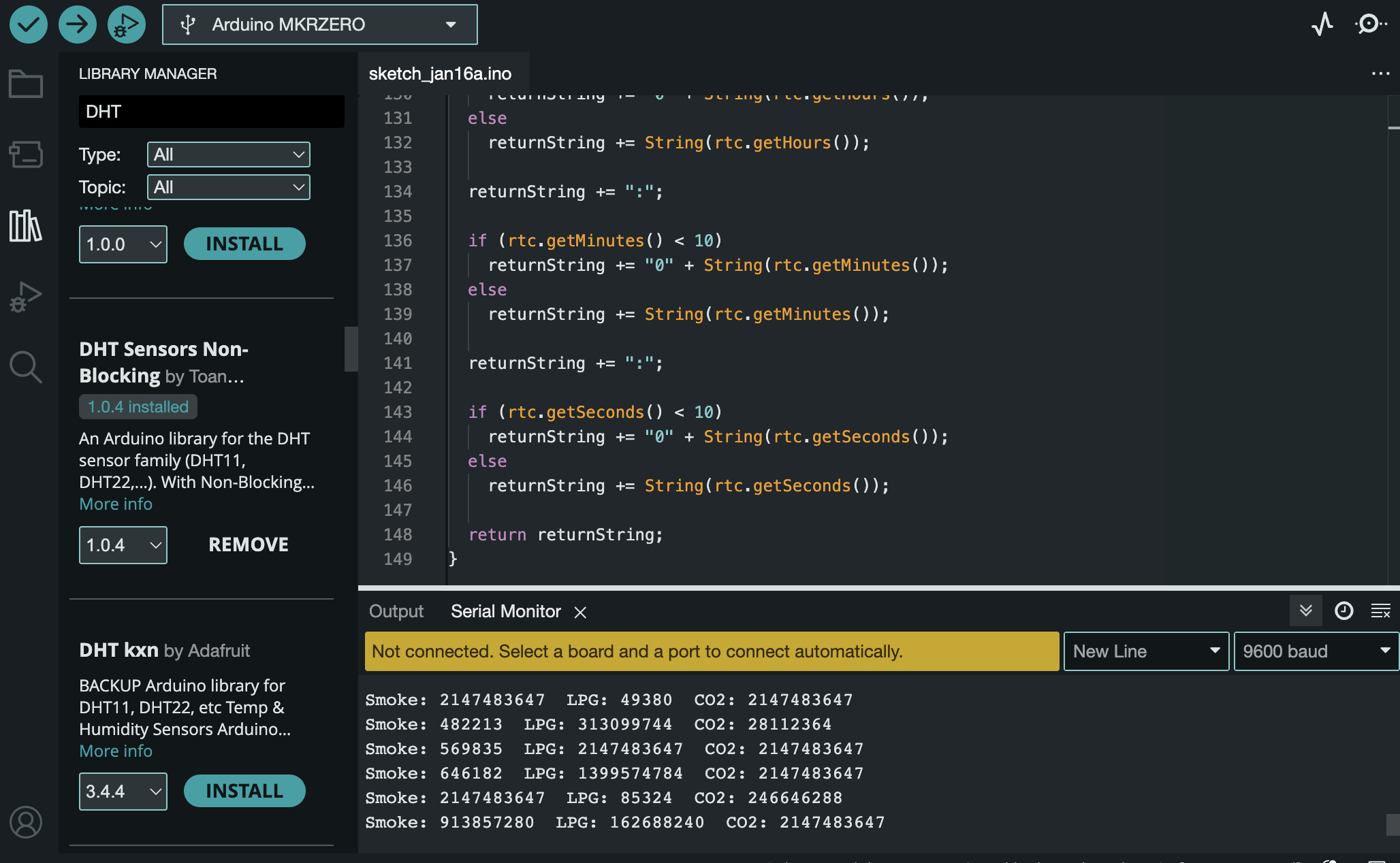
}On obtient les valeurs de fumée, LPG et CO2. Je pense qu'il faut calibrer le capteur, il n'y a pas d'unités.
Ensuite j'ai essayé d'enregistrer les valeurs du capteur sur la carte SD :
On utilise le code suivant qui est un mix des codes précédents :
Code pour enregistrer les valeurs du capteur sur la carte SD
#include <SPI.h>
#include <SD.h>
#include<MQ2.h>

const int chipSelect = SDCARD_SS_PIN;
#define PIN A0
MQ2 mq2(PIN);

void setup() {
  // Open serial communications and wait for port to open:
  Serial.begin(9600);
  while (!Serial)
   {
    ; // wait for serial port to connect. Needed for native USB port only
  }


  Serial.print("Initializing SD card...");

  // see if the card is present and can be initialized:
  if (!SD.begin(chipSelect)) {
    Serial.println("Card failed, or not present");
    // don't do anything more:
    while (1);
  }
  Serial.println("card initialized.");
}


void loop() {
  // make a string for assembling the data to log:
  String dataString = "";

  // read three sensors and append to the string:
  int lpg = mq2.readLPG();
  int co = mq2.readCO();
  int smo = mq2.readSmoke();
  Serial.print("Smoke: ");
  Serial.print(smo);
  Serial.print("  LPG: ");
  Serial.print(lpg);
  Serial.print("  CO2: ");
  Serial.println(co);
  delay(2000);
  dataString += String(lpg);
  dataString += ",";
  dataString += String(co);
  dataString += ",";
  dataString += String(smo);
  dataString += ",";

  // open the file. note that only one file can be open at a time,
  // so you have to close this one before opening another.
  File dataFile = SD.open("datalog.txt", FILE_WRITE);

  // if the file is available, write to it:
  if (dataFile) {
    dataFile.println(dataString);
    dataFile.close();
    // print to the serial port too:
    Serial.println(dataString);
  }
  // if the file isn't open, pop up an error:
  else {
    Serial.println("error opening datalog.txt");
  }
  delay(1000);
}
Les valeurs s'enregistrent bien à la suite des valeurs aléatoires sur le fichier DATALOG.TXT, j'ai crée un dossier DATALOGCO2 - copie qui ne contient que les valeurs récupérées des capteurs.
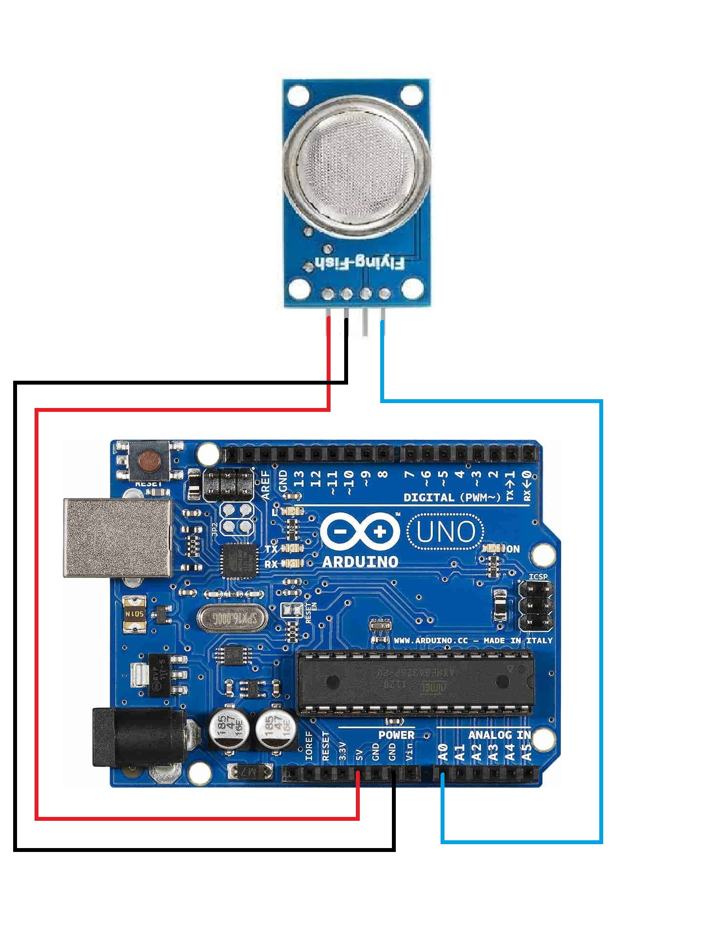
On essaye maintenant de connecter plusieurs capteurs. On connecte deux capteurs MQ2 à une arduino uno. On utilise le code suivant, on récupère las valeurs des deux capteurs.
Code pour connecter plusieurs capteurs Arduino Uno
void setup() {
    Serial.begin(9600);
}

void loop() {
    float sensor_volt;
    float sensorValue;
    float sensor_volt2;
    float sensorValue2;

    sensorValue = analogRead(A0);
    sensor_volt = sensorValue/1024*5.0;
    sensorValue2 = analogRead(A1);
    sensor_volt2 = sensorValue2/10224*5.0;

    Serial.print("sensor_volt = ");
    Serial.print(sensor_volt);
    Serial.println("V");
    Serial.print("sensor_volt2 = ");
    Serial.print(sensor_volt2);
    Serial.println("V");
    delay(1000);
}
On connecte maintenant les deux capteurs MQ2 à une arduino MKRZero avec le code suivant, on obtient les mêmes valeurs sur les deux lignes, une ligne en plus avec des valeurs qui correspondent peut être au second capteur et une ligne de 0 qui ne correspond à rien. Le fichier sur la carte SD lui ne comporte pas deux lignes avec les mêmes valeurs.
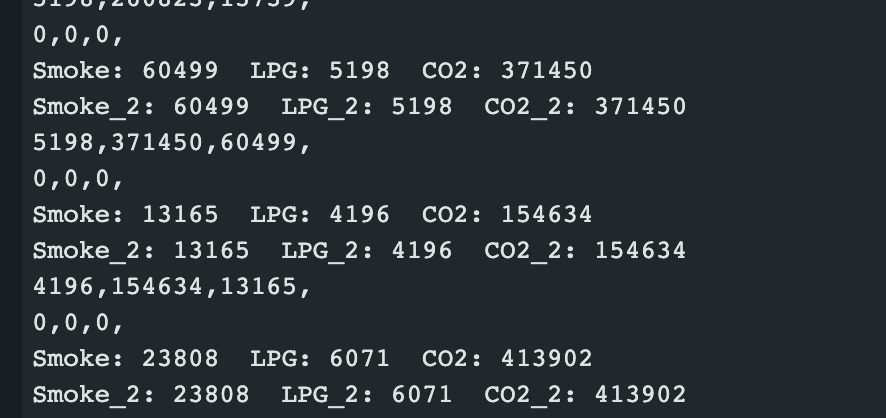
Code pour connecter deux capteurs à une MKRZero
#include <SPI.h>
#include <SD.h>
#include<MQ2.h>

int chipSelect = SDCARD_SS_PIN;
#define PIN A0
#define PIN2 A1
MQ2 mq2(PIN);
MQ2 mq22(PIN2);

void setup() {
  // Open serial communications and wait for port to open:
  Serial.begin(9600);
  while (!Serial)
   {
    ; // wait for serial port to connect. Needed for native USB port only
  }


  Serial.print("Initializing SD card...");

  // see if the card is present and can be initialized:
  if (!SD.begin(chipSelect)) {
    Serial.println("Card failed, or not present");
    // don't do anything more:
    while (1);
  }
  Serial.println("card initialized.");
}


void loop() {
  // make a string for assembling the data to log:
  String dataString = "";
  String dataString2 = "";

  // read three sensors and append to the string:
  int lpg = mq2.readLPG();
  int co = mq2.readCO();
  int smo = mq2.readSmoke();
  Serial.print("Smoke: ");
  Serial.print(smo);
  Serial.print("  LPG: ");
  Serial.print(lpg);
  Serial.print("  CO2: ");
  Serial.println(co);
  delay(2000);
  dataString += String(lpg);
  dataString += ",";
  dataString += String(co);
  dataString += ",";
  dataString += String(smo);
  dataString += ",";
  int lpg2 = mq22.readLPG();
  int co2 = mq22.readCO();
  int smo2 = mq22.readSmoke();
  Serial.print("Smoke_2: ");
  Serial.print(smo);
  Serial.print("  LPG_2: ");
  Serial.print(lpg);
  Serial.print("  CO2_2: ");
  Serial.println(co);
  delay(2000);
  dataString2 += String(lpg2);
  dataString2 += ",";
  dataString2 += String(co2);
  dataString2 += ",";
  dataString2 += String(smo2);
  dataString2 += ",";


  // open the file. note that only one file can be open at a time,
  // so you have to close this one before opening another.
  File dataFile = SD.open("datalog.txt", FILE_WRITE);

  // if the file is available, write to it:
  if (dataFile) {
    dataFile.println(dataString);
    dataFile.close();
    // print to the serial port too:
    Serial.println(dataString);
    Serial.println(dataString2);
  }
  // if the file isn't open, pop up an error:
  else {
    Serial.println("error opening datalog.txt");
  }
  delay(1000);
}
Code pour créer une horloge RTC, on obtient la date et l'heure : https://docs.arduino.cc/tutorials/generic/simple-rtc/
Code pour créer une horloge
/*
Simple RTC for Arduino Zero and MKR1000
Demonstrates the use of the RTC library for the Arduino Zero and MKR1000
This example code is in the public domain
https://www.arduino.cc/en/Tutorial/SimpleRTC
created by Arturo Guadalupi <a.guadalupi@arduino.cc>
15 Jun 2015
modified
18 Feb 2016
modified by Andrea Richetta <a.richetta@arduino.cc>
24 Aug 2016
*/
#include <RTCZero.h>
/* Create an rtc object */
RTCZero rtc;
/* Change these values to set the current initial time */
const byte seconds = 0;
const byte minutes = 0;
const byte hours = 16;
/* Change these values to set the current initial date */
const byte day = 15;
const byte month = 6;
const byte year = 15;
void setup()
{
Serial.begin(9600);
rtc.begin(); // initialize RTC
// Set the time
rtc.setHours(hours);
rtc.setMinutes(minutes);
rtc.setSeconds(seconds);
// Set the date
rtc.setDay(day);
rtc.setMonth(month);
rtc.setYear(year);
// you can use also
//rtc.setTime(hours, minutes, seconds);
//rtc.setDate(day, month, year);
}
void loop()
{
// Print date...
print2digits(rtc.getDay());
Serial.print("/");
print2digits(rtc.getMonth());
Serial.print("/");
print2digits(rtc.getYear());
Serial.print(" ");
// ...and time
print2digits(rtc.getHours());
Serial.print(":");
print2digits(rtc.getMinutes());
Serial.print(":");
print2digits(rtc.getSeconds());
Serial.println();
delay(1000);
}
void print2digits(int number) {
if (number < 10) {
Serial.print("0"); // print a 0 before if the number is < than 10
}
Serial.print(number);
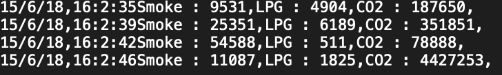
}On essaye maintenant de rajouter une horloge au data logger avec le code suivant :
On obtient sur la carte SD la date, l'heure et les valeurs du capteur :
Code pour ajouter l'horloge au Data logger
#include <SPI.h>
#include <SD.h>
#include<MQ2.h>
#include <RTCZero.h>

const int chipSelect = SDCARD_SS_PIN;
#define PIN A0
MQ2 mq2(PIN);

/* Create an rtc object */
RTCZero rtc;
const byte seconds = 0;
const byte minutes = 0;
const byte hours = 16;
const byte day = 15;
const byte month = 6;
const byte year = 18;


void setup() {
  // Open serial communications and wait for port to open:
  Serial.begin(9600);
  while (!Serial)
   {
    ; // wait for serial port to connect. Needed for native USB port only
  }


  Serial.print("Initializing SD card...");

  // see if the card is present and can be initialized:
  if (!SD.begin(chipSelect)) {
    Serial.println("Card failed, or not present");
    // don't do anything more:
    while (1);
  }
  Serial.println("card initialized.");

  rtc.begin(); // initialize RTC

  rtc.setHours(hours);
  rtc.setMinutes(minutes);
  rtc.setSeconds(seconds);
  rtc.setDay(day);
  rtc.setMonth(month);
  rtc.setYear(year);


}


void loop() {

  Serial.print(rtc.getDay());
  Serial.print("/");
  Serial.print(rtc.getMonth());
  Serial.print("/");
  Serial.print(rtc.getYear());
  Serial.print(" ");
  Serial.print(rtc.getHours());
  Serial.print(":");
  Serial.print(rtc.getMinutes());
  Serial.print(":");
  Serial.print(rtc.getSeconds());
  Serial.println();
  // make a string for assembling the data to log:
  String dataString = "";

  // read three sensors and append to the string:
  int lpg = mq2.readLPG();
  int co = mq2.readCO();
  int smo = mq2.readSmoke();
  Serial.print("Smoke: ");
  Serial.print(smo);
  Serial.print("  LPG: ");
  Serial.print(lpg);
  Serial.print("  CO2: ");
  Serial.println(co);
  delay(2000);

  dataString += String(rtc.getDay());
  dataString +="/";
  dataString += String(rtc.getMonth());
  dataString +="/";
  dataString += String(rtc.getYear());
  dataString +=",";
  dataString += String(rtc.getHours());
  dataString +=":";
  dataString += String(rtc.getMinutes());
  dataString +=":";
  dataString += String(rtc.getSeconds());

  dataString += "Smoke : ";
  dataString += String(smo);
  dataString += ",";
  dataString += "LPG : ";
  dataString += String(lpg);
  dataString += ",";
  dataString += "CO2 : ";
  dataString += String(co);
  dataString += ",";

  // open the file. note that only one file can be open at a time,
  // so you have to close this one before opening another.
  File dataFile = SD.open("datalog.txt", FILE_WRITE);

  // if the file is available, write to it:
  if (dataFile) {
    dataFile.println(dataString);
    dataFile.close();
    // print to the serial port too:
    Serial.println(dataString);
  }
  // if the file isn't open, pop up an error:
  else {
    Serial.println("error opening datalog.txt");
  }
  delay(1000);
}
Exemple de code qui obtient la concentration en ppm grâce au capteur MQ2 en faisant la conversion : https://phmarduino.wordpress.com/2017/09/03/station-de-mesure-les-capteurs-2/
Jour 5 : Création de data logger avec différents capteurs
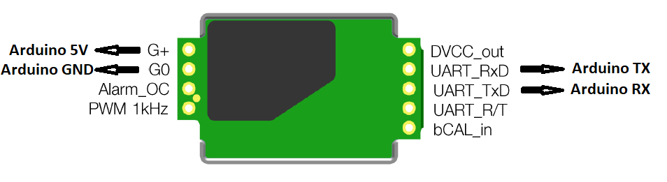
Capteur Sense Air S8 :
https://forum.arduino.cc/t/capteur-de-co2-senseair-s8-code-ultrasimple/1007731
Code Data logger capteur Sense Air S8
const byte CO2Command[] = {0xFE, 0X04, 0X00, 0X03, 0X00, 0X01, 0XD5, 0XC5};
byte Response[] = {0, 0, 0, 0, 0, 0, 0};
unsigned long val;

void setup() {
  Serial1.begin(9600);//Brancher le S8 sur RX1 et TX1
  Serial.begin(9600);
  delay(100);
  Serial.print("start");
}

void loop() {
  Serial1.write(CO2Command, 8);
  Serial1.readBytes(Response, 7);
  while (Serial1.available()) Serial1.read();//vidage du buffer
  if (Response[0] == 254) {
    val = Response[3] * 256 + Response[4];
    Serial.println(val);
  }
  else Serial.println("erreur CO2");
  delay(2000);
}
On obtient des valeurs. Lorsqu'on souffle sur le capteur les valeurs augmentent, on arrive à une saturation à 10000. Le capteur redescends vers 600/700 au repos.
Remarques (que vous pourrez effacer):
- vous pourriez ajouter une photo (des capteurs sur la table par exemple ou autre, qui pourra être changée à la fin du stage) sur la page d'entrée du wiki
- vous pourriez rédiger quelques lignes (~lignes) sur le contexte, les gaz à effet de serre, l'origine du CO2, du CH4 dans les sols, des ordres de grandeurs
- pour les capteurs, deux mots sur le principe de fonctionnement avec des liens (wikipédia est acceptable):
- capteurs à base de semiconducteur, transfert d'électrons et donc résistance électrique variable en fonction de la concentration en gaz. Dans les fiches techniques, vous avez la courbe de variation de la résistance du capteur en fonction de la concentration en gaz
- capteurs optiques NDIR qui mesurent l'absorption optique dans l'IR. Spécifique d'une molécule donnée donc moins d'interférences avec d'autres gaz
- précisez si vous avez réussi à lire les données du capteurs, ça ne m'a pas sera clair et en pratique ce n'est pas si évident (le dire et expliquez en quelques phrases comment vous avez réussi à faire)
- quelques liens en vrac que j'ai trouvé
#include <SPI.h>
#include <SD.h>
#include <Wire.h>


#include "SCD30.h"
float result[3] = {0}; // sensor readings


const int chipSelect = SDCARD_SS_PIN;

void setup() {
  Wire.begin();
  Serial.println("SCD30 Raw Data");
  scd30.initialize();
  // Open serial communications and wait for port to open:
  Serial.begin(9600);
  while (!Serial) {
    ; // wait for serial port to connect. Needed for native USB port only
  }


  Serial.print("Initializing SD card...");

  // see if the card is present and can be initialized:
  if (!SD.begin(chipSelect)) {
    Serial.println("Card failed, or not present");
    // don't do anything more:
    while (1);
  }
  Serial.println("card initialized.");
}

void loop() {
  if (scd30.isAvailable()) {
    scd30.getCarbonDioxideConcentration(result);
    Serial.print("Carbon Dioxide Concentration is: ");
    Serial.print(result[0]);
    Serial.println(" ppm");
  }

  // make a string for assembling the data to log:
  String dataString = "";

  // read three sensors and append to the string:
  for (int analogPin = 0; analogPin < 3; analogPin++) {
    float sensor = result[analogPin];
    dataString += String(sensor);
    if (analogPin < 2) {
      dataString += ",";
    }
  }

  // open the file. note that only one file can be open at a time,
  // so you have to close this one before opening another.
  File dataFile = SD.open("datalog.txt", FILE_WRITE);

  // if the file is available, write to it:
  if (dataFile) {
    dataFile.println(dataString);
    dataFile.close();
    // print to the serial port too:
    Serial.println(dataString);
  }
  // if the file isn't open, pop up an error:
  else {
    Serial.println("error opening datalog.txt");
  }
  delay(1000);
}
<code pour le capteur SenseAir S8
#include <SoftwareSerial.h>
// Define the RX and TX pins to establish UART communication
#define Pin_RX 4 // to RX
#define Pin_TX 5 // to TX
// Define the Serial sensor
SoftwareSerial sensor(Pin_RX, Pin_TX);
void setup() {
// Initiate the serial monitor.
Serial.begin(9600);
sensor.begin(9600);
}
void loop()
{
byte message[7] = {0xFE, 0x44, 0x00, 0x08, 0x02, 0x9F, 0x25};
sensor.write(message, 7);
delay(1000);
char buf[] = {' ',' ',' ',' ',' ',' ',' '}; // Receive up to 7 bytes
while (!sensor.available()); // Wait for characters
sensor.readBytes(buf, 7);
int measure;
byte b1 = buf[3];
byte b2 = buf[4];
measure = ((int)b1) * 256 + b2;
Serial.println(measure);
}
pour le capteur de CO2 jaune
https://github.com/nara256/mhz19_uart?tab=readme-ov-file
int sensorIn = A4;
#include <SPI.h>
#include <Adafruit_GFX.h>
#include <Adafruit_SSD1306.h>
#define SCREEN_WIDTH 128 // OLED display width, in pixels
#define SCREEN_HEIGHT 64 // OLED display height, in pixels
// Declaration for SSD1306 display connected using software SPI (default case):
#define OLED_MOSI   9
#define OLED_CLK   10
#define OLED_DC    11
#define OLED_CS    12
#define OLED_RESET 13
Adafruit_SSD1306 display(SCREEN_WIDTH, SCREEN_HEIGHT,
  OLED_MOSI, OLED_CLK, OLED_DC, OLED_RESET, OLED_CS);
void setup(){
  Serial.begin(9600);
  // Set the default voltage of the reference voltage
  analogReference(DEFAULT);
  display.begin(SSD1306_SWITCHCAPVCC);
  display.clearDisplay();
  display.display();
}
void loop(){
  //Read voltage
  int sensorValue = analogRead(sensorIn);
  // The analog signal is converted to a voltage
  float voltage = sensorValue*(5000/1024.0);
  if(voltage == 0)
  {
    Serial.println("Fault");
  }
  else if(voltage < 400)
  {
    Serial.println("preheating");
  }
  else
  {
    int voltage_diference=voltage-400;
    float concentration=voltage_diference*50.0/16.0;
    // Print Voltage
    Serial.print("voltage: ");
    Serial.print(voltage);
    Serial.println("mv");
    //Print CO2 concentration
    Serial.print("CO2 Concentration: ");
    Serial.print(concentration);
    Serial.println("ppm");
    display.setTextSize(2);
    display.setTextColor(WHITE);
    display.setCursor(18,43);
    display.println("CO2");
    display.setCursor(63,43);
    display.println("(PPM)");
    display.setTextSize(2);
    display.setCursor(28,5);
    display.println(concentration);
    display.display();
    display.clearDisplay();
  }
  delay(2000);
}